

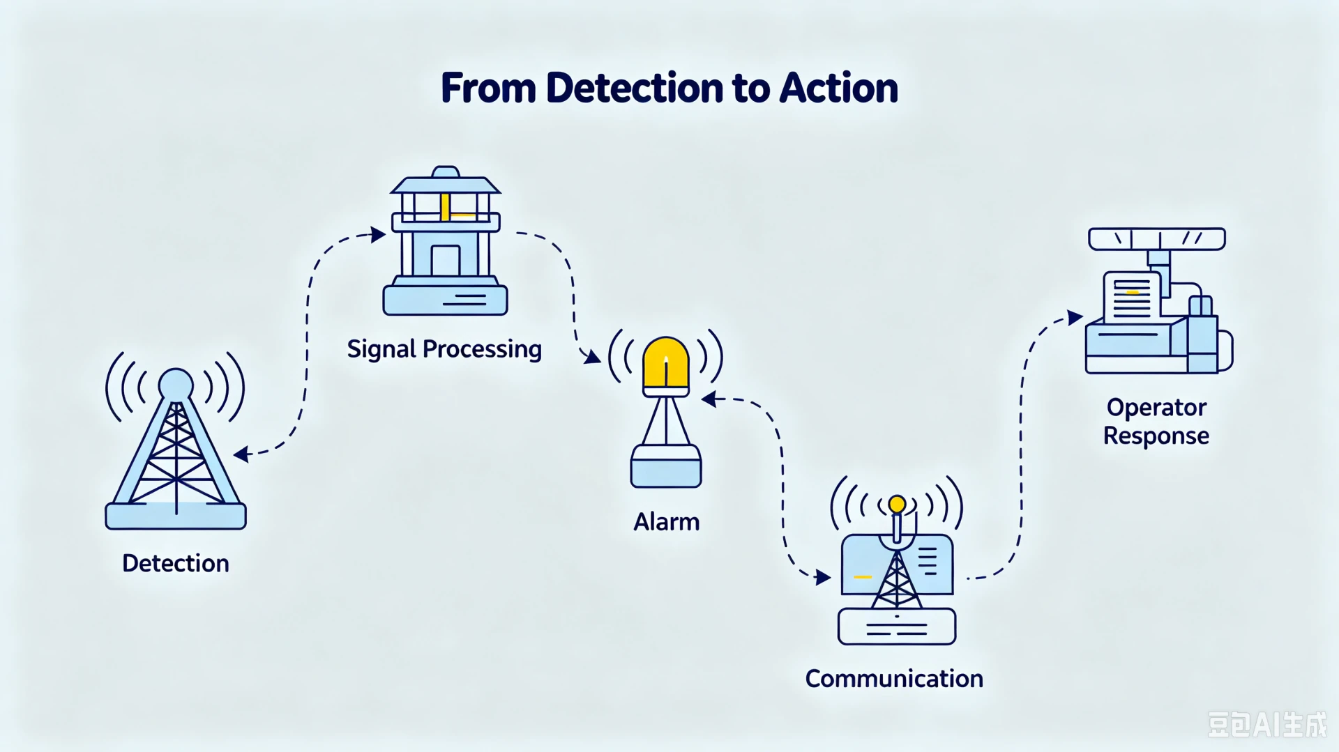
A transformer anti theft monitoring system detects abnormal physical and electrical conditions at a transformer site, triggers a local alarm, and reports the event to a remote operator within seconds. As of 2026 it is the standard electronic layer for protecting distribution transformers that sit far from staffed substations. A transformer in a remote area may see an inspection crew once a month; a theft takes minutes. This guide explains how the system is built and how the monitoring chain runs from sensor to operator. It also covers which communication option fits which site and, just as important, what such a system cannot do.
By Leon Zhang · Application Engineer, Baoding Houfeng Trading Co., Ltd. · Last updated: 4 October 2026
Key Takeaways
- A monitoring system is a chain, not a box: sensors, controller, local alarm and communication, platform, operator.
- It detects conditions such as vibration, tilt, cable cutting, power loss and enclosure entry. It does not detect thieves. A person still verifies every event.
- Event combination logic (for example, power loss plus vibration plus tilt) is what separates a useful system from a false-alarm generator.
- GSM, 4G Cat. 1 and NB-IoT all ride existing cellular networks. Coverage must be tested at the transformer itself, never assumed from a map.
- For unmanned rural sites the payback case is strong; for fenced substations with CCTV and patrols, it often is not.
What Is a Transformer Anti-Theft Monitoring System?
A transformer anti-theft monitoring system is a combination of sensors, a controller, a communication module and alarm outputs that watches selected physical and electrical conditions around a transformer and reports abnormal events to a remote operator. It is not a camera system or a fence, and it is certainly not a person. The job is narrower: to shrink the time between an abnormal event and a human decision.
That narrow definition matters because the system provides information, not judgment. It can tell you that a tank vibrated at 02:14 and the medium-voltage side lost two phases ninety seconds later. It cannot tell you whether that was a theft crew or a storm. The value comes from speed. An operator who receives a verified alarm in seconds can dispatch a patrol that still arrives in time instead of discovering copper theft at the next monthly inspection.
These systems are used wherever transformers sit unattended. The list includes rural distribution feeders, irrigation and agricultural installations, pole-mounted units on long lines, mining and oilfield sites, construction sites, and small remote substations. What the scenarios share is a low probability that anyone honest will be nearby when something happens. For a fuller picture of why distribution transformers attract thieves in the first place, see why distribution transformers are targeted.
One positioning note for planners: monitoring is one layer of prevention, not the whole answer. Measures that make a theft physically harder are covered separately in prevention measures that stop a theft before it starts. They include anti-theft bolts and locked enclosures; fencing and visible deterrence belong to the same layer. The two work together; neither substitutes for the other.
What Are the Main Components of a Transformer Anti Theft System?
Every transformer anti theft system in this equipment class, whatever the vendor calls it, is assembled from the same functional blocks: five sensing functions, one decision point, two output paths and a power reserve. The table below lists each block, its contribution and its typical pairing.
| Component | Function | Typically paired with |
|---|---|---|
| Vibration sensor | Detects tank or enclosure vibration from cutting, prying or movement | Pole-mounted and pad-mounted units |
| Tilt and movement sensor | Detects lifting, dragging or toppling of the transformer | Rural ground-mounted units |
| Cable monitoring module | Detects interruption or loss of connection on monitored cables | Overhead line entries |
| Power monitoring module | Detects loss of supply, phase loss or abnormal voltage | Nearly every site |
| Tamper sensor | Detects enclosure or terminal-box opening | All sites with a cabinet |
| Controller | Evaluates signals against thresholds and event logic | Always present |
| Local alarm | Siren and strobe that create noise and light at the site | Deterrence-first sites |
| Communication module | Carries events by SMS, cloud platform or SCADA | Always present |
| Backup battery | Keeps controller and communication alive when supply is cut | Always present |
The signal chain through these blocks is fixed, and every link must work for a report to reach a person.
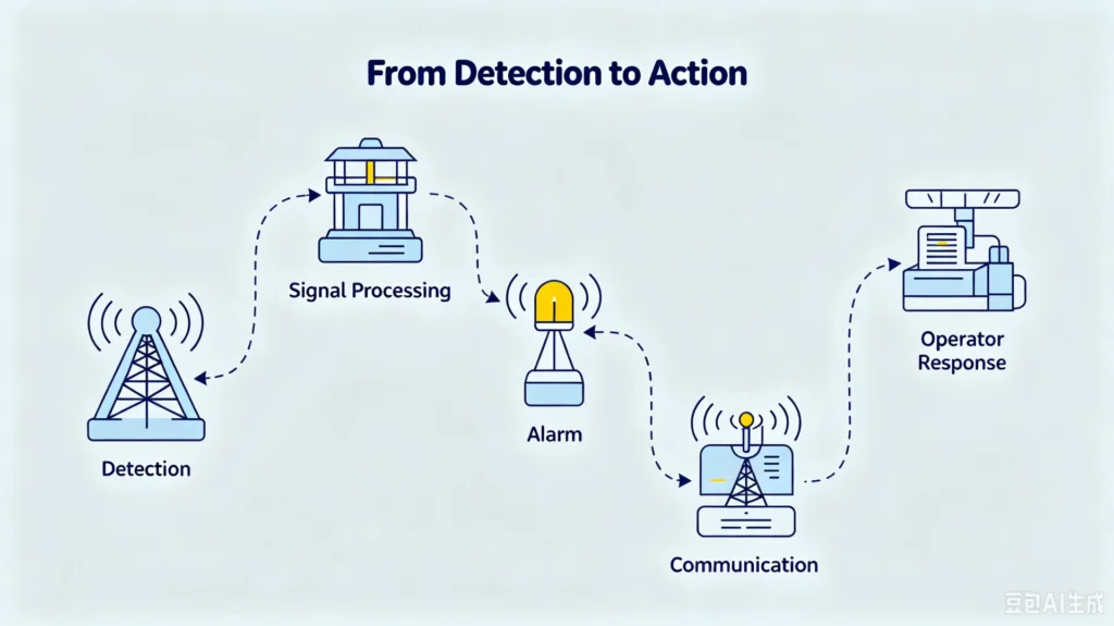
Not every site needs every block. A pole-mounted rural unit usually runs vibration plus tamper sensing, a controller and a 4G link, with the siren doing the deterrent work. A substation transformer may instead feed events straight into the existing SCADA through the controller, with no standalone platform at all. Enclosure ratings are specified per IEC 60529:1989+AMD1:1999+AMD2:2013, the IP code. A controller quoted at IP65 is dust-tight and survives water jets; IP67 survives temporary immersion to 1 metre. For detail on two of the sensing functions, see tamper and enclosure-entry detection and cable cutting detection.
How Does the Monitoring Process Work, Step by Step?
The monitoring chain runs through five steps (sensing, evaluation, local alarm, transmission and operator verification), and each step hides a design decision that separates a system operators trust from one they silence: event delays filter noise, thresholds are set per site, and event combinations raise priority before anyone drives out.
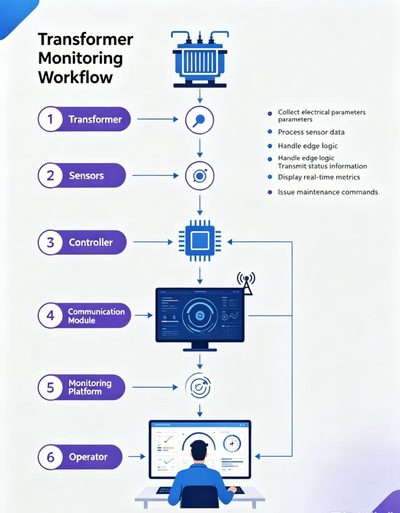
Step 1: Sensors monitor the transformer. Sensors sample continuously and hold their state. Good designs include a small event delay so that brief disturbances do not count. That filters out wind buffeting, passing traffic and livestock rubbing against a tank.
Step 2: The controller evaluates the signals. This is where quality is decided. A simple system compares each signal against a threshold and fires. A useful system combines events. Power loss followed by vibration within 60 seconds is a far stronger theft indicator than either signal alone, and the controller raises its priority accordingly. The examples below show the kind of logic a commissioning engineer configures per site.
| Condition | Threshold example | Event delay | Rationale |
|---|---|---|---|
| Tilt | More than 15 degrees | 5 s sustained | Filters wind buffeting and passing traffic |
| Vibration | Above background band | 2–5 s | Machinery nearby is the usual false source |
| Power loss | Any phase below setpoint | Held 60 s | Wait for a confirming second signal |
| Combined event | Power loss + vibration + tilt | Immediate | Escalate to security priority |
Step 3: A local alarm is generated. The siren and strobe serve two purposes: they deter opportunistic thieves on the spot, and they alert anyone within earshot. For pole-mounted units in villages this second effect is often worth more than the remote notification. Hardening measures that pair with the alarm are discussed in protecting pole-mounted transformers.
Step 4: The alarm is transmitted remotely. The communication module pushes the event by SMS, to a cloud platform, or into SCADA. The options are compared in the next section. End-to-end transmission typically completes within seconds of the event on a working cellular link.
Step 5: The operator checks the event. The platform shows which signals fired, in what order, from which site. The operator decides: dispatch a patrol, call the local contact, or log it. The system has now done its whole job. It bought the operator time and specificity.
What Does the System Detect?
Across vendors, five condition classes cover practically everything such a system reports. They are vibration (cutting, prying), tilt and movement (lifting, dragging), cable interruption, power or phase loss, and enclosure entry. Each class has its own physics and its own false-alarm profile. That is why the two hardest cases are broken out on dedicated pages: tilt and movement detection and vibration based theft detection.
What Happens When a Transformer Theft Attempt Is Detected?
Three worked examples show how event logic behaves in practice.
Example 1: movement. A tilt sensor crosses its threshold and holds. The controller fires the siren immediately and sends a tilt event. If the power-monitoring module shows the transformer still energised, the platform labels it a probable lift attempt rather than a completed theft.
Example 2: cable interruption. The cable module loses continuity on the incoming connection. Alone, that could be a fault. Combined with the loss of voltage on the affected phase, it becomes a cable-cutting event. The platform prioritises it above a simple phase alarm.
Example 3: unexpected power loss. Supply drops out with no matching protection event from the network. On its own this may be a utility outage. The controller holds it as a pending condition and escalates it if vibration or tilt follows within the configured window. This is the same event-combination logic used in transformer theft monitoring at remote substations, where power signatures carry most of the weight.
The pattern in all three: the system never announces “theft”. It announces conditions and ranks them. The decision stays with a person.
Remote Transformer Theft Monitoring: Comparing GSM, 4G and NB-IoT
All three radio options used for remote transformer theft monitoring ride licensed cellular networks, so most sites need no dedicated radio infrastructure; the real differences are bandwidth, power draw and how the link behaves in marginal coverage, which is why the choice is made per site after a signal survey rather than per project. One rule applies to all of them: coverage must be measured at the transformer location. A signal reading taken in the nearest town proves nothing about a pole in a valley.
| Option | Typical strength | Watch-outs | Typical use |
|---|---|---|---|
| GSM (SMS) | Simplest link; SMS alarms work without any IP platform | Networks are being retired; as of 2026 most European operators have shut 3G and some are closing 2G; band support (850/900/1800/1900 MHz) varies by region | Basic alarm-only sites |
| 4G Cat. 1 | IP connectivity to a cloud platform; remote configuration and alarm history | Needs a data plan, decent antenna siting and a platform subscription | Multi-site fleets with a monitoring centre |
| NB-IoT | Built for low power and deep coverage: roughly 20 dB more link budget than GPRS as a 3GPP design target, so it reaches into enclosures and difficult terrain | Low bandwidth; operator deployment still uneven by country as of 2026 | Battery-first sites and hard-to-reach locations |
Two integration notes that engineers ask about early. First, SCADA. A controller can speak IEC 60870-5-104:2006+AMD1:2016 over an IP network to a control centre. In substation platforms, events map onto IEC 61850-7-4:2010+AMD1:2020 logical nodes. Both are defined telecontrol routes, not custom engineering. Second, the platform side. Many fleets forward alarms onward by SMS and e-mail, so the site stays observable even when the main platform is down. A field-level comparison of the three radio options lives on a dedicated page. It covers which option survives which terrain: how GSM, 4G and NB-IoT compare in the field.
System vs. Traditional Security Measures
| Measure | Detects events | Notifies remotely | Main role |
|---|---|---|---|
| Fence | No (barrier) | No | Delays and deters entry |
| Lock / anti-theft hardware | No (barrier) | No | Slows the actual removal |
| Local siren alone | Only via its own trigger | No | Immediate deterrence, relies on bystanders |
| CCTV | Yes, if watched | Only when monitored | Evidence; needs power and a viewer |
| Transformer anti theft monitoring system | Yes (conditions, ranked) | Yes, within seconds | Bridges the gap between event and response |
The honest reading of this table: none of these measures wins alone. A fence slows nobody who brought bolt cutters and a truck; CCTV nobody watches is an archive, not a guard. The monitoring system earns its place by closing the notification gap, and it depends on the physical measures to actually stop whoever is coming.
Limitations: What a Transformer Anti Theft Monitoring System Cannot Do
Most buying mistakes in this category come from expecting a transformer anti theft monitoring system to do things it was never designed to do: it reports conditions rather than identifying anyone, it floods the operator with false alarms when thresholds are copied between sites, it goes silent without cellular coverage, it stops no prepared crew, and on low-risk fenced sites it may never pay back.
1. It cannot identify anyone. An alarm says a configured condition matched. It is not a verdict. The siren at 02:14 might be a theft crew or a contractor working late with wrong paperwork. Every event still ends with a human decision, which is why the operator step in the chain is not optional.
2. False alarms are a tuning problem, not a defect. Farm machinery working beside a pad-mounted tank produces genuine vibration. Grid switching transients can look like short supply dips. A system configured with one global threshold set will flood the operator until alarms get ignored, which is worse than no system. Per-site thresholds and a quarterly review of alarm history are mandatory operating work; budget for them before the purchase, not after.
3. No coverage means no notification. In valleys, dense forest or behind terrain, cellular service fails regardless of the option chosen. NB-IoT adds link budget but no operator guarantees service everywhere, and as of 2026 deployment remains uneven between countries. A coverage survey at each site is part of the design, not an afterthought. Where nothing works, the honest answer is a local-only configuration with scheduled physical inspection.
4. It complements physical security; it never replaces it. A siren scares off opportunistic theft. It does not stop a prepared crew with tools and a vehicle. A notification does not physically protect the asset while the patrol is twenty minutes out. Anti-theft bolts, locked enclosures and fencing still carry the physical load.
5. Low-risk sites may not justify the cost. A transformer inside a fenced substation with CCTV and routine patrols gains little from an add-on monitoring system. The payback case is strongest where transformers are unmanned and remote, in areas with high theft levels. That profile is discussed in rural transformer theft prevention and in regional data from theft patterns across African networks.
How Houfeng Supports Anti-Theft Monitoring Projects
Houfeng supplies the transformer anti-theft monitoring device and supports projects across the same engineering sequence this guide describes: coverage survey before communication selection, per-site threshold configuration, integration over IEC 60870-5-104:2006+AMD1:2016 or IEC 61850-7-4:2010+AMD1:2020 where a control centre exists, and documented commissioning for every alarm input.
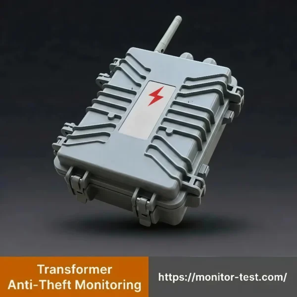
The deliverables that accompany a project follow the same pattern.
| Deliverable | What it contains |
|---|---|
| Site coverage survey | Measured signal report per installation, per band, before the radio option is fixed |
| Configuration record | Per-site thresholds, event-combination windows and the written baseline for quarterly alarm-history review |
| Commissioning checklist | Functional test of every alarm input, battery handover check, alarm path test to platform and SMS |
If you are specifying a system for unmanned sites, request a datasheet and a per-site configuration checklist for the transformer anti-theft monitoring device. Or book an engineer call to walk the selection factors in this guide against your site list.
Frequently Asked Questions
What sensors are used for transformer theft detection?
The standard set used in a transformer anti theft monitoring system is five condition sensors: vibration for cutting and prying, tilt for lifting and dragging, a tamper switch for enclosure entry, a cable-monitoring module for conductor interruption, and a power-monitoring module for supply and phase loss. Sites rarely need all five at once. Selection follows the dominant theft method in the region and the transformer’s installation type.
Can the system work when transformer power is lost?
Yes, and this is a design requirement rather than an extra: cutting supply is a standard theft step. A backup battery keeps the controller and communication module running through the outage window, and the power-loss event itself is reported as a signal. Battery autonomy in typical designs runs to days of standby, sized at specification time against the longest expected outage.
Is GSM, 4G or NB-IoT better for transformer monitoring?
There is no universal answer. It depends on what the cellular operators actually deliver at the pole. GSM with SMS is the simplest but suffers from 2G/3G network retirement; 4G Cat. 1 suits fleets with a monitoring platform; NB-IoT gives the best reach and battery life where deployed. Measure coverage at the site before choosing.
Can the system integrate with SCADA?
Yes. Over an IP network the controller speaks IEC 60870-5-104:2006+AMD1:2016 to a telecontrol centre, and in substation environments events can be mapped to IEC 61850-7-4:2010+AMD1:2020 logical nodes. Both are defined telecontrol routes, so integration is a configuration task with a protocol test, not custom software development.
Can a monitoring system be installed on existing transformers?
Retrofit is the normal case. Mechanical sensors attach to the tank and enclosure without an outage; the power-monitoring connection needs terminal access, so it is scheduled into a planned switching window. The main practical constraint is the enclosure: the controller and battery need mounting space and an ingress rating that matches the site.
Does an alarm mean a theft is in progress?
No. An alarm means a configured condition matched: vibration, tilt, power loss or a combination. Event logic raises confidence (power loss plus vibration plus tilt is far more suggestive than a single signal), but verification stays with the operator. Treat every alarm as a priority signal, not a verdict.
Conclusion and References
A transformer anti theft monitoring system works because it is a chain. Sensors watch conditions, a controller ranks events, a local alarm deters on the spot, a cellular link reports in seconds, and an operator decides. Specify it as a chain: test coverage at each site, thresholds tuned per installation, alarm history reviewed quarterly. Specified that way, it reliably shortens the distance between a theft attempt and a response. Treat it as a box that “stops thieves” and it will disappoint. The system’s honest promise is speed and specificity; the fence and the lock still do that work, and so do the people who respond.
References
- IEC 60529:1989+AMD1:1999+AMD2:2013 (Edition 2.2), Degrees of protection provided by enclosures (IP Code), International Electrotechnical Commission, official page (retrieved 4 October 2026).
- IEC 60870-5-104:2006+AMD1:2016 (Edition 2.1), Telecontrol equipment and systems — Part 5-104: Transmission protocols, IEC TC 57, IEC Webstore publication 25035 (retrieved 4 October 2026).
- IEC 61850:2026 SER (all parts), Communication networks and systems for power utility automation, IEC TC 57; event mapping per IEC 61850-7-4:2010+AMD1:2020, IEC Webstore publication 6028 (retrieved 4 October 2026).
Author: Leon Zhang, Application Engineer, Baoding Houfeng Trading Co., Ltd. He works with utilities and EPC contractors on transformer monitoring export projects.
Technical review: Houfeng engineering team (substation commissioning).
Last updated: 4 October 2026.
[…] How Does Transformer Anti-Theft Monitoring Work in Rural Networks? […]