

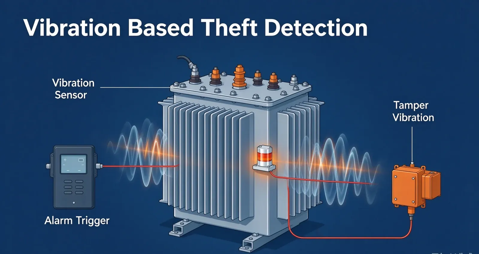
Vibration based theft detection is the practice of watching the mechanical signature of a transformer for the disturbances that a person causes, rather than the disturbances the machine causes itself, and it works because almost every theft attempt makes the steel move before the unit leaves the pole. A crew has to lean, pry, jack, unbolt or lift, and each of those actions puts energy into the tank, the base or the support structure, where a sensor can feel it.
Key Takeaways
- The method reads change, not level. A vibration alarm is triggered by the difference between today’s signature and the unit’s own learned baseline, which is why the baseline matters more than the sensor.
- Normal vibration is load-correlated and continuous. Theft-related vibration is crew-correlated, arrives in bursts, and stops when the work stops.
- Forced removal is not one impact. It is an ordered sequence of disturbance, and the sequence is predictable enough to design around.
- Vibration covers the stage where the unit is being worked on. Cable cutting, tilt and enclosure switches cover the stages before and after it.
- The limits are real: mounting decides what the sensor can hear, weather sets the false-alarm floor, and no vibration rule can name the person who caused the event.
What Is Vibration Based Theft Detection?
Vibration based theft detection is a monitoring method that measures mechanical movement on a transformer and its support structure, learns what the unit normally sounds like under load, and raises an event when the measured pattern departs from that learned baseline in a way associated with unauthorised work. It is not the same discipline as condition monitoring, which watches vibration to diagnose mechanical health. Here the machine is assumed healthy; the question is whether a person has started to touch it.
The distinction changes almost every design decision. A condition-monitoring programme tunes sensors to bearing and winding frequencies, because that is where mechanical faults announce themselves. A theft programme tunes to the low-frequency transients that tools and human effort produce, and it accepts that the useful evidence is short-lived rather than continuous. [UNIQUE INSIGHT] The useful mental model is that the transformer has a voice, and theft detection is listening for the moment somebody else touches it.
Both disciplines can share one sensor on one tank, but they cannot share one alarm rule. A condition rule that waits for a trend to develop will sleep through a thirty-second prying attempt, and a theft rule set sensitive enough to catch that prying will cry wolf on every storm. Keeping the two rule sets separate is the first engineering decision on any site where the same hardware serves both purposes.
| What the method watches for | Purpose | Typical output |
|---|---|---|
| Trend in mechanical condition | Diagnose faults inside the machine | Maintenance recommendation |
| Departure from a load baseline | Detect unauthorised physical work | Event and alarm |
The transformer anti-theft monitoring system page shows how that event is combined with the other signals on the same unit.
Normal vs Abnormal Transformer Vibration
Abnormal transformer vibration is separated from normal vibration by three properties rather than by a single amplitude figure, because a healthy transformer is never quiet: it hums at the supply frequency and its harmonics, and that hum rises and falls with load, so amplitude alone tells an operator almost nothing. The three properties that matter are how the vibration relates to load, how it behaves over time, and whether it stops when the load does not.
| Source | Frequency and character | Correlation | Interpretation |
|---|---|---|---|
| Magnetostriction in the core | Twice line frequency, steady, tonal | Follows supply and load | Normal |
| Cooling fans and pumps | Broadband, steady while running | Follows fan control | Normal |
| Winding movement under load | Low-level, load-linked | Follows current | Normal |
| Weather on the tank and fittings | Broadband, gusty | Follows wind and rain | Nuisance, not a threat |
| Impact from a tool or a dropped part | Sharp onset, wideband burst | No load link | Interference candidate |
| Prying, jacking or dragging | Irregular, sustained, low frequency | Tied to human effort, not to load | Interference candidate |
The third row of the normal group is the reason a baseline is needed at all. Because the healthy hum itself moves with load and with ambient temperature, a fixed threshold set on a mild day will either miss a real event on a cold night or fire every afternoon in summer. A learned baseline that tracks load and temperature keeps the comparison fair, which is exactly what the evaluation approach in ISO 20816-1:2016 sets out for machines in general: judge vibration magnitude and the change in vibration against defined operating conditions, not against an arbitrary number. The tonal content that makes this baseline stable is characterised through sound-level measurement as set out in IEC 60076-10:2016, which is why the normal signature can be learned in the first place.
The last two rows are the ones this page cares about, and they share a property that makes them detectable. Human work is discontinuous. A person leans, stops, repositions, leans again. The resulting signal is bursty and irregular in a way that no load-driven source is, so the pattern, not the peak, is the discriminator.
Theft Related Vibration Signals: What to Look For
Theft related vibration signals fall into four families, and each one corresponds to a physical action a crew must perform, so a specification that names all four is checking the sensor against the whole removal sequence rather than against one dramatic event. Two of the families are loud and easy, one is slow and quiet, and one is rhythmic in a way that is almost impossible to imitate by accident.
| Signal family | Physical cause | Signature | Why it is catchable |
|---|---|---|---|
| Impact transient | Hammer, bar, dropped tool | Sharp onset, broad frequency, under a second | High energy in a band the load hum does not occupy |
| Prying and levering | Bar against a cover or base | Irregular low-frequency bursts, repeated | Repeats with human effort, not with load |
| Slow forced movement | Jacking, dragging, tilting | Low-frequency drift below the hum band | Visible as a baseline shift over minutes |
| Rhythmic tool work | Sawing, wrenching, repeated strikes | Regular repetition at hand speed | The rhythmic pattern has no load explanation |
Rhythmic tool work is the most distinctive of the four and the most useful in practice. A person turning a wrench produces a repetition rate in the range of human hand movement, and nothing in a healthy transformer repeats at that rate, so a rule that looks for periodic bursts in the one-to-three-hertz band will separate a crew from an engine. The reasoning is the same as any correlation rule: find the feature that the innocent sources cannot produce.
[PERSONAL EXPERIENCE] The signal that proved most reliable on rural units was not the loudest one. It was the slow forced movement of the third family, because a crew that has already cut the cables has no reason to hurry, and the jacking phase is long enough that a baseline-shift rule catches it where an impact threshold would see nothing unusual at all. That lesson is why the least dramatic rule often earns its place in a vibration based theft detection scheme.
The Forced Removal Vibration Signature
A forced removal vibration signature is the ordered set of disturbances left by the physical steps of taking a transformer off its mounting, and it is worth describing as a sequence rather than as a single event because the sequence tells an operator where the crew is, not merely that something is happening. Each step has its own amplitude, duration and repetition, and each fits a different detection window.
| Step | What the crew does | Vibration character | Best detection window |
|---|---|---|---|
| Releasing fixings | Unbolts or cuts mounting hardware | Short repeated impacts, rhythmic | Burst and rhythmic rules |
| Breaking the base free | Pries the unit from its plinth | Irregular low-frequency bursts | Prying rule with a sustained threshold |
| Raising the unit | Jacks or levers one side | Slow drift in level and attitude | Baseline-shift rule, paired with tilt |
| Dragging or rolling | Moves it off the pad | Broadband, sustained, direction-linked | Sustained-event rule |
| Loading | Winches or lifts onto a vehicle | Long, irregular, sometimes minutes apart | Duration window, not peak |
The value of writing the sequence down is that it turns a vague requirement into a placement decision. If the risk profile for a district is dominated by crews who remove units carefully at night, then the rules that earn their keep are the slow-drift and rhythmic ones, and the sensor has to be mounted where a jack’s load actually passes. If the risk is dominated by fast smash-and-take attempts, the impact rule carries the programme. The two risk profiles do not need the same tuning, and treating them as one is how a specification ends up with rules that fit neither. The tilt detection page covers the attitude change that accompanies the third step.
How Does Vibration Monitoring Detect Transformer Theft?
Vibration monitoring detects theft by comparing a live signature against a baseline the unit has learned for itself, and because the comparison runs continuously the chain from disturbance to alarm completes without anyone watching the site or answering a prompt at the control room. Six links make up that chain.
- Learn the baseline. The controller records vibration against load and ambient temperature for a period long enough to see a full weather cycle, so that normal variation is captured rather than mistaken for an event.
- Measure continuously. The sensor samples the tank, base or support at a rate high enough to resolve short transients, rather than slow trends alone.
- Compare with the baseline. The live signature is judged against the learned envelope for the current load and temperature, not against a fixed number.
- Apply rules. Impact, rhythmic, drift and duration rules each test the signal for their own pattern. A single rule rarely carries a site on its own.
- Confirm. A candidate event is checked against the other signals on the unit so that a maintenance activity and a theft attempt can be told apart.
- Alarm and record. A local output fires, the event is timestamped, and the record travels over the site link using the chain described on the transformer theft detection page.
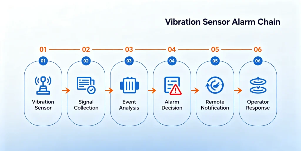
Figure 1. The sensing chain behind a vibration-based theft alarm, from sensor to remote notification.
The third link is where a vibration programme succeeds or fails. A threshold set by hand on the day of commissioning is wrong by the following season, because the baseline moves with temperature and load. A controller that keeps relearning the envelope stays comparable across the year, and it also lets a site change its load pattern, which rural irrigation transformers do every season, without a technician visit.
How to Reduce False Alarms in Vibration Monitoring
False alarm reduction in vibration monitoring starts from the fact that its nuisance sources are different from those of a switch-based detector, because a vibration sensor hears weather, animals, traffic and neighbouring machines, none of which opens a door or cuts a cable. The work is therefore to build a filter chain that lets the four theft signal families through while stopping the rest.
| Apparent event | What the sensor sees | How to separate it |
|---|---|---|
| Wind and rain on the tank | Broadband gusty energy | Duration and pattern rules; weather correlation is the main nuisance task in any vibration based theft detection scheme |
| Animals on the structure | Isolated impacts, daytime or dusk | Amplitude floor and event spacing |
| Neighbouring machinery | Steady tonal energy | Frequency selectivity, baseline inclusion |
| Traffic and ground-borne vibration | Low-frequency, source-correlated | Mounting isolation and direction |
| Seasonal baseline drift | Slow change in the whole envelope | Continuous re-learning of the baseline |
| Routine maintenance | Impact and rhythmic signals that look real | Work-permit flag and confirmation step |
Two practices do most of the work in a vibration based theft detection programme. The first is that the baseline must keep learning, because a fixed envelope drifts out of date and then either sleeps or cries. The second is that a single vibration event should not alarm on its own; it should be confirmed against a second signal, a work permit or a duration test before it escalates. Correlation is nearly free when the unit already carries cable, tilt or enclosure sensing, and it removes most of the nuisance events that would otherwise train operators to ignore the system.
Choosing Vibration Sensors and Mounting Points
Choosing a vibration sensor and choosing where to mount it are the same decision, because the mounting path decides which disturbances reach the element and which are absorbed before they arrive, so the placement is settled by the physical route a crew’s force takes through the unit. Three sensor families cover most theft work.
| Sensor family | What it responds to | Best for | Blind spot |
|---|---|---|---|
| Accelerometer | Acceleration across a wide band | Short impacts and rhythmic work | Needs firm mounting or it reads its own resonance |
| Velocity sensor | Vibration velocity at low frequency | Slow drift and sustained movement | Less sensitive to very short impacts |
| Shock or impact sensor | Discrete mechanical events | Simple, low-power installations | Reports that something happened, not what |
Placement matters more than the part number. A sensor on the tank wall hears prying on the cover but may miss a jack under the base. A sensor on the plinth hears jacking and dragging but is deaf to work on the bushings. A sensor on the support structure hears the whole unit move but also hears the wind that shakes the pole. The rule that resolves this is to place sensing along the route the force travels, and to accept that one mounting point cannot cover every step of the removal sequence. Most programmes end with two points: one on the body, where tool work lands, and one on the base or support, where jacking and dragging begin. For the environmental side of the specification, a device type-tested to IEC 60068-2-6:2007 has been verified against sinusoidal vibration at defined severities, which settles the robustness question and leaves the detection logic to be judged separately.
Combining Vibration With Cable, Tilt and Tamper Signals
Vibration detection should not run alone, because it covers one stage of a sequence and its most convincing alarms come from a second signal that agrees, so the honest way to place it is as the stage that catches the unit being worked on. Each signal owns a moment, and the moments line up in the order a crew works.
| Signal | Stage it covers | Where it is described |
|---|---|---|
| Cable continuity | Cables cut before the unit is touched | The cable cutting detection page |
| Vibration | Prying, jacking and tool work on the unit | This page |
| Enclosure and tamper switch | Cabinet or cover opened | The tampering detection page |
| Tilt | The unit raised or leaned | The tilt detection page |
| Loss of supply | Confirmation that the unit is isolated | The theft detection overview |
The design rule is to correlate rather than to duplicate. A vibration burst followed by a tilt change is a pattern that wind does not produce, while a vibration burst alone on a stormy ridge is a pattern that a field crew will learn to ignore within a season. Two correlated signals carry more weight than either can alone, and the combination is what turns a nuisance into a credible event.
Limitations of Vibration Detection
Vibration detection has hard limits, and writing them into the specification before the hardware is ordered is the fastest way to build a programme that field crews keep trusting through its first season in service and its first nuisance alarm. A detector that is oversold produces a fleet that operators silence, which is worse than no detector at all.
- It reports movement, not intent. A vibration event says the steel moved. It cannot say whether a person, an animal or the wind caused it, and it cannot identify anyone.
- Placement caps the coverage. A sensor hears what its mounting can transmit. Every point it does not cover is a documented gap, not a hypothetical one, and gaps should be listed rather than assumed away.
- The baseline drifts and must keep learning. A fixed threshold goes out of date with temperature and load. Without continuous re-learning, the system either misses events or floods the operator.
- Weather sets the false-alarm floor. On an exposed ridge, wind produces real vibration that no rule can fully separate from low-level interference. Sensitivity has to be traded against nuisance rate.
- It competes with the outage it detects. Many attempts involve a loss of supply, so the controller and its backup power have to survive that outage to report the event.
- Mounting quality decays. Loose brackets, corrosion and water ingress reduce the signal over time, and a degraded sensor often fails quietly rather than loudly.
| Limitation | Can design reduce it? | How |
|---|---|---|
| Reports movement, not intent | No | Correlate with cable, tilt and enclosure signals |
| Placement caps coverage | Yes | Route sensing along the force path; document gaps |
| Baseline drift | Yes | Continuous re-learning of the envelope |
| Weather nuisance | Partly | Duration rules and a second correlated signal |
| Outage conflict | Yes | Battery backup and on-device event storage |
| Mounting decay | Yes | Scheduled inspection of brackets and seals |
Five of the six rows can be improved at design time, and only the first is permanent. The theft prevention guide covers the physical hardening that buys the detection system the seconds it needs.
How Houfeng Delivers the Detection Programme
Houfeng scopes a vibration programme around the removal sequence a district actually faces, rather than around a fixed sensor package, because the rules that catch a careful night-time crew are not the rules that catch a fast smash-and-take. The delivery sequence below is the same for a single unit and for a district rollout.
- Site survey. Each unit is walked, the mounting and support structure are recorded, and the force paths a crew would use are identified so the sensing points can be placed along them.
- Baseline capture. A real baseline is recorded against load and ambient temperature over a full weather cycle, so the reference the controller learns is the site’s own, not a factory default.
- Rule set. Impact, rhythmic, drift and duration rules are configured for the district’s risk profile, with confirmation rules that draw on cable, tilt and enclosure signals where those exist.
- Local and remote outputs. A local output is configured alongside the remote path, so an event survives a failed link, and the escalation list is exercised with a live test alarm.
- Commissioning and handover. Each sensing point is tested with a deliberate disturbance, the baseline and rule set are handed over with the drawings, and the response procedure is agreed with the operator.
The reference unit for these signals is the HF-T-609 transformer vibration monitoring system, which combines vibration sensing with the correlated inputs above on one controller so that the confirmation rules can run without a separate gateway.
Frequently Asked Questions
How does vibration monitoring detect transformer theft? Vibration based theft detection works by learning the signature a transformer produces under normal load, then comparing every subsequent reading against that baseline. A prying, jacking or tool event departs from the baseline in a pattern that load-driven vibration cannot produce, so the controller raises an event when the pattern matches a theft rule and a second signal agrees.
Normal vs abnormal transformer vibration: how are they told apart? By three properties, not by amplitude. Normal vibration is load-correlated, continuous and tonal; theft-related vibration is crew-correlated, bursty and irregular, and it continues when the load does not change. Because the healthy hum itself rises and falls with load and temperature, the comparison has to use a learned baseline rather than a fixed threshold.
What vibration signals indicate tampering? Four families: short impact transients from tools, irregular low-frequency bursts from prying, slow drift from jacking or dragging, and rhythmic repetition at human hand speed. The last is the most distinctive, because nothing inside a healthy transformer repeats at the rate a person turning a wrench produces.
Can vibration detection work on unattended transformers? That is where it earns most, because there is no witness on site and the inspection interval is long. The controller has to learn its own baseline without a technician, carry a local alarm output for the moment the communication link is down, and store events across the outages that accompany many attempts.
How many sensors does one transformer need? Most programmes settle on two points: one on the body, where tool work lands, and one on the base or support, where jacking and dragging begin. One point cannot cover the whole removal sequence, because a sensor can only hear what its mounting transmits, but two well-placed points usually cover the steps that matter.
How can false alarms be reduced? By letting the baseline keep learning, by requiring a candidate event to pass a duration or pattern test, and by confirming it against a second signal such as cable continuity, tilt or an enclosure switch before it escalates. Sensitivity alone cannot separate wind from a crew, so the logic has to.
Conclusion and References
Vibration based theft detection works because a crew must move steel before it can take steel, and that movement is a signal a belt-and-brace programme can learn to recognise. The engineering is in the baseline, the rule set and the correlation, not in the sensor. The distribution transformer theft page describes what the losses look like when none of it is in place. Get the sensing points onto the force path, let the baseline track the seasons, and require a second signal to agree before the alarm escalates, and the unit reports that it is being worked on while the crew is still beside it.
If you are scoping a district rather than a single unit, send us your requirement with the site list and the loss record for each area. An application engineer will return a per-site sensing and rule plan built around the HF-T-609 unit, and you can request a datasheet for the reference configuration first.
Sources
- ISO 20816-1:2016, Mechanical vibration — Measurement and evaluation of machine vibration, Part 1: General guidelines. ISO
- IEC 60076-10:2016, Power transformers, Part 10: Determination of sound levels. IEC Webstore
- IEC 60068-2-6:2007, Environmental testing, Part 2-6: Tests, Test Fc: Vibration (sinusoidal). IEC Webstore
Written by the engineering content team at Baoding Houfeng Trading Co., Ltd., which works with utilities, EPC contractors and industrial operators on transformer monitoring and protection projects. Technically reviewed by [Reviewer name], senior protection and metering engineer, [X] years in distribution network operations (to be confirmed by the client). Last updated: 4 October 2026.