

Transformer theft detection is the practice of identifying a theft attempt on a distribution transformer while it is happening, through sensors that convert vibration, tilt, enclosure opening, cable interruption and power loss into events, and through alarms that carry those events to someone who can act. Done well, it shortens the gap between the crime and the response from days to minutes. Done badly, it produces noise that the operations team learns to ignore. This page explains how the detection chain works, what each sensor type senses, how alarms and remote reporting behave in the field, and where detection reaches its limits. The crime itself and the parts that get taken first are covered in the guide to distribution transformer theft, and the full protection stack is covered in the guide to transformer theft prevention.
Key Takeaways
- Detection is a chain, not a sensor: sense, judge, alarm locally, report remotely, respond. The weakest step sets the value of the whole chain, and the last two steps are organisational, not technical.
- Match the sensor to the method. Vibration, tilt, door state, cable continuity and supply status each see one or two theft signatures and are blind to the rest.
- Two correlated signals beat one sensitive signal. Single-sensor layouts are cheap and noisy; event-combination logic costs seconds and removes most nuisance alarms.
- False alarms decide whether the programme survives its first year. Thresholds are set per site at commissioning and reviewed after the first storm season.
- Remote reporting is a coverage problem before it is a technology problem. Survey the signal at each pole before choosing GSM, 4G or NB-IoT.
What Is Transformer Theft Detection?
Theft detection answers a narrower question than prevention: not how to stop a crew from reaching the unit, but how to make sure somebody knows within minutes when they do. It converts physical events at the transformer, vibration, movement, enclosure opening, cable interruption and loss of supply, into an alarm that reaches a responsible person.
The distinction matters when budgets are written. Prevention makes the attempt harder or noisier; detection assumes the attempt is happening and optimises the minutes that follow. The two only work as a pair, because an alarm with no responder behind it is documentation, not protection. [UNIQUE INSIGHT] On the sites we review, the most common failure is not a missed event but an event that reached three phones and no duty roster.
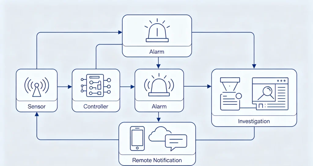
Figure 1. The operating chain of a transformer security system: detection, alarm logic, communication, power, monitoring and response, in sequence.
How the Detection Chain Works, Step by Step
Every detection chain follows the same five steps, sense, judge, alarm locally, report remotely and respond, and the chain is only as strong as its weakest step, because a sensor that fires accurately is worthless if the alarm reaches nobody, and a perfect notification is worthless if no responder is on duty at that hour.
- Sense. Transducers convert physical phenomena, acceleration, inclination, door state, continuity, supply voltage, into electrical signals. Sensor placement matters as much as sensor choice: a vibration sensor bolted to the plinth sees a different world from one bolted to the cover, and a door switch on the LV compartment does not watch the HV bay.
- Judge. The controller applies thresholds and event-combination windows, deciding whether a signal pattern deserves an alarm.
- Alarm locally. A siren or strobe fires at the site to interrupt the attempt and attract witnesses.
- Report remotely. The controller pushes an event record over the cellular network to a platform, an SMS list or a control centre.
- Respond. A named person verifies the event against context and dispatches, or documents a false alarm.
| Event | Detection method | Typical alarm condition | Failure mode if unconfigured |
|---|---|---|---|
| Enclosure opened | Door switch or tamper switch | Door event without a matching work order | Crews learn to open panels quietly |
| Tank cut or pried | Vibration sensor | Sustained vibration above threshold | Grid switching or farm machinery masks real cuts |
| Unit lifted or toppled | Tilt sensor | Inclination beyond set angle | Slow movement on soft ground stays under threshold |
| Cable or earthing stripped | Continuity monitoring | Circuit interruption on monitored loop | Advance cutting days before the lift reads as a fault |
| Supply lost | Power-loss monitoring | Mains absence with battery present | Normal outages alarm identically to theft |
The last column is why commissioning is a site-by-site job. The same hardware produces a working chain on one pole and a noise generator on the next.
Transformer Theft Sensors: What Each Type Senses
Transformer theft sensors divide by the physical signature each theft method leaves, vibration for cutting and prying, tilt for lifting or toppling, door state for enclosure opening, continuity for cable and earthing theft, and supply status for the moment the unit goes dead. Match the sensor to the method that dominates in your own incident record, not to the longest spec sheet.
| Sensor | Senses | Best suited to | Blind spot |
|---|---|---|---|
| Vibration | Cutting, prying, drilling on the tank | Pad-mounted and ground-level units | Slow hand work; ambient vibration sites |
| Tilt | Lifting, toppling, removal from plinth | Pole-mounted units on hooks and chains | Gradual settling; rotation without tilt |
| Door / tamper switch | Panel and cover opening | Any compartment with removable covers | Anything that bypasses the cover |
| Cable continuity | Earth lead and LV cable theft | Sites with repeated earthing theft | Theft that leaves conductor intact |
| Power loss | Supply interruption at the unit | The moment of a load-side theft | Ordinary outages; needs backup supply |
No single transformer theft sensor sees every method, which is why the table pairs each one with its blind spot. Continuity monitoring deserves its own reading, because organised crews increasingly cut and strip conductors days before they return for the unit. The dedicated page on cable cutting detection covers that signature in depth.
How Does a Transformer Theft Alarm Work?
A transformer theft alarm fires when the controller sees a configured event combination, and what has to be true before it fires is the design decision that matters: single-signal alarms respond fast and false-alarm often, while two correlated signals cost a few seconds and remove most of the noise.
Local output comes in two forms, and they serve different purposes. An audible siren interrupts the attempt and pulls witnesses; a strobe does the same where noise bylaws apply. Both are deterrence devices, not detection devices, and both are useless on a site nobody passes. The same alarm condition therefore usually branches two ways. The siren stays at the pole for opportunistic crews; the notification goes off-site for the ones who wear gloves.
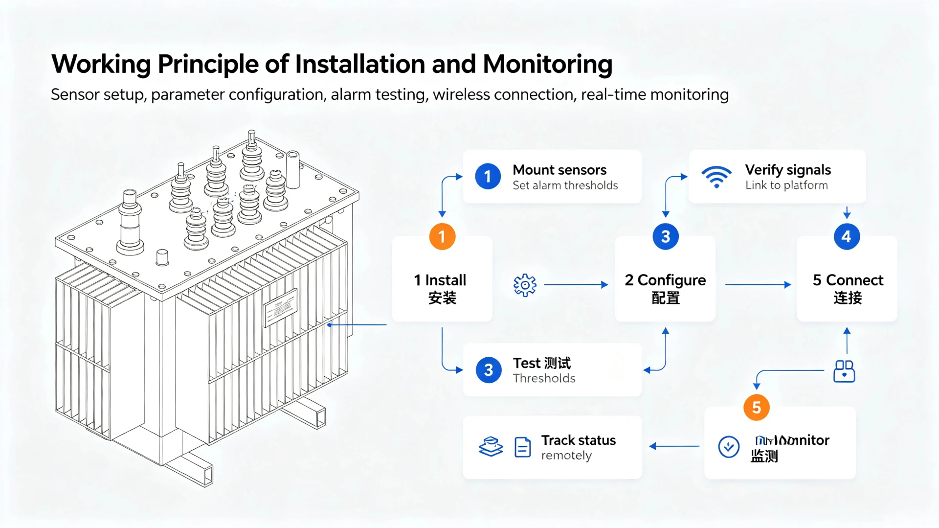
Figure 2. The alarm path of the chain: sensor signals reach the controller, which drives the local alarm, remote notification and the investigation that follows.
[PERSONAL EXPERIENCE] On district rollouts the alarm split has been the single most argued-over setting: operations teams want everything silent and reported, patrol teams want the siren, and the workable answer has usually been siren on high-risk poles, silent notify everywhere else, revisited after the first quarter of alarm history.
Remote Transformer Theft Detection
The remote half of the chain moves an event off the site, and it matters because most distribution transformers sit where no employee ever passes, so what has to travel is a compact event record rather than a video feed.
The record carries sensor identity, event type, timestamp, signal strength and supply status. That is deliberately little data. Small records survive weak links, queue during outages and cost almost nothing to store for years, which is what an evidentiary trail needs; a video-first design would demand bandwidth and power that most poles do not have. Delivery targets split three ways: a monitoring platform for teams that work from dashboards, SMS lists for districts without platform integration, and a control centre over a telecontrol protocol where SCADA exists. Where coverage is intermittent, the controller has to store events locally and forward them when the link returns. A site at the edge of a cell reports intermittently, and intermittent reporting looks exactly like a faulty sensor.
The full monitoring layer, platform, thresholds and response workflow, is described in the guide to the transformer anti-theft monitoring system. This page stays with the detection half of that system.
Transformer Theft Detection Using GSM, 4G and NB-IoT
The choice between GSM, 4G and NB-IoT comes down to one trade, coverage against consumption, and the right answer is set by the site, not by the technology. GSM suits legacy networks and low data volumes, 4G suits sites that need headroom for richer reporting, and NB-IoT suits deep-indoor, low-power reporting where 2G has been or is being switched off.
| Communication path | Typical strength | Watch out for |
|---|---|---|
| GSM / 2G | Mature coverage, cheap modules, tiny data volumes | 2G and 3G sunset in many countries; do not design new deployments on it |
| 4G LTE | Headroom, low latency, firmware updates over the air | Higher idle consumption; plan solar sizing accordingly |
| NB-IoT | Deep penetration, multi-year battery life | Uneven national deployment as of 2026; no service guarantee in terrain |
| Dual-path (LTE + NB-IoT) | Fallback when one network degrades | Cost and commissioning complexity per site |
The 2G and 3G sunset deserves a planning paragraph of its own, because it catches fleets mid-life. Devices ordered years ago on GSM stop reporting when the operator refarms the band, and the failure looks like a hardware fault. When buying, ask the supplier which paths the controller carries and whether the radio module is replaceable; when auditing an installed fleet, list each site’s current network and the operator’s published shutdown date before the budget cycle, not after the first silent season.
Where events feed a control centre rather than a web dashboard, the reporting side normally speaks IEC 60870-5-104:2006+AMD1:2016, the telecontrol protocol standard for network access in SCADA systems (official standard page, retrieved 4 October 2026). Confirming that the device supports the profile your control centre runs is a five-minute check that avoids an integration project later.
Single-Sensor or Multi-Sensor: Choosing the Detection Layout
The choice between a single sensor and a multi-sensor layout is a choice between two failure modes, missing an event and drowning in false alarms, and multi-sensor correlation is the only way to reduce both at once. Start single-sensor where the dominant method is known, and go multi-sensor where sites are exposed or crews are organised.
| Layout | Detects well | Main limitation |
|---|---|---|
| Vibration only | Fast cutting and prying | Nuisance alarms on busy or windy sites |
| Tilt only | Lifting and removal | Misses everything that happens before the lift |
| Vibration + door state | The cutting-then-opening sequence | Needs a commissioning window tuned per site |
| Full multi-sensor + power | The whole transformer theft detection event chain, including the outage | Highest cost; justified on the highest-value units |
Correlation logic is what turns two cheap sensors into a reliable one. A vibration event alone might be a lawnmower; a vibration event followed by a door event inside a sixty-second window almost never is.
False Alarms and Detection Reliability
False alarms, not hardware cost, decide whether a detection programme survives its first year, because an operations team that receives ten nuisance alerts learns to ignore the eleventh, which may be real, and any threshold that fires each time a fitter opens the door will be disabled by the fitters themselves.
| Cause | Looks like | Fix |
|---|---|---|
| Farm machinery beside the unit | Sustained vibration events | Site-specific vibration threshold; time-of-day arming |
| Grid switching transients | Brief supply dips and spikes | Debounce windows on power-loss alarms |
| Contractors with legitimate access | Door events at odd hours | Work-order whitelist on the door channel |
| Edge-of-cell coverage | Intermittent reporting, stale heartbeats | Coverage survey; antenna siting; store-and-forward |
| Storm season | Everything at once | Review thresholds after the first storm season, not before |
[PERSONAL EXPERIENCE] The districts that kept their programmes running all did the same thing: they treated the first month of alarm history as commissioning data, tuned from it, and only then published the response procedure everyone had to follow.
Reliability is measurable, and the measurement is operational, not laboratory accuracy. Two numbers matter: the share of alarms that led to a correct response, and the share of real events that produced an alarm. Both are read straight from the alarm history against the incident record, and both belong in the quarterly review alongside the threshold changes that were made and why.
How to Choose and Commission a Transformer Theft Detection System
A system is chosen in six steps, and the order matters: identify the dominant local method, match the installation form to the transformer type, verify cellular coverage at each pole, decide who receives alarms and how, check backup power for the outage that accompanies the theft, and rate the enclosure for the environment.
The steps in practice:
- Method first. Read the incident record; fit the sensors the dominant method exposes.
- Installation form. Pole-mounted, pad-mounted and substation units take different mounts and different sensor positions.
- Coverage. A measured signal report per site, per band, before any radio is fixed.
- Alarm routing. Who receives, on what channel, with what escalation when the first phone does not answer.
- Backup power. The theft often starts by cutting supply; battery sizing decides whether the chain survives its own trigger.
- Environment. Ingress rating, temperature range and solar budget for the worst month, not the average one.
| Deliverable | What it contains |
|---|---|
| Site coverage survey | Measured signal report per installation, per band |
| Configuration record | Per-site thresholds, event-combination windows, alarm routing list |
| Commissioning checklist | Functional test of every input, battery handover check, end-to-end alarm path test |
Maintenance is one recurring item: review alarm history quarterly and after every storm season, and re-tune anything that produced alerts nobody acted on. A device left at factory thresholds for two years is not a working detection system.
If you are scoping a district rather than a single unit, send us your requirement with the site list and the inspection interval for each site. An application engineer will return a per-sensor layout, a communication recommendation and a configuration checklist, and will flag any site with no workable reporting path before hardware is ordered. You can also request a datasheet for the reference configuration first.
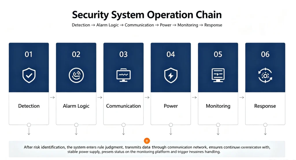
Figure 3. Installation and commissioning workflow for a detection device: mount and set thresholds, test, verify the link to the platform, then track status remotely.
For a reference configuration, the transformer anti-theft monitoring device bundles vibration, tilt and door inputs with GSM, 4G and NB-IoT reporting and battery backup in one enclosure, which covers steps two through five for most distribution sites.
Limitations: What Transformer Theft Detection Cannot Do
Detection has hard limits that sales material tends to blur, and naming them is the fastest way to scope a programme that survives contact with operations: it cannot stop a crew by itself; it reports conditions and cannot identify people; it fails without power and coverage; and its accuracy is an operating outcome, not a spec-sheet number.
1. It cannot stop the crew. A siren adds seconds of delay and a chance of witnesses, and that is all. A prepared crew with tools and a vehicle finishes anyway, so physical hardening and hardware still carry the load, per the prevention guide.
2. It cannot identify anyone. An alarm only says a condition matched, not who matched it. Every event still ends with a human decision.
3. No power and no coverage mean no notification. The theft often begins by cutting supply, and sites in valleys or dense forest may have no workable cellular path at all. Where neither works, the honest design is a local-only siren with scheduled physical inspection, which requires accepting slower response.
4. Accuracy is earned per site. The same device is reliable on one pole and noisy on the next, because ambient vibration, coverage and visitor traffic differ. Published accuracy figures describe the lab, not your feeders. Risk also varies enormously by region, so regional loss data such as the African networks overview should set expectations before any equipment is quoted, and the incident record should override both the vendor and the regional average.
Frequently Asked Questions
How does transformer theft detection work? A detection chain converts physical events at the transformer, vibration, tilt, door state, continuity loss and supply loss, into controller decisions, local alarms and remote event records. The chain only works end to end: a correct sensor signal is worthless if the alarm reaches nobody, and a delivered notification is worthless if nobody is rostered to respond.
What sensors are used for transformer theft detection? Five types cover the documented methods: vibration sensors for cutting and prying, tilt sensors for lifting, door or tamper switches for enclosure opening, continuity monitoring for cable and earthing theft, and power-loss monitoring for the outage that accompanies most attempts. Multi-sensor combinations with event-correlation logic reduce false alarms substantially compared with any single sensor.
How does a transformer theft alarm work? The controller compares incoming sensor signals against thresholds and event-combination windows set during commissioning. When a condition or combination matches, it drives the local siren or strobe and pushes an event record to the platform, SMS list or control centre. Two-signal logic, vibration followed by door opening within a set window, is the standard way to keep nuisance alarms down.
Can detection still work after the transformer loses power? Yes, and it has to, because cutting supply is often the first move. The controller and sensors run on an internal battery sized for the outage window, and the power-loss event itself is one of the alarm conditions. Battery state is reported with every heartbeat so a dead battery never goes unnoticed. Ask any supplier for the battery’s reporting life at your climate temperature, not at the standard’s reference temperature, because cold weather shortens it sharply.
Can sensors be retrofitted on existing transformers? In most cases yes. Vibration, tilt and door sensors mount on the tank, cover and plinth without de-energising the unit, and the controller takes supply from the LV side with battery backup. Retrofit jobs also need the same six selection steps as new installs, because an old unit in a new trouble spot still needs the method-first decision. The question that actually takes planning is cellular coverage at that specific pole, not the sensors.
What is the difference between detection and prevention? Prevention makes the attempt harder and noisier through fencing, hardware and locked compartments; detection assumes an attempt is under way and optimises the minutes between the first signature and the response. Budgets that fund only one of the two tend to buy hardware without an answer, or alarms without a fence.
Conclusion and References
Theft detection is a chain of five steps, and the two specification pages that matter most are the last ones: who receives the alarm, and what happens next. Match sensors to your own incident record, prefer two correlated signals to one sensitive one, survey coverage before choosing a radio, and budget the commissioning time that turns hardware into a working system. That is the whole discipline; the rest is installation detail.
References
- IEC 60870-5-104:2006+AMD1:2016, Telecontrol equipment and systems — Part 5-104: Transmission protocols, IEC TC 57. official standard page (retrieved 4 October 2026).
- IEC 60529:1989+AMD1:1999+AMD2:2013, Degrees of protection provided by enclosures (IP Code), IEC TC 70; ingress rating context for outdoor enclosures (text citation).
- IEC 60076-1:2011, Power transformers — Part 1: General, IEC TC 14; rating context for the units discussed (text citation).
Reviewed by [Reviewer name], [X] years in distribution network operation and maintenance.
Written by the engineering content team at Baoding Houfeng Trading Co., Ltd., works with utilities, EPC contractors and industrial operators on transformer monitoring and protection projects. Technically reviewed by [Reviewer name], senior protection and metering engineer, [X] years in distribution network operations (to be confirmed by the client). Last updated: 20 September 2026.