

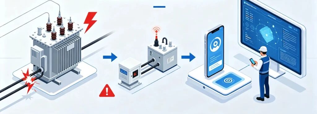
Transformer cable cutting detection is the practice of watching the cables that serve a transformer for the moment one of them is cut, and it exists because cutting comes before lifting in almost every theft of a distribution unit on record. The method watches circuit continuity rather than voltage or current, so it can raise an alarm seconds after the cut instead of after the outage that follows it. That difference in timing is the whole commercial argument for the technique.
Key Takeaways
- The cables around a transformer are not interchangeable. A cut primary cable blacks out the load, a cut secondary cable leaves the unit looking normal, and a cut grounding conductor leaves no electrical trace at all.
- Continuity supervision is what makes a cut visible. An unsupervised loop can be silenced with a jumper, which is why the loop design matters more than the sensor part number.
- A cable alarm is a status change, not a verdict. It tells an operator that the circuit opened, not that a theft is in progress.
- The grounding conductor is the line most programmes forget and the one crews cut first when they plan to dismantle a unit.
- Where there is no staff on site, an alarm on a cable replaces the witness who is not there.
What Is Transformer Cable Cutting Detection?
Transformer cable cutting detection is a monitoring method that watches the continuity of the cables connected to a transformer, including the primary and secondary power conductors, the grounding conductor and the low-voltage signal wiring, and raises an event when any of those circuits changes state without authorisation. It sits apart from condition monitoring. A dissolved-gas monitor watches the health of the machine; a cable monitor watches the presence of a conductor. [UNIQUE INSIGHT] The useful mental model is that the cable itself becomes the sensor, and the detector only measures whether that sensor is still connected.
The engineering distinction matters because it sets the speed. A thermal or condition fault develops over hours and needs trend analysis to interpret. A cut is binary. The circuit is closed or it is not, and the transition happens in the time it takes a blade to pass through a conductor, which for a small distribution cable is a fraction of a second. Detection therefore works on edges rather than on trends, and the design question is not “what value is normal” but “what does an edge mean”.
The method is old in principle and cheap in practice, but it is easy to install badly. A loop that merely reports “open” cannot distinguish a deliberate cut from a loose terminal, and a loop that is not supervised cannot distinguish a cut from a bypass. Those two distinctions are where most of the engineering effort belongs.
| What is watched | What it reports | Typical method |
|---|---|---|
| Machine condition | A trend in a physical quantity over time | DGA, temperature, partial discharge |
| Circuit continuity | A state change in a conductor | Supervised loop, earth monitor |
The two columns answer different questions. The left one asks whether the transformer is healthy; the right one asks whether its conductors are still there. A complete programme needs both, but only the right column reacts fast enough to catch a crew with a blade.
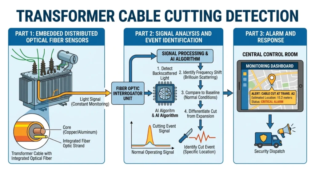
Figure 1. A supervised continuity loop around a distribution transformer, from the monitored conductors to the controller.
Secondary Cable and Grounding Wire Protection: What Each Line Tells You
Secondary cable and grounding wire protection are often treated as one item on a bill of materials, but the four cable families around a transformer fail in four different ways, and each one leaves a different signature at the detector, so the first design decision is to list which family you are protecting rather than which sensor you will buy. Treating them as interchangeable is the most common mistake in cable monitoring specifications.
| Cable family | Typical duty | What a cut looks like on site | Immediate consequence | Earliest detectable signal |
|---|---|---|---|---|
| Primary (MV) power cable | 6–35 kV feed to the unit, the usual first target of transformer cable cutting detection | Supply lost at the transformer | Load-side outage within one cycle | Loss of voltage and loss of current together |
| Secondary (LV) power cable | 400 V feed to the load | Unit may keep running on remaining phases | Metering and control lost while the unit still looks normal | Loss of metering current with supply unchanged |
| Grounding / earthing conductor | No continuous load current | No electrical change at all | Touch and fault protection removed | Continuity loss on the earth loop only |
| Monitoring and signal wiring | Low-voltage data and alarm path | The detector goes quiet | The site loses its own alarm channel | Loss of loop state or heartbeat |
The table is the heart of this page because the second and third rows are where programmes fail. A cut secondary cable does not stop a transformer from humming. The core still carries flux, the tank is still warm and the unit still looks healthy from the pole, so an inspector walking past sees nothing wrong, while the metering and protection circuits that would report a fault have already been isolated. The same is true of the grounding conductor. It carries no load current in normal operation, so cutting it produces no change in any meter reading, and the loss only shows up when a fault current has nowhere safe to go. IEC 60255-1:2022 defines the general requirements for measuring relays and protection equipment, which is the family that shares this secondary circuit, and it is the standard to quote when specifying what must remain functional after a section of that wiring is removed.
The grounding conductor deserves its own warning. It is frequently the first line a crew cuts, because earthing is what makes a unit safe to work on and to dismantle. Removing it before the work is a preparation step, not an accident. A programme that monitors only the power conductors will watch a unit being prepared for removal and see nothing unusual until the metering drops out. Earth continuity is covered by IEEE Std 80-2013, the guide for safety in AC substation grounding, which is the reference to cite when justifying a monitored earth loop to a utility engineer.
[PERSONAL EXPERIENCE] The pattern that repeats across loss records is not a dramatic attack. It is a quiet sequence of small cuts spread over days, each one removing a signal that nobody was watching, until the unit can be lifted with no alarm at all. The lines that go first are the ones the owner assumed were not worth monitoring.
Why Cable Cutting Is an Early Warning Sign of Transformer Theft
Cable cutting earns its place in a theft programme because it is the earliest step in the sequence that leaves a usable signal behind, and an alarm at the earliest step buys response time that any later alarm has already spent. A crew that intends to remove a unit has to isolate it first, and isolation means cutting, so the cut is the first irreversible act after the reconnaissance visit.
Transformer cable theft follows a stable order. A site is scouted, sometimes more than once. The cables are cut and stripped, often days ahead, because bare copper can be sold whether or not the transformer is ever taken. The enclosure is opened to disconnect what remains. Only then does a crane or a team with jacks arrive. Each step has a sensor that fits it, and the transformer tampering detection page walks the same sequence from the enclosure side, while the transformer anti-theft monitoring system page shows how the individual signals combine into one programme.
| Step in the loss sequence | Typical timing | Signal available | Value of catching it here |
|---|---|---|---|
| Scouting | Days ahead | None from the asset itself | Site logs and neighbours only |
| Cable cutting | Days ahead | Continuity and supply events | High: the cut is the first hard evidence |
| Enclosure opening | Minutes to hours before the lift | Tamper and door switches | Highest: the crew is still on site |
| Lifting | The loss itself | Tilt and movement | Recovery odds, not prevention |
An alarm at the first row is knowledge, not protection, because nobody is watching the site when a scout walks past. An alarm at the second row is the first row that a monitoring system can actually own, which is why cable continuity sits at the start of the chain rather than at the end. The distribution transformer theft page describes what the completed sequence costs, and the theft prevention guide covers the physical hardening that slows the later steps down.
How Does Cable Cutting Detection Work?
A cable cut detection sensor watches a supervised circuit that runs through the conductor or the terminal it is protecting, and the controller interprets any change in the state of that circuit as an event rather than as a reading, which is why the whole chain from sensor to notification can complete in seconds. Five links make up that chain.
- Baseline. A small supervisory current circulates through the loop at all times. The loop commonly closes through the monitored conductor or through a dedicated pilot wire, and it carries an end-of-line resistor so that the controller sees a known value, not just presence or absence.
- Interruption. When the loop opens, the supervisory current stops or the measured resistance jumps to the open-circuit value. The controller sees the transition, not the absolute value, which is what lets it react to a fractional-second cut.
- Evaluation. The controller compares the transition against a threshold and a time delay. A short delay rejects surge and contact bounce; a supervised loop with an end-of-line resistor separates a genuine open from a short-circuit bypass.
- Local output. A relay, a sounder or a beacon fires locally. This step matters on unmanned sites because a local output is the only signal that survives a failed communication link.
- Notification. The event is timestamped and sent over the site communication path, commonly using a telecontrol protocol such as the one described in the transformer theft detection overview, and it reaches whoever is on the response list.
The fifth link is the one that decides whether the system is worth its cost, because an event delivered to an inbox nobody watches is indistinguishable from no event at all. The design work that turns a detector into a programme is mostly administrative: who is called, in what order, and what happens when the first name does not answer.
What Cable Problems Can Be Detected?
A cable monitor detects the family of faults that change the electrical state of a conductor or a loop, which in practice covers complete cuts, clean separations, open circuits, damage to signal and security wiring, and partial damage that has not yet broken the conductor. It does not detect a problem that leaves the loop state intact, and stating that limit up front keeps the specification honest.
| Fault form | What the loop or meter sees | How reliably it is caught |
|---|---|---|
| Complete cut | Loop opens immediately | High; the transition is unambiguous |
| Cable disconnection at a terminal | Loop opens, sometimes intermittently | High, but wind and thermal movement can mask it |
| Open-circuit condition | Sustained open state | High; identical to a cut at the loop level |
| Damage to monitoring or security wiring | Loss of loop state or heartbeat | High; the detector reports its own blindness |
| Partial cable damage | Leakage, intermittent contact, no clean break | Moderate; needs insulation monitoring as well as continuity |
Partial damage is the row that defeats a continuity-only design. A cable that has been nicked but not severed keeps the loop closed, so a continuity monitor stays quiet until the conductor finally separates, which may be weeks later or during the next storm. Catching that case needs a second method, usually insulation monitoring or a periodic resistance test, and the specification should say so rather than implying that one loop covers everything.
The last row of the table is worth a sentence of its own. When the cut line is the wiring that feeds the monitoring system, the system loses the ability to report its own loss. That is why a supervised loop with a heartbeat, rather than a passive contact, is the honest choice for the signal path. A detector that can only speak while it is connected will fall silent at exactly the moment its silence is the message.
How to Reduce False Alarms in Cable Detection
False alarm reduction in cable detection starts from the recognition that most cable events are not thefts, and it works by separating the innocent causes from the hostile one before an alarm is allowed to escalate, rather than by making the detector less sensitive. Sensitivity cannot tell a planned cut from a hostile one, so the logic has to.
| Apparent event | What the detector sees | How to separate it |
|---|---|---|
| Planned maintenance | Loop deliberately opened | Bypass schedule and maintenance-window flag in the controller |
| Third-party construction | Cable struck, moved or re-routed | Duration and location correlation with the work permit |
| Lightning or switching surge | Brief transient on the loop | Short pickup delay, longer than the transient |
| Animal or weather damage | Gradual insulation failure | Insulation monitoring rather than continuity alone |
| Communication fault | No data reaches the operator | Heartbeat supervision, raised as a comms event, not a cable event |
Two rules carry most of the value. The first is that the loop should be supervised with an end-of-line resistor, so that a bypass reads differently from an open circuit. Without that distinction, a crew can short the loop in seconds and the transformer cable cutting detection controller reports a tidy, unremarkable “healthy” state. The second is that a cable event should be correlated with other signals before it escalates: a lost loop together with a loss of supply is a strong pattern, while a lost loop on a pole where a work permit is open is very likely routine. Correlation is cheap because the signals already exist, and it is the single most effective lever on the false-alarm rate. The vibration monitoring and tilt detection pages describe the companion signals that a correlation rule can draw on.
Cable Cutting Alarm Design: Sensors, Logic and Notification
A cable cutting alarm should be designed from the list of conductors that need protecting, not from a sensor catalogue, because the right sensing method follows from whether the conductor can carry a pilot loop and whether the load current may be interrupted. Four methods cover nearly every requirement, and each has a blind spot that belongs in the scope.
| Method | What it monitors | Best fit | Blind spot |
|---|---|---|---|
| Supervised continuity loop | State of a closed pilot loop | Cables that can be looped, and earth conductors | Conductors that cannot be looped, such as a live phase with no spare core |
| Earth-loop continuity | State of the grounding conductor | Earthing integrity, the line crews cut first | Needs a dedicated conductor run back to the controller |
| Voltage and current sensing | Live electrical quantities | Confirming loss of supply or loss of load | Cannot separate a cut from a planned outage on its own |
| Insulation monitoring | Leakage and insulation resistance | Partial damage before the conductor separates | Slow to respond to a clean cut, so it complements rather than replaces continuity |
The selection logic is short. If the conductor can carry a pilot loop, a supervised continuity loop is the most direct and the most sensitive method, because it reacts to the transition itself. If the conductor is a live supply that must be watched for outage as well as for cutting, pair voltage or current sensing with continuity so the two can be correlated. If partial damage is a known local pattern, add insulation monitoring, and accept that it is a slow second opinion rather than a fast alarm.
Notification is part of the design, not an afterthought. A local relay or beacon should fire on site whether or not the communication link is up, and the remote path should carry a timestamped event rather than a raw contact state. The response list, the escalation window and the definition of a cleared event all belong in the commissioning document, because those details decide whether the alarm reaches a person who can still do something about it.
Cable Cutting Detection for Remote Transformers
Cable cutting detection for remote transformers carries more weight than the same system does on a supervised site, because on a remote pole the cut is often the only event that anyone will ever know about before the unit is gone. Distance does not change the physics of continuity, but it changes what a missed alarm costs.
| Remote-site condition | Why it raises the risk | What detection changes |
|---|---|---|
| No staff on site | Nobody sees or hears the work | An alarm replaces the witness who is not there |
| Long inspection interval | Days pass between visits | The gap collapses from days to seconds |
| Exposed cable runs | Overhead LV and earthing within reach | Continuity supervision covers the whole run |
| Outage disguised as maintenance | Crime that looks like routine work | A timestamped event record separates the two |
The last row is specific to remote sites and is worth dwelling on. A crew that cuts the feed creates an outage that looks, from the control room, exactly like a fault or a planned disconnection. Without a monitored cable, the outage is filed as a fault and a line team is sent out to find a transformer that is no longer there. With transformer cable cutting detection in place, the same outage arrives with a cable event attached, and the response starts from a different premise. The economics are simple: on a site an inspector reaches in twenty minutes, detection is a convenience; on a site reached in two days, detection is the difference between a response and a recovery.
Combining Cable Detection With Other Sensors
Cable detection should not run alone, because it covers one step of a sequence and the strongest alarms come from two steps that agree, so the honest way to describe it is as the earliest link in a chain rather than a complete system. Each sensor owns a stage, and the stages are ordered by when the crew does the work.
| Signal source | Stage it covers | Where it is described |
|---|---|---|
| Cable continuity | The cut, before anything is opened | This page |
| Enclosure and tamper switches | Opening the cabinet or cover | The tampering detection page |
| Vibration burst | Impact, prying and drilling | The vibration monitoring page |
| Tilt | The lift itself | The tilt detection page |
| Loss of supply | Confirmation that the unit is isolated | The theft detection overview |
Two signals that arrive together carry far more weight than either alone. A lost earth loop followed within minutes by a lost supply is a pattern no planned maintenance visit produces, while a lost loop on a pole with no work permit is a warning worth a phone call. The design rule is to correlate rather than to duplicate: do not add a second sensor that measures the same thing, add one that measures the next step. Everything specific to vibration and tilt belongs to the pages linked above, where the sensor choice and threshold tuning for those signals are covered in full.
Limitations of Cable Cutting Detection
Cable cutting detection has hard limits, and writing those limits into the specification before any hardware is ordered is the fastest way to build a programme that survives its first year in the field and its first nuisance alarm that someone has to answer. A monitor that is oversold produces a fleet that operators stop trusting, which is worse than no monitor at all.
- It reports a circuit, not a person. A continuity event says that a conductor opened. It cannot say who opened it, or why. Evidence for any follow-up comes from cameras, site logs or the response team’s own observations.
- It only covers the loops that are wired. An unwired conductor is an unmonitored one. If the scheme watches the primary and the earth but not the secondary, a cut on the secondary produces silence, and that gap should be documented as a decision rather than discovered later.
- It competes with the outage it detects. Many cuts are accompanied by a loss of supply, so the controller and its backup battery have to ride through that outage to report the event. A design without adequate backup power can detect a cut and then lose the ability to tell anyone.
- It can be bypassed. An unsupervised loop can be shorted with a jumper, and the controller will report a healthy state. Supervised loops with end-of-line resistance close most of this gap, but they must be installed and maintained to keep working.
- It cannot separate a cut from a planned disconnection by itself. A work permit, a bypass schedule or a second correlated signal has to do that job, which is why the false-alarm logic is part of the system rather than an optional extra.
- It degrades where nobody looks. Corroded terminals, loose connectors and water ingress all erode the loop over time. The device that is never inspected never fails loudly, and a programme that skips its own maintenance quietly stops working before anyone notices.
The honest summary is that cable detection buys time, not certainty. It moves the operator’s first knowledge of an incident from after the lift to before it, and everything else, including the response itself, depends on what the operator does with those minutes.
| Limitation | Can design reduce it? | How |
|---|---|---|
| Reports a circuit, not a person | No | Add cameras or site logs for evidence |
| Only covers wired loops | Yes | Extend the loop schedule to every conductor that matters |
| Competes with the outage it detects | Yes | Battery backup and on-device event storage |
| Can be bypassed | Partly | Supervised loop with end-of-line resistance |
| Cannot separate a cut from planned work | Yes | Work-permit flag and correlation logic |
| Degrades without maintenance | Yes | Scheduled loop testing, not just installation |
Five of the six rows can be improved at design time, and only the first one is a permanent limit. That ratio is worth stating in any specification, because it turns a list of weaknesses into a list of decisions.
How Houfeng Delivers Cable Cutting Detection
Houfeng scopes cable cutting detection around the site list and the loss history rather than around a fixed product, because the right mix of continuity loops, earth monitoring and correlated signals differs with the conductors that need protecting on each pole. The delivery sequence below is the same one used for single units and for district-wide rollouts.
- Site survey. Each unit is walked and every conductor is listed, including the primary feed, the secondary feed, the grounding conductor and the signal wiring, with the openings crews actually use marked on the drawing.
- Loop schedule. Every monitored conductor is assigned to a supervised loop or an earth loop, and any conductor that is deliberately left unwatched is recorded with the reason.
- Detection logic. Thresholds, time delays and the correlation rules between cable events, supply events and communication heartbeats are set before commissioning, not tuned afterwards in the field.
- Local and remote outputs. A local relay or beacon is configured alongside the remote path, so an event survives a failed link and reaches the response list with a timestamp.
- Commissioning and handover. Each loop is tested by opening it deliberately, the escalation list is exercised with a live test alarm, and the drawings and the response procedure are handed over with the equipment.
The reference unit for the cable and enclosure signals is the transformer anti-theft monitoring device, which accepts continuity, earth and enclosure inputs on one controller so the correlation rules above can be applied without a separate gateway.
Frequently Asked Questions
What is transformer cable cutting detection? Transformer cable cutting detection is a monitoring method that watches the continuity of the cables serving a transformer, including the primary and secondary conductors, the grounding conductor and the signal wiring, and raises an event when any of those circuits changes state without authorisation. It reacts to the moment a conductor opens rather than to the outage that follows, which is what gives it its speed.
How does cable cut detection work? A supervised loop carries a small supervisory current through the monitored conductor or a pilot wire, with an end-of-line resistor so the controller sees a known value. When the loop opens, the current stops or the resistance jumps, and the controller treats the transition as an event. It then fires a local output and sends a timestamped message over the site communication path.
Can cable cutting detection detect transformer theft? It detects the cutting, which is usually the first hard step of a theft rather than the theft itself. That distinction is the point: an alarm at the cut arrives before the unit is moved, when a response is still possible, while an alarm at the lift only tells an operator that a transformer has already gone. Cable detection is an early-warning layer, not a verdict.
What types of cable problems can be detected? Complete cuts, cable separations, open circuits, damage to monitoring and security wiring, and partial damage that has not yet separated the conductor where insulation monitoring is added. A continuity-only loop catches everything except the last case, which is why partial damage is the fault that decides whether a second method is needed on a given site.
Can cable detection be used on remote transformers? It is most valuable there. A remote pole has no witness, a long inspection interval and exposed cable runs, so the cut is often the only event anyone will learn about before the unit is gone. A monitored cable turns an outage that would be filed as a routine fault into a timestamped cable event with a different response behind it.
Can a cable alarm be silenced or bypassed? An unsupervised loop can be shorted with a jumper, and the controller will read a healthy state. A supervised loop with end-of-line resistance separates a bypass from a genuine open, and heartbeat supervision catches the loss of the reporting path itself. Both details are cheap at design time and awkward to retrofit later.
How can false alarms be reduced in cable detection? By separating innocent causes from the hostile one before an alarm escalates, using a maintenance bypass schedule, a pickup delay longer than switching transients, correlation with loss-of-supply events and a distinct communication-fault channel. Sensitivity cannot tell a planned cut from a hostile one, so the logic has to do that work.
Conclusion and References
Transformer cable cutting detection does one narrow job very well: it reports that a conductor opened, in the seconds after it opened, so that the earliest step of a theft becomes visible while there is still time for the owner to act. The value is not in the sensor. It is in which conductors are wired, whether the loop is supervised, whether the event survives the outage, and whether the alarm reaches a person who is willing to answer the phone at three in the morning. Get those four decisions right and the cut becomes the first alarm rather than the last silence.
If you are scoping a district rather than a single pole, send us your requirement with the site list and the loss history for each area. An application engineer will return a conductor-by-conductor protection schedule and a supervised-loop drawing built around the transformer anti-theft monitoring device, and you can request a datasheet for the reference configuration first.
Sources
- IEC 60502-2:2014, Power cables with extruded insulation and their accessories for rated voltages from 1 kV up to 30 kV, Part 2: Cables for rated voltages from 6 kV up to 30 kV. IEC Webstore
- IEC 60255-1:2022, Measuring relays and protection equipment, Part 1: Common requirements. IEC Webstore
- IEEE Std 80-2013, IEEE Guide for Safety in AC Substation Grounding. IEEE Standards
Written by the engineering content team at Baoding Houfeng Trading Co., Ltd., which works with utilities, EPC contractors and industrial operators on transformer monitoring and protection projects. Technically reviewed by [Reviewer name], senior protection and metering engineer, [X] years in distribution network operations (to be confirmed by the client). Last updated: 4 October 2026.
[…] Cable Cutting Detection […]