

Rural transformer theft prevention is the design of a protection scheme around the shape of a network rather than around the equipment, because on a rural feeder the patrol interval, the travel time and the load profile are all set by distance, and a scheme that ignores that geometry will be correct on paper and late in the field.
The starting point is that a rural feeder is long and thin. Load centres are small and widely separated, so transformers sit every few hundred metres along a route that may run for tens of kilometres, and the utility’s presence along that route is periodic rather than continuous. That single fact rearranges the usual order of protection work. A guarded site is protected by adding layers to something that already has a boundary; a rural site has no boundary to strengthen, so the work moves to deciding which sites deserve instrumentation at all, and how long a message from one of them stays useful.
Two distinctions are worth fixing before the details. The installation form itself, and the removal methods that depend on it, are treated on the pole mounted installation page, while the controller that the field channels report into is described on the transformer anti-theft monitoring system hub. This page stays with the network: how far apart the assets are, how often anybody passes them, which parts of the feeder theft actually attacks, and what each protection layer can still deliver once distance is taken into account.
Key Takeaways
- A long patrol interval is arithmetic rather than neglect. The interval follows from asset count divided by crew capacity, so doubling patrol frequency doubles crew time while the marginal interception keeps falling.
- Rural theft risk clusters by accessibility rather than by asset value. The attacker’s first constraint is transport, so the units that matter are the ones a vehicle can reach, not the ones with the largest nameplate.
- Seasonal load swings undermine load-based detection. Irrigation-season current on the same unit can sit well above the off-season baseline, so a rule tuned in one season misfires in the other.
- The discovery clock is set by the settlement cycle rather than by the patrol. Meter reading and billing create a contact point more regular than any inspection round, and that is what really bounds how long a theft stays hidden.
- The thinnest layer on a rural feeder is response rather than physics. There is almost nothing to fence, while the journey to site can exceed any warning the equipment is able to give.
- Coverage gaps cannot be engineered away at every site. Where the network is absent, the honest configuration is local recording plus retrieval, not real-time reporting.
What Is Rural Transformer Theft Prevention?
Rural theft protection is a four-part arrangement in which physical measures slow a removal down, detection channels report that one is in progress, a reporting path carries the message out of the area, and a named responder acts on it, and on a rural feeder the last two parts are the ones that decide the result.
The familiar version of that list assumes a site with a fence, a mains supply and somebody who passes it daily. A rural distribution transformer has none of the three. There is usually no perimeter worth building, because the equipment sits on a pole or a small platform beside a field; there is no low-voltage auxiliary supply to run a cabinet from; and there is no routine presence, because the same crew that would inspect the site is also the crew restoring faults across the rest of the zone.
What remains is a set of measures that were designed for denser networks and now have to be re-priced against distance. Physical hardware still adds minutes to a removal, but minutes are only worth buying when somebody is coming, and on a rural feeder the arrival time is measured in hours. Detection still works, but its thresholds have to be derived from a site with seasonal load and unshielded wind exposure rather than from a substation bay. Reporting still works, but only where coverage exists, and the coverage map of a rural feeder has holes in it. Response is the layer that everything else is really sized against.
| Layer | What it assumes about the site | What a rural feeder actually offers | Where the layer lands in practice |
|---|---|---|---|
| Physical measures | A perimeter, a gate or an enclosure to harden | Open ground, a pole, sometimes a small platform | Minutes added to a removal, no signal generated |
| Detection | A stable baseline to compare against | Seasonal load, wind, farm machinery | Channels work, but every threshold needs a site record |
| Reporting | Continuous coverage at the site | Coverage with gaps along the route | Two site classes: reporting and recording |
| Response | A crew within the warning window | Journey times that often exceed the window | The layer that sets what the equipment is worth |
The choice between protection principles rather than rural-specific measures is compared on the prevent transformer theft overview, which is the right starting point when the question is which family of measures to buy. This page answers the narrower question that follows: once the network has been described honestly, which sites get which configuration, and what has to be measured before that can be decided.
Why Rural Transformers Are Vulnerable to Theft
Rural distribution transformers are exposed because three structural features of the network work together: assets are spread thinly along long feeders, there is no continuous human presence anywhere on the route, and the inspection interval is the arithmetic result of asset count divided by crew capacity rather than a security decision.
The first feature is dispersion. A rural feeder serving villages and irrigation pumps carries two to six transformers per kilometre of route, and the route itself runs for tens of kilometres. Two consequences follow immediately. The cost of any per-site measure is spread over very few units of revenue, so the same hardware that is a rounding error on an urban network becomes a visible line item here. And the exposure is not proportional to the number of transformers but to the length of the route that has to be watched, which is a much larger number.
The second feature is the absence of presence. This is not a staffing failure that a better roster would fix. A rural zone is defined by the fact that the load is far from the substation, and a crew stationed in the zone would spend most of its day travelling inside the zone rather than working. The patrol therefore covers the route rather than the asset, and the asset spends almost all of its life unobserved.
The third feature is the interval itself. If a zone holds a few thousand transformers and a crew can physically visit a limited number of sites per working day, the interval that results is a division problem, not a policy. A zone with 1,800 transformers, two crews and eight sites per crew-day produces an interval of about 112 working days, which is roughly five months between visits to any one unit, and adding a third crew only brings that down to about 75 days. Doubling the frequency again doubles crew time for a smaller gain than the first pass delivered, because the first pass already covers the sites that are easiest to reach and most likely to be attacked. Reaching a two-week interval on the same zone would need 23 crews doing nothing else, which is why the interval should be treated as a constant of the network and the discovery function moved elsewhere.
| Structural feature | Why it cannot be fixed by effort alone | What it forces into the design |
|---|---|---|
| Assets spread along a long route | Cost per protected site rises as site density falls | Tiered configuration instead of uniform configuration |
| No continuous human presence | A crew inside a large zone spends its day travelling | Detection that reports without a witness |
| Interval set by asset count and crew capacity | Frequency scales linearly, benefit does not | Discovery moved to the monitoring layer |
| Load profile with a strong seasonal swing | Irrigation load changes the baseline by season | Per-season thresholds or a wider alarm band |
The consequences of a theft on this kind of network are correspondingly stretched, and the transformer theft detection overview describes the sensing side of the answer. Procurement, transport, lifting and commissioning of a replacement unit all take longer at the end of a long route, the outage affects fewer customers but lasts considerably longer per customer, and emergency work is scheduled outside the normal round. That combination is what a rural transformer theft prevention programme is really buying down, and it is why the two numbers that follow matter more than the equipment list.
_Figure 1 shows a rural distribution transformer at the end of a long feeder route, with no perimeter, no auxiliary supply and no routine presence._
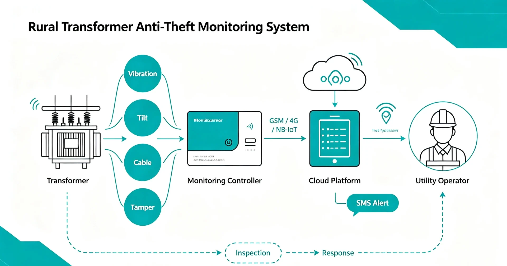
Power Supply Radius and Patrol Frequency Set the Design
Two numbers decide most of a rural protection design before any equipment is chosen: the supply radius that a feeder covers, and the patrol frequency the utility can sustain over that radius, and both are fixed by the network rather than by the security budget.
The supply radius is the distance a feeder is allowed to run from its source, and it is chosen by the planning department for voltage drop, losses and service quality. From a security viewpoint it does three things. It sets the length of route that has to be covered, it sets how far a responder has to travel from wherever the response is based, and it determines whether a radio or cellular path reaches the sites at the far end. A feeder planned around a 15 km radius produces a compact problem; the same asset count spread over 40 km produces a set of problems that are individually cheap and collectively expensive.
Patrol frequency is derived rather than chosen. The relationship is close to linear and blunt: interval equals the number of assets in the zone divided by the number of sites a crew can visit in a working day, multiplied by the number of crews. Because the numerator is large and the denominator is small, the interval that emerges is measured in weeks or months, and it does not move much when the security department asks for it to. What does move is the cost: an extra pass over a 30 km route consumes the same crew-days that a fault restoration or a connection job would have used.
The two numbers combine into the first design rule on this page. If the interval cannot be shortened to the timescale of a theft, then the interval must be treated as a constant and the discovery function has to be transferred almost entirely to the monitoring layer. That is not an argument for monitoring everywhere, because the same geometry that rules out patrols also rules out uniform instrumentation. It is an argument for measuring both numbers before specifying anything, and for budgeting in messages rather than in sites.
[UNIQUE INSIGHT] The arithmetic also explains why patrol-based programmes plateau. Each additional pass over a long route costs the same crew-days as the previous one, while the sites it newly covers are the ones further from the road and therefore less likely to be attacked. The marginal value of the sixth pass is a fraction of the first, and the same crew-days spent on a band A installation buy a detection that works every night of the year rather than once a month.
| Patrol planning variable | Typical situation on a rural feeder | Effect on the protection design |
|---|---|---|
| Assets in the zone | A few hundred to a few thousand units | Determines the interval, not the security level |
| Sites a crew can visit per day | Limited by travel between sites rather than by work | Interval scales almost linearly with asset count |
| Supply radius of the feeder | Long enough to reach distant villages and pumps | Sets both the route length and the coverage questions |
| Season | Irrigation season against the off-season | Changes both the load baseline and the number of people near the equipment |
Where the coverage question is settled, the remaining decision is the reporting path, and the trade between cellular options along a long route is set out on the remote monitoring communication page. What belongs here is the arithmetic above it: a reporting interval that is longer than the journey a crew has to make changes nothing, so the journey is measured first and the interval is chosen after. That single ordering removes most of the reporting configurations that look reasonable on a product sheet and are useless on a rural feeder, and it is the cheapest correction available to a programme planned in the other order, because the most common failure in rural transformer theft prevention is not a missing channel but an interval chosen before anyone measured the journey.
Where Theft Risk Sits Along a Rural Feeder
Theft risk on a rural feeder is not spread evenly and it does not follow asset value: it follows accessibility, because the first constraint on any removal is moving the unit away from the pole, which means the sites that matter are the ones a vehicle can reach.
The reasoning is transport arithmetic rather than criminology. A small single-phase unit of the kind common at the far end of a rural route can be taken down and carried to a track by three people with hand tools and a handcart, and at 10 to 50 kVA it weighs little enough for that to be practical. A three-phase unit of a few hundred kVA requires a truck with a crane or a winch, straps and a driver, and it needs somewhere to park that vehicle close enough for the lifting to reach. Everything else being equal, the second operation is larger and noisier, and it is therefore the one that a network can actually plan around, because it has visible prerequisites.
Those prerequisites are what makes the risk map predictable. Sites next to a farm track, at the end of a village road, beside an irrigation pump house or within a short carry of a field boundary are the ones where the full operation is physically possible. Sites that need a 200 m carry through soft ground are not impossible to attack, but they need more people, more time and a plan, and the equipment recovered has to be moved the same distance out. In practice the distribution of incidents concentrates on the first group while the asset register treats both groups as equivalent rows in a spreadsheet.
The same logic explains a counter-intuitive pattern that field teams report repeatedly: the unit that is stolen is often not the largest one on the feeder. The largest units are frequently installed in places chosen for electrical reasons rather than for ease of access, and a 100 kVA unit beside a road is a better target than a 500 kVA unit at the end of a rough track. A programme that ranks assets by kVA therefore protects the wrong sites, and it also spends its budget on the units that are least likely to be attacked first.
| Accessibility band | Typical position | Transport needed for a removal | Suggested configuration |
|---|---|---|---|
| A: vehicle within a few metres | Farm track, village road end, pump house | Truck with crane, straps, several people | Full channel set, shortest reporting interval, local alarm |
| B: short manual carry | Field boundary, footpath crossing | Hand tools, handcart, small team | Movement and tamper channels, standard interval |
| C: no practical carry | Mid-field, soft ground, no track | Effort exceeds the value of the unit | Inspection and hardware measures, recorded on the asset file |
| A combined with a recent incident | Any band that carries a local theft history | Same as the band, with local knowledge | The highest rural transformer theft prevention priority on the feeder |
The removal itself, and the sequence of signals it produces, depend on the mounting form rather than on the network, and that material belongs to the pole mounted transformer theft analysis. What the network contributes is the ranking: a feeder can carry a programme built to protect rural distribution transformers from theft with a modest channel inventory, as long as the inventory is placed by accessibility band rather than by nameplate rating.
Rural Transformer Security: What Each Layer Can and Cannot Deliver
Rural transformer security is normally described as four layers, and on a rural feeder each of the four loses something in the translation from a guarded site, so it is worth stating what every layer can still deliver before a budget is written around the list.
The physical layer survives only in a reduced form. With no perimeter to harden, the available measures are the ones that travel with the equipment: hardened fastenings, shielded or caged terminals, anti-removal hardware, and locks on covers and cubicles where a cubicle exists. Each adds time, and none of them produces information. On a rural feeder the layer is worth having mainly because it raises the minimum effort a removal costs, which shifts a marginal attack to a different site rather than preventing it outright.
The detection layer is the one that changes most in character. At a guarded site a detection channel can be tuned against a quiet background; on a rural feeder the background is seasonal load, wind on an unshielded structure, farm machinery passing within metres, and irrigation pumps switching in and out. Most of these transformers sit on an 11 kV or 33 kV feeder with a low-voltage side around 400 V, and the sensing equipment has to work outdoors across a temperature span that can run from -25 °C on a winter night to 55 °C in the open on a summer afternoon. Every threshold therefore has to be derived from the site’s own record, and the equipment that has to hold those settings outdoors belongs to an environmental class chosen for exposed locations rather than for a shelter.
The reporting layer depends on something the utility does not control. The cellular coverage along a rural route is a commercial question as much as a technical one, and the sites at the far end of a long feeder are exactly the ones where the question is least likely to have a comfortable answer. The response layer is the one that distance attacks directly, and it is the layer that determines whether the other three were worth buying.
| Layer | What it delivers on a rural feeder | Failure mode when it carries the whole job |
|---|---|---|
| Physical measures | Time, measured in minutes added per removal | Longer theft, same outcome, no information produced |
| Local alarm | Deterrence with no witness to hear it | Sound in an empty field, no record for the control room |
| Detection channels | An event record and a message while the removal is in progress | Detection without dispatch becomes documentation |
| Reporting path | The message reaching a person somewhere else | Coverage gaps leave a subset of sites reporting nothing |
| Response procedure | The only layer that can end a removal | The layer the network’s geography constrains hardest |
The honest summary of rural transformer security planning is that three of the four layers can be specified and one of them has to be lived with. Seen from the network side rather than the equipment side, rural power network transformer protection is mostly a question of deciding which sites to instrument and how much time each of them is worth, and only then of choosing what to install. That is why the next two sections deal with what monitoring can and cannot change, and with what the discovery timeline actually looks like when nobody is watching the site.
Remote Monitoring for Rural Transformers: What It Changes
Remote monitoring for rural transformers changes one variable and leaves the rest alone: it moves the moment of discovery from the next contact to the moment of the event, which is worth having but does not shorten a journey or widen a coverage gap.
What it changes is substantial in one respect. On an unmonitored feeder the time between a theft and the utility’s first knowledge of it is set by the next routine contact, which may be 60 days away or more. With monitoring, that interval collapses to the reporting interval of the device, and for the first time the utility is dealing with an event that is hours old rather than weeks old. Recovery rates, the chance of finding equipment still on site, and the possibility of matching a record to a vehicle movement elsewhere on the feeder all depend on that single change, and the difference between a 1-hour report and a 24-hour heartbeat is the difference between a dispatch and an entry in a log.
What it cannot change is the geography. The journey from the crew’s base to a site at the end of a long route takes what it takes, and no reporting interval shortens it. If the journey is longer than the removal, the monitoring system is not a prevention measure for that site; it is an evidence and recovery measure, and describing it as prevention distorts the budget decision that follows. The same applies to coverage: where there is no usable network, the device can record and be read on the next visit, but it cannot report at the moment of the event, and pretending otherwise moves the disappointment to the first incident.
One further point belongs to the network rather than the device. Monitoring on a rural feeder is normally bought in quantity, and the value of the purchase depends on the platform behaviour at scale, where the question stops being which channels a single site has and becomes how alerts from hundreds of sites are triaged. The comparison between cellular options along a long route, and the wider questions of protocol and coverage, are set out on the remote monitoring communication page, which is the companion to this one for any programme that has to choose a reporting path for sites at the far end of a feeder. The deployment pattern for sites with no permanent staff is described on the transformer theft monitoring page, which is the companion to this one whenever a rural feeder contains long stretches with nobody nearby.
| What monitoring changes | What it does not change |
|---|---|
| Time from event to first knowledge | Travel time from base to the affected site |
| Availability of a dated event record | Whether coverage exists at the far end of the feeder |
| Ability to correlate a site with the load pattern | The number of sites a crew can physically protect |
| Chance of recovering the unit or the evidence | The cost of a replacement at a remote location |
Reading a Late Detection: What the Settlement Cycle Tells You
On a rural feeder the discovery of a theft is bounded by the next contact a customer has with the network, and that contact is usually a meter read, a bill or the start of an irrigation season rather than an inspection round, which is why the event record matters more here than the live alarm.
The insight is simple once stated. A rural network has a contact rhythm that is more regular than any inspection: reading meters, issuing bills, collecting payment, and starting or stopping pumps at the beginning and end of a season. Those contacts happen in the same place at predictable times of year, and each of them is an opportunity for a customer to notice that something is wrong. The practical effect is that a theft on an unmonitored part of the feeder is typically discovered not when the equipment is taken but when a user turns something on and nothing happens.
For the design this sets three requirements. The first is the retention length of the event record. If the natural discovery delay is measured in weeks, an event log that keeps only the most recent few hundred entries will have overwritten the relevant message by the time anyone asks for it. Retention should be sized against the contact cycle the site actually has, not against the reporting cycle the device happens to use.
The second is the value of local evidence. The first witness on a rural feeder is usually a customer, a pump operator or a meter reader rather than a trained inspector, so anything that leaves a visible trace at the site carries more weight here than it would at a substation. Cable seals, tamper indicators, paint marks broken by a lifted cover and a local alarm all help a non-specialist report something useful.
The third is the shape of the alarm platform. A theft on a rural feeder frequently arrives disguised as a supply complaint, which means the operator has to be able to move in both directions: from a complaint to any recorded event at the same distribution substation in the preceding period, and from an event to the customers who depend on that site. A platform that only raises real-time alarms, without a searchable history by feeder and date, throws away the correlation that makes the record worth keeping.
[UNIQUE INSIGHT] The consequence is that on a rural feeder the event record is a more valuable asset than the alarm, and it is usually the one specified last. An alarm that fires when nobody is on shift produces a notification, while a searchable history that survives to the end of the quarter produces a pattern, and the pattern is what turns a supply complaint into a located theft with a date attached to it.
| Discovery path | Typical delay after the event | What the design has to provide |
|---|---|---|
| Remote event reported at the moment it occurs | Minutes to hours | A named responder and a triage rule at the platform |
| Event recorded but not transmitted until later | Hours to days | Local storage sized against the coverage gap |
| Noticed during a meter read or billing contact | Weeks | Event history retained well beyond the reporting cycle |
| Noticed when a customer tries to use the supply | Weeks to months, season dependent | A complaint-to-event search by feeder and date |
| Noticed during a routine patrol | Weeks or months | Nothing, and the reason the previous four exist |
_Figure 2 shows the reporting and recording paths available at a rural site, from the sensing point to a control room that may be a long way from the feeder._
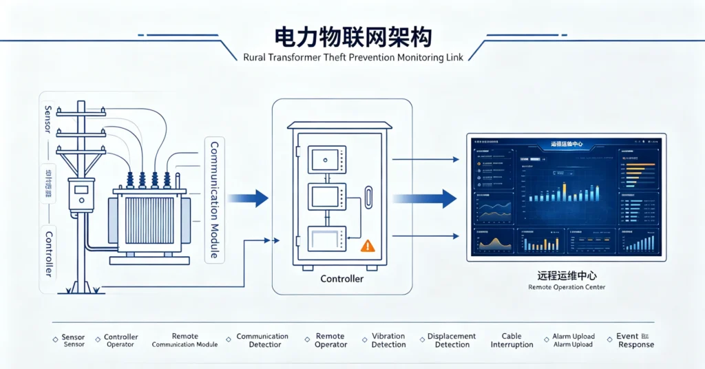
What Events a Rural Anti-Theft System Should Detect
A rural anti-theft system should detect six events, and the order in which they are listed is a response order rather than a priority order, because each event leaves a different amount of time before the equipment or the evidence is gone.
The list is shorter than the list of quantities that could be measured at a rural site, and that is deliberate. At a site with no routine presence, every additional channel adds a false-alarm surface without adding a response capability, and the channel that matters most is the one that fires furthest ahead of the removal. Movement of the structure and interference with covers come first for that reason, conductor continuity and phase state come next, and load-profile departures come last because they are the slowest and the least specific.
Thresholds are where the rural setting changes the equipment settings rather than the equipment choice. Movement channels have to be tuned above the site’s own wind-driven variation, which on an unshielded rural structure is larger than on a built-up site. Equipment installed outdoors without shelter should be specified against an environmental class written for exposed non-weatherprotected locations, so that temperature range, humidity, rain and wind are selected deliberately rather than inherited from an indoor product. Continuity channels have to tolerate the legitimate openings that rural work produces, from irrigation pump isolation to seasonal disconnection of a service.
| Event | Usable signal | Response the event justifies |
|---|---|---|
| Structure moved or unit lifted | Movement channel against the site’s recorded baseline | Immediate dispatch; this precedes a whole-unit removal |
| Cover or cubicle opened | Tamper and lid contact | Immediate dispatch; this precedes an in-place removal |
| Conductor continuity interrupted | Continuity loop on the secondary or the earth path | Investigate within the shift; a repair stop rather than a theft response |
| Single phase lost with the others healthy | Phase presence and current balance | Correlate with the fault log before dispatch |
| Monitoring unit removed or silent | Heartbeat expiry and unit tamper | Treat as an intrusion until proven otherwise |
| Load profile departs from expectation | Current and temperature against the seasonal baseline | Schedule an inspection; weak alone, useful with another channel |
The division of labour here is worth stating plainly. How a movement channel separates a removal from a passing tractor belongs to the transformer vibration monitoring page, how an attitude threshold is derived from a wind baseline belongs to the transformer tilt detection page, and how a continuity loop avoids alarming on a service that was legitimately isolated belongs to the transformer cable cutting detection page. What belongs to this page is the rural setting that changes all three: the size of the wind baseline, the seasonal shape of the load, and the frequency with which rural work legitimately interrupts a monitored circuit.
A Rural Transformer Theft Prevention Checklist
A rural transformer theft prevention checklist that works on a real feeder has six steps, and they run in one direction only: accessibility first, coverage second, thresholds third, and only then the equipment list, because every earlier step changes what the later steps should be.
The order matters because the steps are not independent. A coverage survey changes which sites can report, which changes how many sites a given budget can instrument, which changes the accessibility ranking that decides where the instruments go. A programme that starts with the equipment list fixes all of those answers before it has any of the information, and then spends its remaining budget explaining why some sites are silent.
The checklist also has to survive contact with a spreadsheet. A rural asset register usually records capacity, phase, location and installation date, and rarely records whether a truck can get within a few metres of the pole. That one missing field is the field that decides the risk ranking, so the first delivery in any rural programme is a survey that fills it in for the feeder in question rather than for the zone as a whole.
| Step | What is measured or decided | Output |
|---|---|---|
| 1. Accessibility survey | Vehicle access, carry distance and approach for every site | Each asset assigned to band A, B or C |
| 2. Coverage survey | Signal quality measured at the site, not at the office | Sites split into reporting and recording classes |
| 3. Threshold baseline | Wind variation and seasonal load recorded on site | A dead band per site rather than per project |
| 4. Band configuration | Channel set matched to the accessibility band | A channel list, with the sequence each channel covers |
| 5. Record design | Retention length and search keys for the event history | A 90-day store searchable by feeder and date |
| 6. Response drill | Measured arrival time for the worst route in the zone | A named owner and an escalation list per band |
Two of those steps deserve more weight than the rest. The coverage survey is the one most often skipped, and skipping it produces the most expensive kind of surprise, because a site that was assumed to be reporting turns out to be recording and the gap is only discovered after an incident. The response drill is the one most often treated as paperwork, and it is the step that decides whether wide area distribution network monitoring across a whole zone produces fewer thefts or a better archive of them.
The two survey results combine into a small matrix, and the matrix is what the equipment list is finally written from. A band A site with coverage takes the fullest configuration; a band A site without coverage takes the same sensing with a longer reporting cycle and a larger record; a band C site takes hardware and a place in the inspection round. Any other combination is a decision to spend money where a removal is not practical.
| Accessibility band | Coverage available at the site | Configuration the combination justifies |
|---|---|---|
| A | Reporting class | Full channel set, shortest interval, local alarm, immediate dispatch |
| A | Recording class | Same sensing, larger local record, retrieval on the next visit |
| B | Reporting class | Movement and tamper channels, standard interval, shift response |
| B | Recording class | Movement channel with a long record, hardware measures, scheduled review |
| C | Either | Hardware measures and an entry in the inspection round, no instrumentation |
_Figure 3 shows the survey sequence in the order it has to be carried out, from the accessibility band through coverage and thresholds to the configured site._
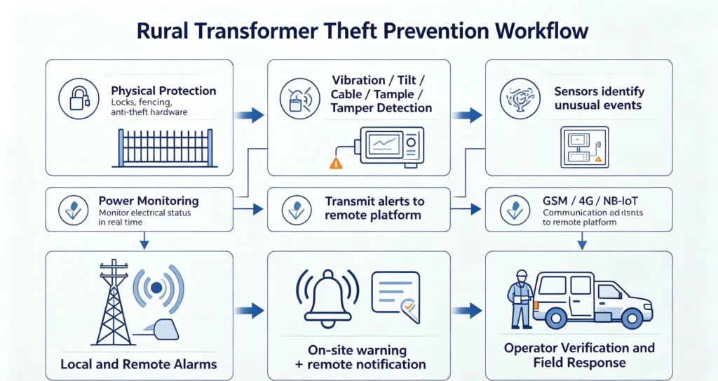
Limitations and Boundaries: What a Rural Feeder Cannot Deliver
Rural transformer theft prevention has hard limits, and each of them is a case where a correctly specified and correctly installed system will still fail to prevent a theft, so they are better planned for than discovered.
- It cannot close a coverage gap with equipment alone. Where the network is absent, the device records and is read later, so the site is outside real-time protection however well it is specified, and the only honest options are a repeater where one is economic, a different path where one exists, or classification as a recording site.
- It cannot separate a theft from an ordinary outage at a site that fails often. Where a feeder trips regularly, the prior probability of a genuine power loss is high, so a loss-of-supply event carries little information on its own and must be combined with a physical channel to mean anything.
- It cannot keep a load-based rule accurate across seasons. Irrigation load moves the current baseline far above the off-season figure, so a threshold set in one season either alarms through the other or is widened until it detects nothing.
- It cannot deliver a warning longer than the journey. On a feeder where the arrival time exceeds the removal time, the correct description of the system is detection and recovery, and a programme sold as prevention will be judged against an outcome it was never able to produce.
- It cannot rank risk without survey data. Accessibility banding depends on a field that most asset registers do not hold, and a banding exercise carried out from a map alone degrades quietly into ranking by capacity.
- It cannot protect every asset at the same level for the same money. Band-based configuration leaves the assets outside the highest band with a lighter channel set, which moves risk within the feeder rather than removing it, and that trade should be stated to the people who will report on the outcome.
| Limitation | Practical mitigation | Residual risk after mitigation |
|---|---|---|
| Coverage gap at remote sites | Repeater, alternate path, or explicit recording classification | A recording site stays invisible until retrieved |
| Frequent genuine outages | Require a physical channel alongside the electrical one | A theft inside a real outage window still hides |
| Seasonal load baseline | Per-season thresholds, or a band wide enough for both | Slow siphoning inside the band remains invisible |
| Journey longer than the removal | Position the site as detection and recovery | Deterrence is not delivered at that site |
| Register without access data | Field survey before banding, feeder by feeder | Sites omitted from the survey stay unranked |
| Band-based configuration | State the trade, review bands annually | Assets outside the top band carry more risk |
How Houfeng Supports Rural Distribution Programmes
Houfeng supports rural distribution programmes by measuring the network before specifying equipment, because the two most expensive mistakes on a rural feeder are a threshold copied from an urban project and a channel set sized for a site count rather than for a risk band.
The order that works is to survey first and specify second. Fill in vehicle access for every site on the feeder, record the signal quality measured at the site rather than estimated from a map, log the wind variation at the exposed positions over a full weather cycle, and measure the arrival time for the worst route in the zone. Those four measurements settle the banding, the channel set, the thresholds and the retention length, and they cost field time rather than equipment budget. A programme that begins with them usually finds that a smaller inventory than planned covers the highest-risk band completely.
| Delivery step | Measurement it depends on | Deliverable produced |
|---|---|---|
| Feeder survey | Vehicle access and carry distance per site | An accessibility band per asset, in one format |
| Coverage assessment | Signal quality recorded at the site | A reporting or recording classification per site |
| Threshold study | Wind and seasonal load records from the site | A dead band per site, valid for both seasons |
| Channel selection | Band and the plausible removal method | A channel list with the sequence each channel covers |
| Record and retention design | The contact cycle the site actually has | A retention figure and a search index by feeder |
| Response plan and drill | Measured arrival time for the worst route | A named owner and an escalation list |
For a first step, request a datasheet for the reference configuration and compare its channel set, autonomy and record retention against the survey figures above, or send us your requirement with the feeder data instead: the number of assets, the accessibility bands you can already fill in, the coverage class of the remote sites and the measured arrival time for the worst route, and an application engineer will return a band-by-band configuration, a threshold basis for each movement channel and a retention calculation. The device itself, including the tamper and heartbeat behaviour that a site without a routine presence depends on, is specified on the transformer anti-theft monitoring device page.
Frequently Asked Questions
Why are rural transformers vulnerable to theft? Three network features combine: assets are spread thinly along long feeders so unit protection costs more, there is no continuous human presence because a crew inside a large zone spends its day travelling, and the inspection interval is the result of asset count divided by crew capacity rather than a security policy. None of the three is a management failure, which is why the answer is a rural transformer theft prevention design rather than a patrol order.
How can rural distribution transformers be protected from theft? By ranking the assets first. Survey vehicle access for every site, band them by how easily a unit could be carried away, then give the highest band the fullest channel set and the shortest reporting interval, and the lower bands lighter configurations or hardware measures. A programme that protects rural distribution transformers from theft by instrumenting every site equally spends most of its budget outside the highest-risk group.
How does anti-theft monitoring work in a rural network? A movement or tamper channel detects interference at the site, the controller turns it into a dated event, and a cellular path carries the message to a platform where it is triaged against the other sites on the feeder. Where coverage is absent, the same event is stored and retrieved later. The sensing principle does not change with the network; the thresholds, the coverage class and the response procedure do.
Will irrigation-season load swings cause false alarms? They will if a load-based rule is tuned in the off-season and left in place. Irrigation current on the same transformer can sit far above the winter baseline, so the choice is between per-season thresholds and a band wide enough for both. The second option is simpler to operate and misses slow siphoning, so most programmes combine it with a physical channel that does not depend on load.
What can be done at a site with no usable cellular coverage? Three options, in order of cost: a repeater or an alternate path where either is economic, a store-and-forward configuration with local storage sized against the gap, or classification as a recording site visited on the normal round. The one thing that cannot be done is to report in real time, so the site should be documented as out of real-time coverage rather than quietly assumed to be covered.
Does physical protection remove the need for monitoring? No. Hardware measures add minutes to a removal and produce no information, so on a rural feeder with no perimeter to defend they change how long a theft takes rather than whether it succeeds. Monitoring is what tells the utility that the minutes were being spent, and the two layers are sized against the same journey: how long it takes a crew to arrive.
Conclusion and References
Rural transformer theft prevention is a design exercise in network geometry rather than a shopping list of devices, and the geometry fixes the two numbers that matter before any specification is written: how far the feeder reaches, and how often anybody passes along it. Everything else follows from those, including which sites are worth instrumenting, which thresholds are usable outdoors, and what a realistic outcome looks like at a site where the journey is longer than the removal.
The order that works is to survey access before choosing equipment, to measure coverage at the site rather than at the office, to derive movement thresholds from the site’s own wind record, to size the event record against the contact cycle rather than the reporting cycle, and to name the person who acts on a message from band A. A programme built in that order protects fewer sites than a uniform roll-out on the same budget and protects the right ones, and it can be defended both at the budget review and at the moment a tamper channel fires on a feeder where nobody is watching.
Sources
- IEEE 1366-2022, IEEE Guide for Electric Power Distribution Reliability Indices. IEEE Xplore
- IEC 60721-3-4:2019, Classification of environmental conditions — Part 3-4: Classification of groups of environmental parameters and their severities — Stationary use at non-weatherprotected locations. IEC Webstore
- IEEE C57.12.20-2023, IEEE Standard for Overhead-Type Distribution Transformers 500 kVA and Smaller; High Voltage, 34 500 V and Below; Low Voltage, 7970/13 800Y V and Below. IEEE Xplore
Written by the engineering content team at Baoding Houfeng Trading Co., Ltd., which works with utilities, EPC contractors and distribution operators on transformer monitoring and protection projects. Technically reviewed by [Reviewer name], senior distribution protection engineer, [X] years in rural network operations (to be confirmed by the client). Last updated: 4 October 2026.