

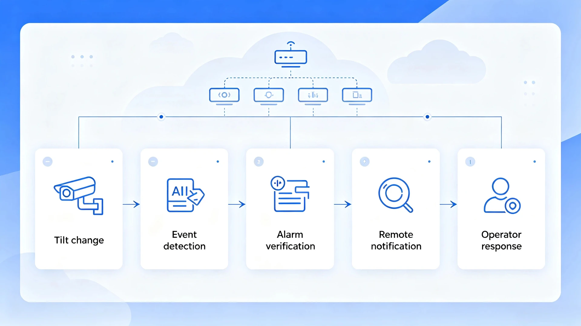
Transformer tilt detection is the practice of measuring the attitude of a unit against a reference position recorded while the site was undisturbed, and raising an event when that attitude changes by more than a threshold in less time than settlement or weather could explain. It watches the first mechanical consequence of a removal attempt.
Key Takeaways
- Attitude, not force, is what gets measured. A jack, a bar and a lifting sling all leave the same trace on this signal: the unit stops being level, and the angle at which it stops being level is the evidence.
- An angle on its own means nothing. Two degrees reached over three months is settling ground; two degrees reached in two minutes is a crew. Every threshold in this discipline is a pair of numbers, an angle and the time it took to arrive.
- The method covers one short window that no other signal covers well: the interval between the unit leaving its mounting and the unit being loaded onto a vehicle.
- Displacement and lifting are separate measurements that this page also owns. Displacement is translation without rotation, lifting is the jacking and slinging phases, and both need their own rules.
- The blind spot is structural. A crew that takes the entire mounting with the unit produces no relative angle at all, which is why a tilt programme is always paired with continuity and vibration sensing.
What Is Transformer Tilt Detection?
Transformer tilt detection is a monitoring method that treats the attitude of a transformer as a live measurement, compares it with a reference position captured when the site was known to be undisturbed, and reports a change that is too large or too fast to be explained by settling ground or shifting weather. It is a measurement of posture, not of force.
That distinction separates it from the signal-based methods it is usually deployed with. A vibration or continuity channel answers the question “did something happen?”, and it answers it well, but it cannot say what the unit is doing now. An attitude channel answers a narrower and, at the critical moment, more useful question: is the machine still sitting the way it was installed? A transformer that has been levered a few degrees off its plinth has already been entered into a removal sequence, and unlike an impact, that state persists. The operator is not reading a momentary spike; they are reading a condition that stays true until somebody corrects it.
The reason the method earns its place is timing. Most of the signals in an anti-theft system report an event in the past tense, and the response is forensic: the unit has been cut loose, the unit has been struck, the unit has been opened. Attitude is one of the few channels that can report a state still in progress, because the attitude only changes when the unit is actually being moved and stays changed once it has been. That is what makes the few minutes between a jack slipping under a base and a winch taking up slack worth engineering for, and the transformer anti-theft monitoring system page shows where that signal sits among the others on the same unit.
Three physical causes produce a tilt, and separating them is the whole of the design work. Ground and foundation movement is slow, is usually directional over weeks, and continues whether or not anybody is on site. Structural or mounting failure is sudden but happens without tools and without a visitor, and it tends to occur after weather rather than during it. Deliberate movement is the third and is characterised by speed and by correlation with other channels: it happens in minutes, in an ordered sequence, and alongside an impact or a continuity change.
| Cause | Rate of change | Direction | Correlated signals |
|---|---|---|---|
| Settlement and frost heave | Millimetres per month | Often consistent, seasonal | None |
| Structural or fixing failure | Sudden, one-off, no tools | Follows the failing member | None, but load and weather precede it |
| Deliberate movement | Degrees per minute | Toward the force applied | Impact, continuity break, enclosure switch |
The table is the reason a threshold cannot be a single number. Two of the three causes produce an angle, and only one of them is a threat. Separating them requires a second dimension, which is where the next section begins.
Transformer Tilt Detection Threshold: What Angle Indicates Tampering
A transformer tilt detection threshold is never a single angle, because the number that matters is always a pair: an angle and the time window over which that angle is allowed to accumulate before the change is treated as deliberate rather than as settling ground. A working starting point for a pole-mounted unit puts the early warning at about half a degree sustained for a minute, the main alarm at one to two degrees within a minute, and an immediate event at any change beyond five degrees, however long it took.
| Angle change | Time window | Most likely cause | Recommended action |
|---|---|---|---|
| Under 0.5° | Weeks | Settlement, thermal movement of the bracket | Log only, review at the quarterly inspection |
| 0.5° to 1° | Under 60 seconds | Early levering, or a loose fixing | Early warning, request a site check in the next visit |
| 1° to 2° | Under 60 seconds | A bar under one corner, a jack taking load | Main alarm, dispatch or remote confirmation |
| 2° to 5° | Under 10 seconds | The unit has been lifted clear of its support | Immediate alarm, treat as theft in progress |
| Over 5° | Any | The unit has left its mounting | Immediate alarm, escalate without filtering |
The numbers are not arbitrary, and the reasoning behind them travels well between sites. A degree of rotation is a large physical event at the scale of a distribution transformer: one degree over a one-metre mounting base corresponds to roughly seventeen millimetres of vertical movement at the raised corner, which is far more than a bracket settles in a single night and roughly the distance a hand jack moves in one or two strokes. The lower bound of half a degree exists because that is close to the floor set by thermal expansion of the mounting steel and by the resolving limit of the sensors used in this class of equipment. The upper bound exists because a crew that has lifted a unit five degrees has already broken the mechanical connection and is no longer trying to hide the work.
[UNIQUE INSIGHT] Direction carries as much information as magnitude, and it is usually free. A threshold that fires on the absolute value of the change cannot distinguish a unit that has settled evenly from one that has been levered at a single corner. A rule that compares the sign of the change across axes can. Lifting produces a consistent direction, because a jack under one corner raises that corner and that corner only, while settlement is uneven across the base and rarely holds one axis dominant for long. Frost heave is the exception worth naming: in cold climates, ground movement can be directional and seasonal at the same time, and a district that sees it should raise the lower threshold rather than let the alarming system carry the noise.
Two practical notes complete the picture. First, on pad-mounted equipment the same information is often expressed in millimetres rather than degrees, because the displacement of one corner is a number a field crew can measure with a rule. The conversion is simple trigonometry and it is worth fixing the convention in the specification so that the commissioning engineer and the alarm list agree. Second, the threshold pair must be documented as a pair. A settings sheet that lists “2 degrees” without the window invites a later maintainer to widen the time to hours and quietly disable the protection, which is a failure mode that has nothing to do with the sensor.
How a Transformer Tilt Sensor Measures Angle
A transformer tilt sensor measures the direction of gravity in its own frame, and it does so by resolving the gravity vector against one or more internal axes, which is why almost every unit in this class is built on a micro-electromechanical accelerometer rather than on a mechanical pendulum. The output is an angle, but what the device is physically reporting is the projection of a constant force.
| Element | What it does | Where it decides performance |
|---|---|---|
| Sensing element | Resolves the gravity vector on one, two or three axes | Resolution and noise floor of the angle reading |
| Temperature reference | Compensates the element’s own drift | Stability of the zero point across seasons |
| Reference register | Stores the commissioned zero position | Whether a change is measured against the right baseline |
| Change detector | Applies the angle and time window rules, sampling at 1 Hz or faster | False alarm rate at the site’s noise floor |
| Interface | Publishes angle and event over the field bus or radio | Whether the control room can act on it |
The reference position is the single most important configuration item on the device, and it is also the one most often rushed. The zero has to be captured when the unit is known to be undisturbed, which in practice means after the mounting work is finished, after the backfill or concrete has had time to settle, and on a day when the ambient temperature is close to the seasonal average rather than at the end of a heat wave. Capturing the reference during commissioning before the plinth has settled produces a baseline that is wrong within weeks, and every reading afterwards is measured against a moving origin. The discipline that keeps this honest is to treat the reference as a commissioned value rather than a default, to record the date and conditions under which it was taken, and to expect one deliberate re-capture after the first settlement period.
The resolution question is usually answered by the application rather than by the datasheet. An instrument with a resolution of a hundredth of a degree is not better than one with a resolution of a tenth if the mounting steel moves by a tenth over a warm afternoon, because the extra digits describe noise. What matters is the noise floor of the installed arrangement, which includes the bracket, the tank wall it is fixed to and the ground the whole assembly stands on. HF-T-602 transformer anti-theft monitoring device accepts a tilt channel alongside continuity and enclosure inputs so that the reference is stored, and the rules are applied, on the same controller as the correlated signals rather than in a separate system.
Two sensor behaviours are worth writing into a specification because they are invisible until the weather changes. The first is temperature coefficient, which describes how much the zero point moves per degree of ambient change; a unit with a good element and no compensation of its own can appear to tilt by half a degree between a January morning and a July afternoon. The second is cross-axis sensitivity, which describes how much a reading on one axis is disturbed by rotation about another, and it matters on a pole-mounted unit where the pole itself moves in wind. Both are datasheet properties, both are testable at commissioning, and both are the difference between a channel that is trusted after two years and one that is muted.
Transformer Displacement Detection: Movement Without Rotation
Transformer displacement detection measures translation, meaning the distance the unit or one of its parts has travelled from where it started, and it exists as a separate discipline because a transformer that sits on an unbolted base can be slid along the pad without being tilted at all. A unit bolted to a concrete pad can be sheared sideways along its fixings, and a unit on rails or a sliding base can be drawn back along its axis, in both cases staying perfectly level throughout.
| Property | Attitude channel | Displacement channel |
|---|---|---|
| Quantity measured | Angle from a reference position | Distance from a reference point |
| Typical sensing | MEMS accelerometer | Magnetostrictive, draw-wire, laser or GNSS |
| Meaningful resolution | Around 0.1° | Around 1 mm |
| Fails to see | Pure translation with no rotation | Pure rotation about a vertical axis |
| Best at | A jack raising one corner | A unit sliding along its mounting |
The two channels fail in opposite directions, which is the argument for carrying both where the budget allows. An attitude-only programme is blind to a crew that slides a unit off a pad without ever tipping it, and a displacement-only programme says nothing about a unit that has been levered up at one corner and is being held there while another fixing is released. In practice a single magnetostrictive or draw-wire channel covering the one axis of likely movement closes most of the exposure for far less than a second complete sensor set, and it is usually the option recommended when the risk profile includes units with exposed or unbolted bases. Where transformer tilt detection is already installed, that displacement channel is normally added on the same controller rather than as a separate system, which keeps the correlation rules in one place.
Displacement also answers a question the attitude channel cannot: where the unit went. Once an event is confirmed, a displacement trace is a record of the movement itself, and on sites where recovery matters as much as detection it gives the operator an origin and a direction rather than only a timestamp. Satellite positioning at survey-grade accuracy is the option for sites where the unit travels far enough to leave the local frame entirely, and it is worth noting that the same channel doubles as a location beacon if the unit is taken, which is a different value proposition from detecting the theft in the first place.
Transformer Lifting Detection: The Jacking Window
Transformer lifting detection is the part of the discipline that watches the phases in which the unit is raised, and it deserves its own rules because lifting is the shortest and least ambiguous stage of a removal, and because the mechanics of lifting produce a signature that nothing else on a healthy site produces. The stages are separable: a jack taking load, a unit rising clear of its support, and a unit being slung or winched onto a vehicle.
| Stage | Physical action | Duration | Dominant signal |
|---|---|---|---|
| Taking up load | Jack or lever inserted, force applied | Seconds to a minute | Attitude change plus low-frequency force |
| Rising clear | Unit leaves its support and hangs on the tool | One to three minutes | Attitude change holds, impact fades |
| Transporting | Unit dragged, rolled or slung | Minutes | Displacement, then loss of continuity |
| Loading | Winched or lifted onto a vehicle | Minutes | Displacement and vibration, no attitude reference |
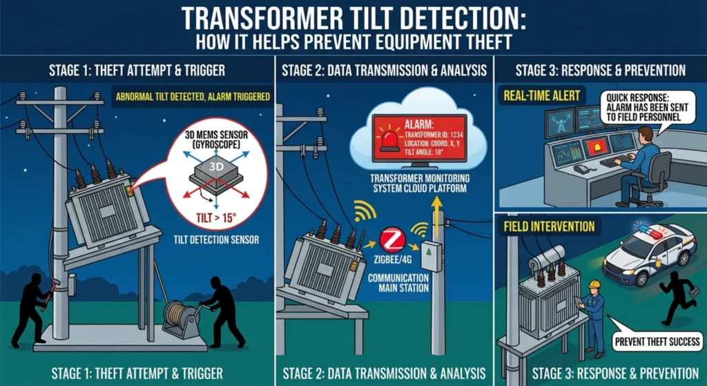
The first two rows are where an attitude channel is at its most valuable, because it is the only signal in the set that reports a state rather than an instant. A jacking event produces an impact when the tool seats and again when the load transfers, but between those two moments the useful information is that the unit is no longer sitting flat, and that condition is visible for as long as the crew keeps working. An operator who receives that reading while it is still true has a decision to make involving a site that may still be occupied, which is a different operational situation from one that follows a completed theft, and the vibration page covers the impact and rhythmic signals that arrive alongside it.
Lifting detection also carries the clearest false-alarm profile of the three, which is useful when an operator is deciding how much filtering to apply. Nothing legitimate lifts a service transformer off its mounting except maintenance, and planned work is scheduled, so an unplanned lift is close to a self-defining event. The residual noise comes from cranes and excavators working nearby on construction sites and from road maintenance equipment passing close to pole-mounted units, both of which produce short attitude changes on the support structure rather than on the unit, and both of which are separated by confining the attitude channel to the unit itself rather than to the pole.
Combining Tilt With Vibration, Cable and Tamper Signals
Tilt, vibration, cable continuity and enclosure state each cover a different segment of the same removal sequence, and the value of combining them comes from the fact that a crew cannot avoid producing a signal in at least one of the four segments. This is also where transformer inclination monitoring is usually described, because the term is used for the continuous attitude channel that sits underneath the alarm logic and logs a unit’s long-term posture.
| Segment of the sequence | Signal that covers it | What it reports |
|---|---|---|
| Approach and cable work | Continuity and earth loop | A conductor opened before the unit was touched |
| Attack on the enclosure | Tamper switch and door contact | The cabinet or cover was opened |
| Tool work and jacking | Vibration and impact | Force applied to the tank or base, in bursts |
| Lifting and loading | Transformer tilt detection and displacement | The unit stopped being level, or moved off its base |
Reading the table as a timeline rather than as a list is what makes it useful at specification time. A continuity channel covers the earliest stage and gives the longest warning, and it is the cheapest to install. An enclosure channel covers the stage where a crew is working on the cabinet rather than on the mounting. A vibration channel covers the middle of the sequence, where tools are being used, and it is the only one that can name the character of the work. The attitude and displacement channels cover the end of the sequence, where the unit is being moved, and they are the only ones that report a condition which persists long enough to be acted on.
The second reason to combine them is the confirmation rule, which is the main defence against false alarms in the whole system. Any single channel applied to a rural site with weather, livestock and passing machinery will produce events that a human has to dismiss, and the honest way to reduce that load is not to raise thresholds until real events are missed but to require agreement. A vibration event that arrives with a continuity break is a different proposition from a vibration event alone. An attitude change that arrives with an enclosure alarm is a different proposition from an attitude change that arrives on a cold morning with no other activity. The combination is what turns a noisy channel into a decision, and the cable cutting detection and tampering detection pages describe the two signals most often paired with attitude in this way. The transformer theft monitoring page covers the operational side, including what a control room is expected to do with an event once it arrives.
How to Reduce False Tilt Alarms
False tilt alarms come from four sources, and naming them is the fastest way to design against them: thermal movement of the mounting, slow ground settlement, wind load on the support structure, and the passage of vehicles, livestock or machinery near the installation. Each has a different signature, and each is addressed by a different control rather than by one global sensitivity setting.
| Source | Signature | Control that works |
|---|---|---|
| Thermal movement of bracket | Slow, diurnal, reverses with temperature | Compensation or a wider low band |
| Ground settlement | Slow, directional, irreversible | Periodic re-capture of the reference |
| Wind on support | Fast, oscillating, returns to zero | Require persistence before an event |
| Passing traffic or livestock | Brief, no correlation with other channels | Confirmation from a second channel |
The first control is to require persistence, which means that a change must hold for a defined period before it becomes an event. Wind is the clearest case: it moves the structure quickly and returns it, so a rule that waits thirty seconds filters almost all of it while a jack, which never returns the unit to level on its own, passes through untouched. The second is to separate the low band from the alarm band, which means treating small angles as information for the maintenance log rather than as events for the operator. A settlement trend that accumulates a quarter of a degree over a season is worth knowing about and is not worth waking anybody, and folding it into the same channel as theft gives the operator a reason to distrust the channel.
[PERSONAL EXPERIENCE] The third control is the periodic re-capture of the reference, which is the maintenance action that most directly keeps a tilt programme honest. Ground moves, pilings settle, and a bracket that was true in spring is not necessarily true in autumn, so a channel that is never re-zeroed gradually accumulates an offset until either it alarms permanently or somebody widens the threshold to silence it. A scheduled re-capture at a fixed interval, with the old reference retained for comparison, turns that drift into a tracked quantity rather than a slow failure. Those four controls are what keep the attitude channel trusted through several seasons rather than only through its first commissioning, and the confirmation rule is the only one that also improves detection rather than only rejection.
Choosing and Installing a Tilt Sensor
Choosing a sensor for this application means matching four properties to the site rather than buying the highest specification available, and the four are the angle range the mounting can plausibly reach, the angular resolution the site’s noise floor permits, the temperature behaviour of the zero point, and the ingress and power arrangements the installation demands.
| Property | What to specify | Why it matters here |
|---|---|---|
| Angle range | Wide enough for handling and transport, typically ±30° or better | A unit being removed exceeds the operating range |
| Resolution | Below the site’s mechanical noise floor, usually 0.1° or finer | Digits finer than the noise are not information |
| Temperature behaviour | Zero-point drift better than 0.02° per °C across the site’s band | Drift appears as a false tilt over seasons |
| Ingress protection | IP66 or IP67 for the mounting position | The device lives outside for a decade |
| Power and backup | Sufficient to cover the longest expected outage, 24 to 72 hours | Protection that fails with the mains is not protection |
Mounting position decides what the channel can see, and the usual failure is to mount the sensor somewhere convenient rather than somewhere representative. The sensor measures the attitude of whatever it is fixed to, so a device bolted to a pole reports the pole’s movement, and a device bolted to the tank reports the tank’s. The recommendation for a pole-mounted unit is to fix the channel to the transformer body or to a bracket rigidly tied to it, and to avoid the pole itself, because the pole is a structure that moves in wind and its movement tells the operator nothing about the unit. On pad-mounted equipment the choice is between the tank, the base and the enclosure, and the same principle applies: pick the member whose attitude changes when the unit is moved and stays put when the wind blows.
| Mounting position | Sees | Blind to |
|---|---|---|
| Tank wall or lid | Levering, jacking and any attitude change of the unit | Movement that leaves the body level |
| Mounting base or plinth | Jacking, sliding and support movement | Rotation of the body about a vertical axis |
| Support pole or bracket | Whole-structure movement, including wind | Which part of the assembly actually moved |
| Inside the cabinet | Nothing useful for removal detection | Essentially the whole sequence |
The last row is worth stating plainly because it is a common design error driven by convenience. A tilt channel mounted inside the enclosure measures the attitude of the enclosure, which is fixed to the unit and does move with it, but the cabinet is also the part a crew opens first and the part most likely to be disturbed by maintenance, so it introduces noise that the tank wall does not. The practical rule is to mount the channel on the member whose movement is the event of interest, and to keep the tamper function on the enclosure where it belongs. Two mounting points, one on the body and one on the base, cover the removal sequence well enough for most districts, and the cost of the second point is small compared with the cost of discovering the blind spot after an incident.
Limitations of Tilt Detection
The limits of transformer tilt detection are structural rather than a matter of tuning, and they should be written into the specification before the hardware is ordered rather than discovered in operation, because the most important of them cannot be designed away at all. The method measures an angle, and an angle is a relative quantity, which is exactly where its blind spot lives.
- It sees relative angle, not absolute position. A crew that removes the unit together with its mounting generates no angle change, so the channel stays quiet through a complete theft.
- It cannot identify anyone. An attitude change says the unit moved. It says nothing about who moved it, and it is not evidence on its own.
- Very slow removal stays inside the low band. A crew willing to spend a whole night on one unit can keep the change inside the settlement range, where the rule is designed to stay quiet.
- A badly commissioned reference disables the protection. If the zero is captured before the plinth has settled, every later reading is measured against a moving origin and the thresholds lose their meaning.
- The sensor is reachable and therefore attackable. A device mounted on an accessible tank can be defeated, disconnected or re-zeroed by the same crew it is meant to detect.
- Reference drift is a recurring cost, not a one-off. Settlement continues for years, so the re-capture interval is a maintenance commitment for the life of the installation.
| Limit | Why it exists | What covers the gap |
|---|---|---|
| Whole-assembly removal | No relative angle is generated | Vibration, continuity and displacement |
| Very slow removal | Change stays inside the low band | Longer-horizon trend analysis |
| Rotation about a vertical axis | Attitude change is small for a large movement | Displacement or satellite positioning |
| Sensor as a target | The device is accessible to the same crew | Concealment and tamper state on the device |
| Reference drift | Settlement shifts the baseline over time | Scheduled re-capture of the reference |
The first row is the one that decides whether a tilt programme is planned honestly. If a district’s theft pattern involves units on concrete plinths being cut free, lifted a few degrees and loaded, then attitude is the right instrument and the thresholds in this page apply directly. If the pattern involves the mounting itself being unbolted from a pad and the whole assembly being taken, then the attitude channel may never see a change, and the programme has to lean on continuity, vibration and displacement instead. Neither pattern is unusual, and the difference is a matter of local history rather than of engineering preference.
The remaining limits are all manageable and all have the same shape: they are reasons to hold the channel to a realistic standard rather than reasons to distrust it. A slow removal takes hours, which is enough time for a trend rule to separate it from settlement, provided the reference is maintained. Rotation about a vertical axis is rare in this application because it is not how a transformer is removed, but where sliding bases exist it is worth a displacement channel. A sensor that can be reached by the crew is a sensor that can be defeated, which is an argument for mounting it where it is not the easiest thing to find and for having the device report its own enclosure state. Reference drift is a maintenance item, not a design flaw, and it is covered by the re-capture interval described above.
How Houfeng Delivers Tilt Detection
A tilt programme is delivered as a configured installation rather than as a box of sensors, and the four steps below are the sequence that keeps the channel usable after the first weather cycle rather than only on the day it was commissioned. The order matters because each step depends on the one before it.
- Site survey. Each unit is inspected for mounting type, base condition and the direction from which a crew could most easily apply force, so that the sensing points and the displacement axis, where fitted, follow the likely line of movement.
- Reference capture. The zero position is recorded after the mounting has settled and under conditions close to the seasonal average, with the date and ambient temperature written into the commissioning record so that a later maintainer can judge the baseline.
- Threshold configuration. The angle and time pairs are set from the risk profile rather than from a default list, with a low band for the maintenance log, a main alarm band, and an immediate band for large changes that needs no persistence check.
- Outputs and confirmation. A local output is configured alongside the remote monitoring communication path so that an event survives a failed link, the confirmation rules are tested against the site’s other channels, and the escalation list is exercised with a live test alarm rather than assumed.
The commercial step after that is a quotation rather than a specification, and the useful way to start it is with the details that actually determine the configuration. If you are scoping a district, send us your requirement with the mounting types, the site list and the loss record for each area, and an application engineer will return a per-site attitude and displacement plan built around the transformer anti-theft monitoring device. You can request a datasheet for the reference configuration first if you would rather compare the input options before committing to a layout.
Frequently Asked Questions
What is transformer tilt detection? It is a monitoring method that measures the attitude of a transformer against a reference position recorded while the site was undisturbed, and raises an event when that attitude changes by more than a set angle within a set time. It detects movement of the unit rather than force applied to it, which is what allows it to report a removal that is still in progress.
What tilt threshold indicates tampering? There is no single number, because a threshold is always an angle paired with a time window. A common starting point is one to two degrees within a minute for a main alarm and any change over five degrees as an immediate event. The same angle reached over months is usually settlement, which is why the window matters as much as the angle.
How does a transformer tilt sensor work? It resolves the direction of gravity in its own frame, usually with a micro-electromechanical accelerometer, stores the position it measured when the site was commissioned, and reports the difference between the current reading and that stored reference. The change is then tested against the configured angle and time rules.
Can tilt detection identify theft rather than only movement? It identifies movement, and the inference that the movement is unauthorised comes from time, direction and correlation. A change that is fast, directional and accompanied by a second channel is treated as deliberate, and that combination is what separates a theft event from settlement or wind in practice.
Does it work on pole-mounted transformers? It does, and the mounting rule is what makes it work. The sensor should be fixed to the transformer body or to a bracket rigidly tied to it rather than to the pole, because the pole moves in wind and its movement is not the event of interest.
How is it different from displacement detection? Attitude detects rotation and displacement detects translation, and they fail in opposite directions. A unit levered up at one corner changes its attitude without moving far, while a unit slid along a pad moves without changing its attitude, so sites with sliding or unbolted bases usually carry both channels. The transformer theft detection page places both within the wider sensor set.
Conclusion and References
Transformer tilt detection does one narrow job well: it reports that a unit is no longer sitting the way it was installed, and it reports it while the change is still happening, which is the only window in a removal sequence where an operator can still change the outcome. Everything else in the discipline follows from taking that job seriously, which in practice means treating the threshold as an angle and a time together, keeping the reference honest, and accepting that attitude alone will not see a unit that is taken complete with its mounting.
The engineering value of the channel is that it is cheap to add to an installation that already has a controller, and the engineering risk is that a badly commissioned reference makes it a nuisance rather than a protection. Both facts point the same way: the sensor is not the hard part, and the transformer anti-theft monitoring system page describes the controller the channel is usually commissioned into. If you are specifying a programme and want a second opinion on the thresholds before installation, contact us with the mounting types and the site conditions and we will work through the pairs with you.
Sources
- IEC 60721-3-2:2018, Classification of environmental conditions — Part 3-2: Classification of groups of environmental parameters and their severities — Transportation and handling. IEC Webstore
- IEC 60068-2-27:2008, Environmental testing — Part 2-27: Tests — Test Ea and guidance: Shock. IEC Webstore
- IEEE C57.12.28-2023, IEEE Standard for Pad-Mounted Equipment — Enclosure Integrity. IEEE Xplore
Written by the engineering content team at Baoding Houfeng Trading Co., Ltd., which works with utilities, EPC contractors and industrial operators on transformer monitoring and protection projects. Technically reviewed by [Reviewer name], senior protection and metering engineer, [X] years in distribution network operations (to be confirmed by the client). Last updated: 4 October 2026.