

Transformer tampering detection is the practice of catching unauthorized physical interference with a distribution transformer, such as an opened compartment, a removed cover, a forced lock or a drilled tank, before the unit is lost. It differs from condition monitoring. The events it looks for are caused by people, not by the machine, and every design choice in this page follows from that difference.
Key Takeaways
- Tampering is almost always a prelude to theft, and it follows a predictable sequence. An alarm raised at the first sign of interference buys hours of response time that a theft alarm cannot.
- The five detectable method families are enclosure opening, cover removal, prying, drilling and interference with security hardware. Each leaves a distinct physical trace that a specific sensor type can catch.
- A transformer tamper sensor measures a switch state, not a condition. Where the switch is mounted decides what it can and cannot see.
- Vibration belongs in this page only as one judgement: how to tell an impact transient from normal load hum. Everything else about vibration is covered by the dedicated vibration monitoring page.
- Tamper sensors can be defeated. A scoping document that does not say so honestly will produce a fleet that operators stop trusting within a year.
What Is Transformer Tampering?
Transformer tampering is any deliberate physical interference with a transformer or its compartments by someone who has no authorisation to touch it, and transformer tampering detection exists because that interference is the visible first step of nearly every organised theft the industry records. The interfering party usually needs minutes of undisturbed access. They may open a cabinet door to reach the LV terminals, unbolt a tank cover, pry a lid away from its frame, drill through steel to drain oil, or dismantle security hardware such as locks and anti-theft studs. Each action differs from normal operation in one decisive way. It changes the physical state of the enclosure, and that change can be wired to an alarm.
[UNIQUE INSIGHT] The most useful mental model is that the enclosure itself becomes a witness. A crew that approaches with tools must cross a boundary. Every crossing (door, cover, panel, plinth, cabinet) is a place where a switch, a contact or a sensor can be waiting.
What the word enclosure means also changes with the asset. A pole-mounted unit exposes a tank and a small terminal chamber; a pad-mounted transformer presents cabinet doors at ground level to anyone who walks past; a compact substation is a walk-in building with its own door hierarchy. The same sensor logic applies to all three, but the monitored set and the switch count differ, which is one more reason the site survey comes before the quotation rather than after it.
Common signs of tampering share one property: they are visible to an inspector but only after the fact. Scratched paint around a cover, sheared padlock hasps, fresh tool marks on bolt heads and a door that no longer seats flush all tell the same story in retrospect. The purpose of detection is to convert those after-the-fact signs into a signal raised while the crew is still present.
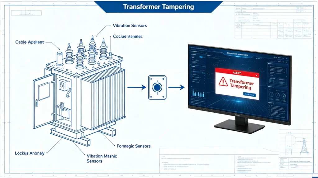
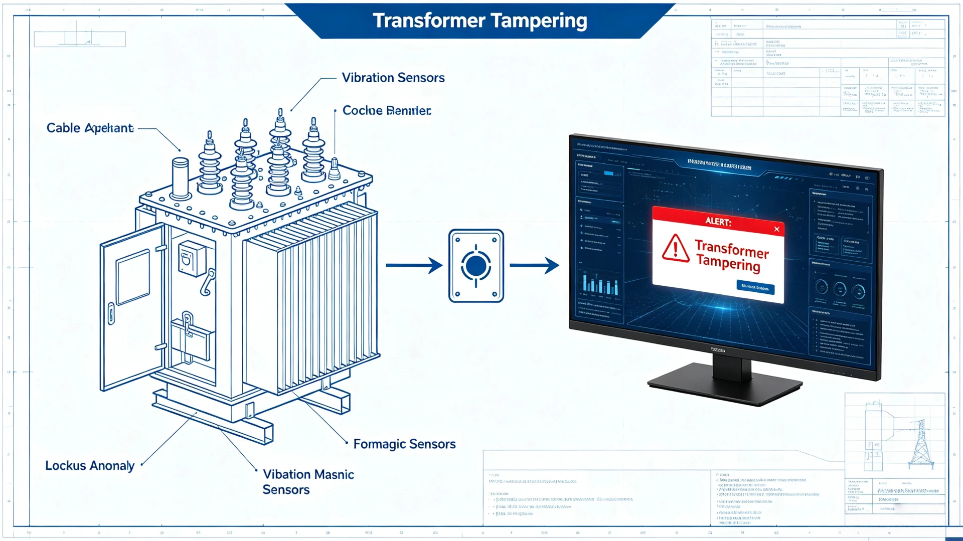
Figure 1. Sensor points on a distribution transformer feeding a monitoring screen that raises a tampering alert.
What Types of Tampering Can Be Detected?
Practically everything a crew does to a transformer before the lift falls into five method families, and transformer tampering detection works by matching each family to the physical trace it leaves behind, so the table below is ordered by how often the methods appear in incident records rather than by how dramatic they sound. Each row pairs the action with the sensing route that catches it.
| Method | What the crew actually does | Physical trace | How it is sensed |
|---|---|---|---|
| Enclosure opening | Opens the cabinet or terminal box door | Door position changes; light enters the bay | Door or tamper switch |
| Cover removal | Unbolts or lifts the tank or compartment cover | Bolt heads disturbed; gap opens at the frame | Cover switch, gap sensor |
| Prying | Forces a lid or panel with a bar | Deformation, impact transients | Tilt or vibration burst |
| Drilling and cutting | Drills the tank to reach oil or internals | Local impact sequence, metal debris | Vibration burst on the tank wall |
| Security hardware interference | Cuts locks, removes studs or earthing | Continuity broken on the protected circuit | Continuity monitoring |
Drilling deserves one comment. It is slow and noisy at the tank wall, which makes it one of the easiest methods to catch with a sensor, and one of the rarest in practice because organised crews prefer methods that finish faster. Detection effort should follow incident records, not the theoretical list.
What Does a Transformer Tamper Sensor Actually Measure?
A transformer tamper sensor measures a switch state or a short transient rather than a continuous condition, which is exactly why it is cheap, low-power and fast, and also why placement and wiring matter more to the outcome than anything written on the sensor datasheet. Four sensor types do nearly all of the work.
| Sensor type | What it measures | Typical trigger | Blind spot |
|---|---|---|---|
| Door and cover switches | Open/closed state of a movable part | Door opened, cover lifted | Anything that does not move the monitored part |
| Tilt sensors | Change of inclination | Unit jacked or pried | Slow rotation below threshold |
| Vibration burst sensors | Short mechanical transients | Impact, drilling, prying | Sustained slow forces |
| Continuity loops | State of a wired loop through the protected parts | Loop cut, bypassed | Requires the loop to be installed and maintained |
A tamper detection sensor of the switch type is normally a sealed microswitch or a magnetic contact. What matters in practice is not the component but three engineering decisions. The switch should be held closed by the enclosure rather than by its own spring, so cutting the sensor reads as an event. The loop should be supervised, so that a bypass is distinguishable from a fault. And the event record should survive the loss of external power. [PERSONAL EXPERIENCE] Fleets that skipped the supervised-loop detail produced alarms that a crew could silence with a jumper in seconds. The operators discovered this only after a real loss, which is the most expensive way to learn it.
Enclosure Opening and Tamper Switch Placement
Enclosure opening and tamper switch placement are the same subject, because a switch can only report the part of the enclosure it watches: a switch on the LV compartment door says nothing about the HV bay, and a switch on the cabinet door says nothing about a tank cover removed from below, so placement is decided by walking the incident sequence backwards and wiring the openings the crew actually uses.
| Placement | What it sees | What it misses |
|---|---|---|
| LV compartment door | Most common entry point | HV bay, tank cover |
| HV bay panel | Direct approach to bushings | LV side work |
| Tank or compartment cover | Cover removal and prying | Side cabinets |
| Plinth and base skirt | Under-base access, jacking | Work above the base |
| Controller housing itself | Tampering with the detector | Everything else |
A survey that ends in a drawing beats a survey that ends in a feeling. For each unit, list every opening, mark which ones the incident record names, and decide for each whether it gets a switch, joins a supervised loop, or is deliberately accepted as a gap with the reason written down. The written-down part matters more than it sounds. When the fleet changes hands or the contractor changes, the drawing is what stops the next crew from reconnecting an opening that was closed for a reason nobody remembered.
Two rules keep the table honest. First, the monitored set must include the entry the local incident record says crews actually use, which is why the survey starts with the utility’s own loss data rather than with a catalogue. Second, every monitored opening must close the loop electrically through the sensor. A door left ajar, a connector undone and a wire cut must all produce events rather than silence. Enclosure integrity itself is standardised. IEC 62262:2002+AMD1:2021 classifies how much mechanical impact an enclosure withstands (the IK code), which is the specification line to quote when the goal is to slow the opening long enough for the alarm to matter.
How a Tamper Signal Reaches the Right Person
The path from a switch state to a phone in a duty officer’s pocket has five links, and this page covers only the first two because the full event chain is the subject of the transformer theft detection overview. In brief: the switch state feeds a controller, the controller evaluates it against thresholds, a local output can sound immediately, and the event travels over the site’s communication link to whoever is on the response list. The part that decides whether the alarm is useful is the last step, not the first. An event delivered to an unmonitored inbox is indistinguishable from no event at all.
The response list itself needs engineering. A tamper alarm at three in the morning is only as good as the number it wakes, and the escalation rule has to say what happens when the first name does not answer within the agreed window. Fleets that write the escalation into the commissioning document treat it as configuration; fleets that leave it to a group chat discover the gap during the first real event, which is the wrong time to learn who is actually on call.
Telling Tamper Vibration From Normal Operation
Vibration earns exactly one judgement on this page, and it is the judgement that separates an interference event from the normal life of the unit: a working transformer hums at its load frequency with harmonics that are steady and rhythmic, while interference produces short, irregular transients that arrive in bursts and stop when the work stops. The practical test is duration and pattern, not loudness. That is why a burst-type sensor with a duration filter can sit on the same tank as a condition-monitoring sensor without the two fighting each other.
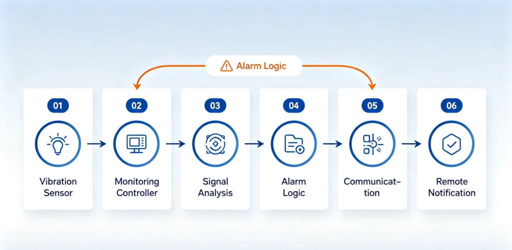
Figure 2. The sensing chain behind the tamper vibration judgement, from sensor to remote notification.
| Signal | Pattern | Duration | Interpretation |
|---|---|---|---|
| Load hum | Steady, load-correlated | Continuous | Normal |
| Impact transient | Sharp onset, irregular | Milliseconds to seconds | Interference candidate |
| Sustained rattle | Repetitive, wind or loose part | Minutes, weather-correlated | Nuisance source |
Everything beyond this judgement belongs to the vibration monitoring page, including sensor choice for theft-specific signatures, forced-removal patterns and threshold tuning by season.
Why Tampering Almost Always Precedes Theft
Organised losses follow a sequence stable enough to plan against, and the plan works only if each step in that sequence is detected by the sensor matched to it, which is what the table below is for. A site is visited first. LV cables are cut and stripped days before the unit disappears, which the cable cutting detection page treats in depth. The enclosure is then opened to disconnect metering. Only then does the lift happen.
| Step in the sequence | Typical timing | Alarm available | Value of the alarm |
|---|---|---|---|
| Scouting visit | Days ahead | None from the unit itself | Site logs and neighbours matter here |
| Cable cutting | Days ahead | Continuity and power events | High; see the cable cutting page |
| Enclosure opening | Minutes to hours before the lift | Tamper switch | Highest: transformer tampering detection fires while the crew is still on site |
| Lifting | The loss itself | Tilt and movement | Recovery odds, not prevention |
[UNIQUE INSIGHT] This ordering is the economic argument for tamper sensing. An alarm at the opening step converts a recovery problem into a response problem, and response is cheaper than replacement in every loss record this company has seen. The prevention guide explains how physical hardening and monitoring combine. The distribution transformer theft page explains what the losses look like when the sequence completes.
Can a Tamper Sensor Be Defeated?
It can, and an honest specification says so before the buyer discovers the fact during an incident instead, because three defeat methods dominate in practice and every one of them was preventable at design time. An unsupervised switch loop can be shorted or bypassed. A crew working slowly enough can keep forces under threshold. A communication link can be jammed so the event never leaves the site. Each has a known countermeasure, and the countermeasures are cheap at design time and expensive to retrofit.
| Defeat method | What it exploits | Countermeasure |
|---|---|---|
| Loop bypass | Unsupervised circuit | Supervised loop with end-of-line resistance |
| Slow prying | Threshold set for impacts | Two correlated signals, plus tilt for slow movement |
| Jamming | Single-path communication | Store events on device, forward when the link returns |
| Detector removal | Controller itself unmonitored | Tamper switch inside the controller housing |
[UNIQUE INSIGHT] The last row is the one most fleets miss. The controller that listens for tampering is itself the most valuable target in the enclosure, because silencing it silences everything. A housing switch costs almost nothing and converts the most likely attack on the system into the loudest alarm it can raise.
Limitations of Transformer Tampering Detection
Transformer tampering detection has hard limits that sales material tends to blur, and writing those limits into the scope is the fastest way to build a programme that survives contact with operations.
- It cannot identify anyone. A switch reports a state, not a person. Prosecution depends on evidence gathered after the alarm, such as camera records or site logs.
- It cannot stop a prepared crew. Delay comes from physical hardening. Detection only shortens the time between the act and the response.
- It fails without power and coverage. The controller and its battery must ride through the outage that accompanies many theft attempts. Sites without a workable communication path need an honest local-only design with scheduled inspection.
- It only sees what it watches. Placement defines coverage, and every unmonitored opening is a documented gap, not a hypothetical one.
- It degrades without maintenance. Doors dropped by wind, corroded contacts and loose connectors all erode the signal. The device that is never walked never fails loudly.
- It produces nuisance alarms. A door on an exposed ridge will be opened by weather eventually, and the response procedure has to survive that first false alarm or the whole system gets ignored.
Frequently Asked Questions
How to detect transformer tampering on a live network? Transformer tampering detection on a live network starts with the enclosure states that crews must change to do the work: doors, covers, panels and the controller housing, each wired through a supervised switch. Correlate those states with continuity on protected circuits and with loss-of-supply events. The combination raises an alarm at the first physical step instead of the last, and the event record gives the response team something to act on.
What types of tampering can be detected? Enclosure opening, cover removal, prying, drilling and interference with security hardware, as tabulated above. The first two are caught directly by switch state, prying and drilling by short transients, and hardware interference by continuity. Anything the utility’s incident record shows as a local habit should be added to the monitored set before hardware is ordered.
Can a tamper sensor be defeated? Yes. Unsupervised loops can be bypassed, slow prying can stay under an impact threshold and communication can be jammed. Supervised loops, two correlated signals, tilt sensing for slow movement and on-device event storage close most of these gaps. A housing switch on the controller closes the one most fleets forget.
Can tamper sensing be retrofitted to an existing transformer? In most cases yes. Switches mount on doors, covers and cabinets without de-energising the unit, and the controller takes supply from the LV side with battery backup. The retrofit decision that needs real planning is the same as for a new build. Which openings does the local incident record say must be watched, and does that pole have a reporting path?
Should tamper sensing run alone? No single signal carries a programme. Tamper states pair naturally with tilt (someone is opening and lifting), with continuity (cables went first) and with loss-of-supply events (the outage is not routine). The technical overview page shows how the pieces form one chain.
Conclusion and References
Transformer tampering detection works because interference with the enclosure is a state change, and state changes can be wired to an alarm that reaches a person who can still do something. The engineering content is in the placements and the loops. Which openings are watched, whether the loop is supervised, whether the event survives the outage, and who is on the list when the alarm fires. Get those four decisions right and the unit calls for help while the crew is still standing next to it.
If you are scoping a district rather than a single unit, send us your requirement with the site list and the incident record for each area. An application engineer will return a per-site placement plan and a supervised-loop schedule built around the transformer anti-theft monitoring device, and you can request a datasheet for the reference configuration first.
Sources
- IEC 62262:2002+AMD1:2021 CSV, Degrees of protection provided by enclosures for electrical equipment against external mechanical impacts (IK code). IEC Webstore
- IEC 60529:1989, Degrees of protection provided by enclosures (IP code), cited as the companion ingress standard to the IK code.
- IEEE C57.12.28-2023, Pad-Mounted Equipment Enclosure Integrity, cited for enclosure integrity expectations on pad-mounted assets.
Written by the engineering content team at Baoding Houfeng Trading Co., Ltd., works with utilities, EPC contractors and industrial operators on transformer monitoring and protection projects. Technically reviewed by [Reviewer name], senior protection and metering engineer, [X] years in distribution network operations (to be confirmed by the client). Last updated: 20 September 2026.