

Protect pole mounted transformers from theft by matching the sensor set to the removal sequence that a pole installation actually permits, because a theft seven metres above a roadside is a different operation from one inside a pad-mounted enclosure, and the difference is geometry rather than difficulty.
A pole-mounted unit hangs on a bolted steel connection that was designed to be assembled on site by two people with hand tools. That same connection can be taken apart on site by two people with hand tools. The unit is also small enough to be lifted by equipment that every distribution contractor already owns, and its mounting height doubles as the working platform for whoever is dismantling it, so no fence, no gate and no approach road has to be defeated first.
This page treats the installation form itself: what the pole, the bracket and the platform change about how a theft is carried out, what signal appears first in each case, and where each of those signals should be intercepted. Network structure, supply radius and patrol frequency belong to the rural distribution page, and the choice between protection principles belongs to the prevention overview.
Key Takeaways
- The pole form decides which thefts are available, not how hard they are. A unit that can be unbolted can be lowered whole; a unit that cannot be opened cannot have its windings pulled in place.
- Signal order matters more than signal presence. In a whole-unit removal the mounting angle changes before the load current disappears, so a system watching only for loss of supply learns about the theft after the vehicle has left.
- “Is the transformer still there?” is not a usable test. A drained tank with its windings cut out stays bolted to the pole and passes a visual patrol, a monthly photograph and an asset count.
- At a pole site the power budget is decided before the sensor list. There is no low-voltage auxiliary supply and nowhere to hide a cabinet, so autonomy becomes a design constant rather than an equipment property.
- A monitor that can be pulled off the pole creates a silent site, and a silent site reads as a normal site on most platforms. Removal of the monitor has to generate its own event.
- Enclosure ratings do not answer this threat. Impact and ingress ratings describe how hard it is to get into the box, and no part of a pole-mounted removal requires getting into it.
What Is Pole Mounted Transformer Security?
Pole mounted transformer security is the set of measures that slow a removal down, notice that one is being attempted, and deliver that notice to somebody who is not standing at the pole, and the three jobs are bought, commissioned and abandoned separately. That separation is why a pole carrying a cage, a lock and a sensor can still be stripped without anybody at the utility hearing about it, and it is why the order in which the layers are commissioned matters more than the length of the list.
The installation form moves the boundary of each job. On a ground-mounted unit the enclosure is the barrier, so physical protection has something to act on and the sensor set only has to report what happens after the barrier is defeated. On a pole-mounted unit there is no barrier to build: nothing can be placed between the unit and the ground except the fixings that already hold it up, and those fixings have to remain removable or the utility cannot service the transformer. The physical layer therefore acts on time, not on access, and the sensing layer has to cover the whole distance between the platform and the ground rather than a single door.
| Installation form | Attack direction | Access required | Can the unit leave whole? | Dominant target |
|---|---|---|---|---|
| Single-pole bracket, 10–50 kVA | Vertical, one side only | Ladder, no site permission | Yes, with a rope and two people | The unit, then the leads |
| Two-pole platform, up to 500 kVA | Vertical, between the poles | Ladder plus a chain block or small crane | Yes, within the platform’s own load limit | The unit |
| Ground-mounted pad or kiosk | Horizontal, through the enclosure | Hand tools; the enclosure is the barrier | Rarely; windings leave through the door | Windings and busbars |
| Pole top, single phase, 10–25 kVA | Vertical, from the pole itself | Pole steps and a safety belt | Yes, and often by cutting it down | The unit and the earth conductor |
The distinction matters for procurement because the two forms are usually bought on the same schedule and priced against the same specification, and a specification written around a pad-mounted enclosure will specify an ingress rating and a door contact while leaving the array of channels that a pole installation needs completely unaddressed. Those channels are set out later on this page, and the transformer anti-theft monitoring system they feed into is described on the cluster hub, which is the right place to start if the architecture is still open.
One boundary is worth stating before the details. Everything on this page is about the mounting form. Where the transformers sit in the network, how far the supply radius runs and how often a crew passes the pole are treated separately on the rural transformer theft prevention page, and the two pages should be read together rather than as alternatives.
Why Are Pole Mounted Transformers Vulnerable to Theft?
Pole mounted transformers are vulnerable to theft because three structural features of the installation work in the attacker’s favour at the same time: the mounting is a bolted connection assembled on site, the mounting height is reachable from a ladder, and the capacity band keeps the unit’s mass inside the lifting capacity of an ordinary truck crane. None of the three is a defect. Each is the direct consequence of a design decision that makes the transformer serviceable, and serviceability and removability are the same property viewed from opposite ends.
The first feature is the mounting itself. A distribution transformer on a two-pole platform is held by brackets bolted through the pole or through a steel crossarm, and the joints are exposed, standard and accessible because they were placed there to be tightened and inspected. Any joint that can be tightened from a ladder can be loosened from a ladder, and the reversal takes a fraction of the time the assembly took because nothing has to be aligned, levelled or torqued to a specification.
The second feature is that the elevation protects nothing. Height is often treated as a deterrent on the assumption that the equipment is out of reach, which is true for the public and false for anyone who arrives with a ladder and a purpose. On the contrary, the platform gives the attacker a stable working position at exactly the height where the transformer’s own terminals, lid bolts and lifting eyes are located, which removes most of the scaffolding and staging work that a ground-level theft would require.
The third feature is the capacity band. IEEE C57.12.20-2023 covers overhead-type distribution transformers of 500 kVA and smaller, with high voltage at 34 500 V and below and low voltage at 7970/13 800Y V and below, and that envelope is where pole-mounted units live. A 50 kVA single-phase unit is light enough to be lowered on a rope by two people; a 500 kVA three-phase unit needs a crane and a truck, and both of those are ordinary contractor equipment rather than anything specialised. On most networks a unit that size is worth several thousand US dollars in copper alone, so the economics of a two-hour job with three people are not marginal.
| Structural feature | What it gives the attacker | What it takes away from the utility |
|---|---|---|
| Bolted, site-assembled mounting | A reversible joint, exposed and standard | Any chance of a tamper-proof fixing on a serviceable part |
| Mounting height of 6–9 m | A ready-made working platform | The assumption that elevation deters |
| Capacity band of 500 kVA and below | A mass inside truck-crane capacity | The assumption that weight deters |
| Long feeder, no permanent staff | Hours of uninterrupted working time | Any hope that a patrol will interrupt the attempt |
The combination explains why pole mounted transformer theft is not simply a harder version of the same crime committed against a fenced substation. The substation theft has to get past a perimeter, a lock and usually a person; the pole theft has to get past a bracket, and the bracket was designed to come off. The transformer theft detection overview sets out how the individual detection channels are chosen and combined, and the sections below deal with what the pole form does to that choice. Whichever channels are chosen, the objective is to protect pole mounted transformers from theft at the point in the sequence where the removal can still be interrupted, and that point is in a different place for each of the three methods that follow.
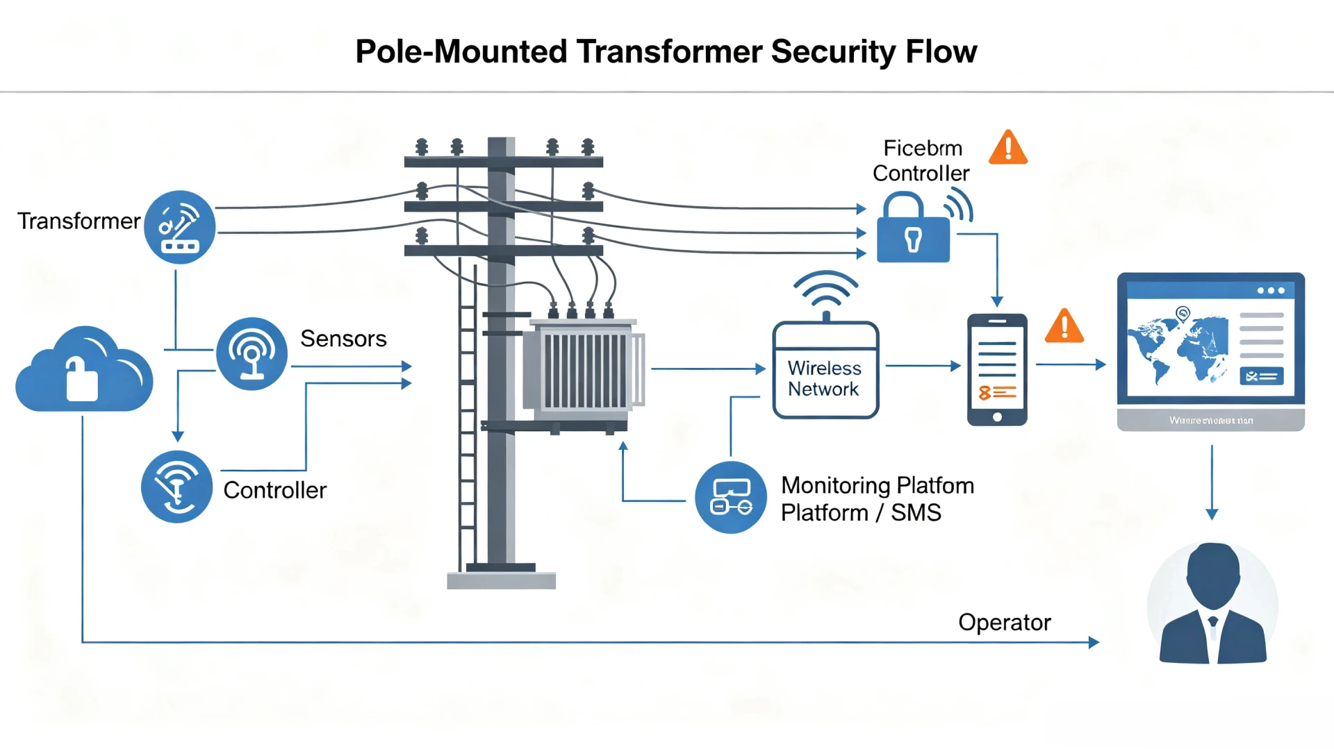
_Figure 1 shows a platform-mounted unit with the two grip points that any removal sequence has to reach: the terminal connections above and the bracket bolts below._
Three Theft Methods That Only Work on Pole-Mounted Units
Three removal methods account for almost every pole-mounted case, and all three depend on the installation form rather than on the value of the transformer: lowering the whole unit on its own mounting hardware, opening the tank in place and pulling the windings, and stripping the conductors and fittings without touching the transformer body at all. Each method leaves a different first signal, and the first signal is what a monitoring design has to be built around, because by the time the last signal appears the equipment is usually gone or already ruined.
[UNIQUE INSIGHT] The practical consequence is that a pole-mounted monitoring design should be organised around the removal sequence rather than around the component list. A specification that lists vibration, tilt, tamper and cable channels without stating the order in which they will move will still alarm eventually, but the alarm arrives at the point where the sequence is already irreversible. Ordering the channels against the sequence is what converts a recording of a theft into an interruption of one.
### Method 1: Lowering the Whole Unit on Its Own Mounting Hardware
The sequence is short and it is always the same. The low-voltage leads and the high-voltage jumper are disconnected at the terminals and tied clear, the mounting brackets are unbolted, and the unit is lowered on a chain block rigged to a temporary gin pole, on a small truck crane, or on a rope if the unit is a small single-phase one. Nothing is disassembled, nothing is opened, and the asset leaves the site intact and resellable or immediately recyclable. Working time for a two-pole platform with three people is commonly twenty to forty-five minutes, and the only part of that time the attacker cannot compress is the unbolting itself.
This method is also the one that is least likely to be interrupted by an outage-based check, because the disconnection at the terminals is the same operation a legitimate crew performs, and a short loss of supply at the end of the sequence is indistinguishable from a fault clearing if the only recorded quantity is the load current. The distinguishing quantity is the mounting angle, because the bracket bolts come out before the unit moves: the tank shifts on its remaining bolts, the attitude changes by a degree or two, and only afterwards does the current disappear. A monitoring rule that requires an attitude change followed by a loss of phase current inside the same window separates the removal from the fault, and it does so on evidence that exists several minutes before the equipment leaves. The transformer tilt detection page covers the sensor side and the threshold logic in detail.
### Method 2: Opening the Tank in Place and Pulling the Windings
The second method never removes the transformer. The tank is drained through the drain valve or opened with a punch, the lid bolts are undone or the tank wall is cut, the coil leads are severed and the windings and busbars are pulled out and carried down. What remains is an empty tank still bolted to the platform, at the correct height, with its bushings in place and its paint intact. Working time is fifteen to thirty minutes, no lifting equipment is required, and the operation makes almost no noise apart from the tools.
This is the method that defeats every check based on presence. A patrol driving past sees a transformer on a pole. A monthly condition photograph shows the same silhouette as last month. An asset register still lists the unit as installed, and the register will keep listing it until somebody opens the tank or measures the load. The only quantities that distinguish this theft from an ordinary failure are the order of events and the internal condition of the tank: the enclosure is opened or the oil temperature departs from the load-expected gradient before the supply is lost, whereas a genuine winding failure produces the loss of supply without any prior enclosure event. A lid contact, an oil-temperature comparison against load current, and a tamper channel on the tank fastenings are what make the difference visible, and the mechanism behind each is described on the transformer tampering detection page.
### Method 3: Stripping Conductors and Fittings Without Touching the Body
The third method takes the parts that are easy to reach and easy to sell. The low-voltage service drop and the jumper leads, the bare earth conductor running down the pole, the terminal connectors on the bushings, the drop-out fuse cutouts and the surge arresters are all removable with hand tools from a ladder, and on many pole-mounted installations some of them are within reach from the ground with a long tool. Copper content per metre of a service drop is high and the resale path is the same scrap route that the windings follow, so the economics favour the small components when the attacker has limited time.
The pole form is what makes this method cheap, because the same conductors on a pad-mounted installation are inside the enclosure and require the door to be opened first. The method is also frequently scheduled rather than forced: a planned outage removes the neutral-to-earth reference that would otherwise make the removal immediately visible, so the theft proceeds inside a window in which an outage is already expected. The signals are the continuity of the low-voltage conductors and of the earth conductor, the loss of a single phase rather than all three, and a change in the current balance between phases that persists after supply is restored. Cable continuity monitoring for exactly this case is covered on the transformer cable cutting detection page.
| Method | Working time | Equipment needed | Signal that appears first | Interception point |
|---|---|---|---|---|
| Whole-unit lowering | 20–45 minutes | Ladder, chain block or small crane, 3 people | Change of mounting angle | Attitude channel plus mounting-bolt tamper |
| In-place tank opening | 15–30 minutes | Hand tools, ladder, container for oil | Enclosure or lid opening, oil-temperature departure | Lid contact, oil comparison, enclosure tamper |
| Conductor and fitting stripping | 5–15 minutes | Hand tools, ladder or long pole tool | Loss of a single phase or of earth continuity | Secondary and earth continuity, phase balance |
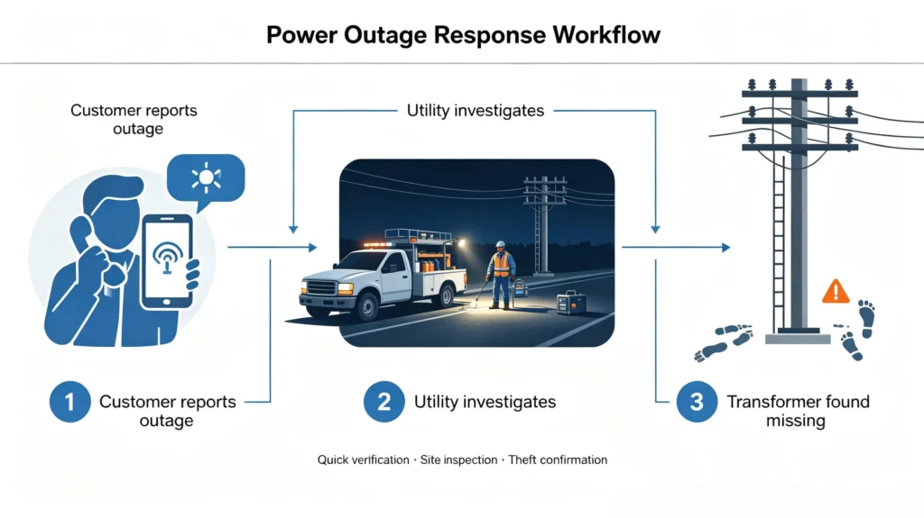
_Figure 2 places the three sequences side by side on the same pole so that the shared working position and the different first signals are visible at once._
What Events a Pole Mounted Security System Should Detect
A pole-mounted system should detect six events in a fixed priority order: a change of mounting attitude, the opening of the tank or its covers, the loss of earth or secondary continuity, the loss of a single phase, the loss of the monitoring unit’s own presence, and the departure of the monitored site from its expected load profile. The order is a response order rather than an importance order, and it is set by how much time each event leaves before the site is lost, which is the only quantity that matters once the alarm has to travel to a person who is several kilometres away.
| Event | Usable signal | Response the event justifies |
|---|---|---|
| Bracket or fixing disturbed | Mounting-bolt tamper switch, micro-change in attitude | Immediate dispatch; this precedes every whole-unit removal |
| Tank or lid opened | Lid contact, enclosure tamper switch | Immediate dispatch; this precedes a winding removal |
| Attitude change without supply loss | Attitude channel beyond the site’s wind baseline | Verify remotely, then dispatch to the nearest site |
| Earth or secondary conductor opened | Continuity loop on the earth and secondary circuits | Investigate within the shift; a single-path repair stop |
| Single phase lost, others healthy | Phase presence and current balance | Correlate with the fault log before dispatch |
| Monitoring unit removed or silent | Heartbeat expiry, unit tamper switch | Treat as an intrusion until proven otherwise |
| Load profile departs from expectation | Current and temperature against the recorded baseline | Schedule inspection; weak on its own, useful in combination |
The channel list is deliberately shorter than the list of things that can be measured at a pole, and the boundary between this page and the four detection pages is worth making explicit. How a vibration channel separates a removal from a passing vehicle belongs to the vibration page, how a tilt threshold is derived from a wind baseline belongs to the tilt page, and how a continuity loop avoids alarming on a service drop that is legitimately isolated belongs to the cable page. What belongs here is which channels a pole installation needs at all, and what their thresholds have to be measured against on an exposed structure.
| Channel | Judgement covered by | Pole-specific point that changes the setting |
|---|---|---|
| Vibration | Vibration monitoring | Wind loading on the tank dominates the baseline |
| Attitude and tilt | Tilt detection | Pole sway moves the reference as well as the tank |
| Earth and secondary continuity | Cable cutting detection | The conductors are outside the enclosure and reachable |
| Enclosure and lid state | Tampering detection | The lid faces upward and is worked on from a ladder |
| Supply and phase state | This page and the hub | A planned outage mimics the theft window |
| Unit presence and heartbeat | This page | The monitor is easier to remove than the transformer |
How to Secure a Pole Mounted Transformer Without a Permanent Power Supply
To secure a pole mounted transformer that has no permanent auxiliary supply, the monitoring equipment has to take its energy from the circuit it is protecting, from a battery sized for the honest reporting duration, or from a small photovoltaic panel, and each of those three choices removes a different margin rather than simply being cheaper or dearer than the others. The decision comes before the sensor list, because a design that runs out of energy stops reporting regardless of which channels were specified.
Current-transformer harvesting is the most elegant option and the least forgiving. The supply is drawn from the protected circuit, so no battery has to be sized for years of service and no panel has to be exposed on the pole, but the harvesting supply disappears at the same moment the protected circuit does, which is precisely when a removal attempt is most likely to be under way. The unit can bridge a short interruption from a small internal cell, and the bridge duration becomes the real specification figure. A design that reports for four hours on the harvest alone will be silent through a theft that begins after a planned outage has run longer than four hours.
Battery operation inverts the problem. The site reports for as long as the battery holds, and that figure is a design constant rather than a property of the equipment: a pack sized at commissioning for seven days of reporting may deliver three after several years of cycling, so the end-of-life state has to be reported as an event instead of being read as a maintenance note. A low-battery warning that arrives as a page nobody owns is equivalent to no warning at all. Small photovoltaic assistance extends the interval and adds a component that sits in the open on a pole, which is itself an item that can be unbolted and resold, so the panel needs the same tamper coverage as the transformer.
| Supply option | Reporting duration | Failure mode | Cost consequence |
|---|---|---|---|
| Current-transformer harvesting | Hours; fixed by the internal cell | Goes silent when the circuit it protects goes dead | Lowest hardware cost, highest design effort |
| Primary battery | Days to weeks; decays with age | Silent at end of life unless that state is alarmed | Replacement cost per site, per cycle |
| Battery with photovoltaic assist | Weeks to months in good latitudes | Panel is removable and is itself a theft target | Extra mounting and tamper coverage |
| Local low-voltage tap | Continuous while the tap is live | Introduces a conductor that is easy to cut | Cheapest online, most predictable failure |
Environmental class is the second decision that the pole form forces, and it is the one most often inherited by accident from a ground-mounted specification. A pole-mounted enclosure occupies a location that is not protected from the weather in any sense, which is the category that IEC 60721-3-4:2019 classifies for stationary use, and the parameters that matter for a sensing design are the mechanical ones: wind-driven motion of both the tank and the pole, thermal cycling between full sun and night, and the ice loading that changes a tank’s apparent attitude without any human involvement. A tilt threshold copied from a pad-mounted site will alarm all winter. The threshold has to be derived from the site’s own recorded wind baseline, and that baseline has to be collected before the alarm rules are commissioned, not after the first false dispatch.
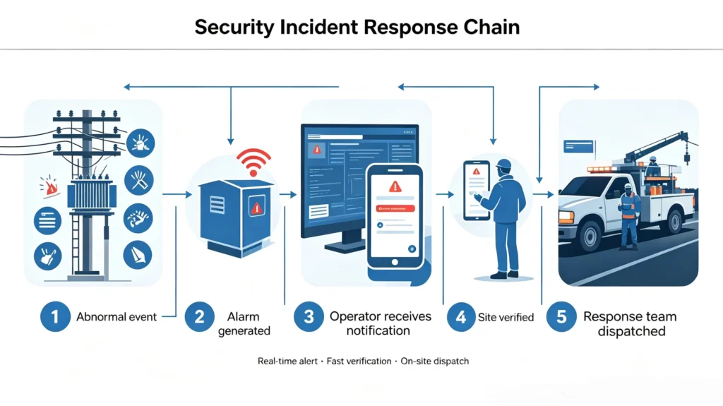
_Figure 3 shows how the energy decision sits under everything else at a pole site: the same sensing points, one controller, and a reporting budget that the battery sets rather than the radio._
The third decision is the communication path, and it is deliberately not developed here. The comparison between cellular options at a pole site belongs to the remote monitoring communication page, and the deployment order for a site with no permanent staff belongs to the theft monitoring for remote substations page. What a pole installation adds to both is the energy arithmetic above: every additional message costs battery, and the reporting interval is therefore a security parameter rather than a convenience setting. Pole top transformer protection is, in the end, a power budget with sensors attached.
Physical Protection vs Remote Monitoring
Physical protection and remote monitoring are not competing options at a pole-mounted installation; they are the two ends of one chain, and the chain is only as strong as the shorter end, which on an exposed pole is almost always the physical one. Physical measures buy time by making the removal slower, and remote measures buy information by making the removal visible, and neither of them produces a prevented theft without the other.
At a pole-mounted site the physical layer is compressed by the installation form itself. There is no perimeter to fence, no gate to lock and no approach to restrict, so the measures available are limited to security hardware on the unit and its fittings: hardened bolts, welded or shielded fasteners, caged terminals, anti-removal brackets and locks on the covers. Each of these adds minutes to the removal, and none of them reports anything. A utility that installs a full set of hardware and stops there has made the theft take longer without changing the outcome, because the attacker who is prepared to spend forty minutes is not stopped by hardware that adds ten. The second layer is the one that changes the arithmetic: continuous monitoring of a pole-mounted site means the attacker can no longer count on a known window of hours, which is the assumption on which the whole method depends.
| Layer | What it does | Who it tells | Failure when used alone |
|---|---|---|---|
| Security hardware on the unit | Adds minutes to the removal | Nobody | Longer theft, same result |
| Local siren or strobe | Interrupts the attacker’s confidence | Whoever is within earshot, usually nobody | Noise heard by an empty field |
| Attitude, tamper and continuity channels | Detects the removal while it is in progress | The control room or duty phone | Detection with no response is a record |
| Escalation and dispatch procedure | Converts the detection into a journey | The crew who actually travel | The only layer that stops the theft |
| Physical and remote layers together | Slows the removal and reports it | The responder, with time to use it | The configuration the other four rows assume |
The division of labour is therefore specific. Hardware decides how long the attacker needs; monitoring decides whether anybody knows; the procedure decides whether knowing was worth anything. The configuration above is the one that has to protect pole mounted transformers from theft on a feeder where the nearest crew is an hour away, and it is the arrangement against which the measures compared elsewhere in this cluster should be read.
How to Choose a System That Will Protect Pole Mounted Transformers From Theft
Choosing equipment for a pole-mounted site starts with six measurements that have nothing to do with equipment: the unit’s capacity and mass, the mounting form and the platform height, the site’s wind exposure, the cellular coverage actually present, the energy option available, and the measured arrival time for a crew. Taken together they determine the channel set and the thresholds, and taken in isolation they produce the common failure of a specification copied from a neighbouring project that had different answers to all six.
| Decision variable or objective | What it settles | Consequence for the design |
|---|---|---|
| Capacity and mass | Nameplate kVA and the lifting equipment the unit requires | Whether whole-unit removal is plausible at all |
| Mounting form and height | Single pole, two-pole platform or kiosk, and platform height in metres | Where the attitude and tamper channels are mounted |
| Wind exposure | Recorded attitude variance over a full weather cycle | The lower bound of every movement threshold |
| Coverage | Signal strength measured at the pole rather than at the office | Which energy option remains affordable |
| Energy option | Harvest, battery, photovoltaic or a local tap | Reporting interval and the heartbeat policy |
| Arrival time | Measured, not estimated, for the worst route in the zone | Whether a movement event justifies dispatch |
| Protect pole mounted transformers from theft on a two-pole platform | Attitude channel plus mounting-hardware tamper, commissioned first | The bracket moves before the unit does, so angle precedes current |
Two of those rows deserve more weight than the rest. Arrival time is the variable that most programmes estimate from a map and then never measure, and it sets the longest reporting interval that can still be useful, because a reporting duration longer than the journey changes nothing. Wind exposure is the variable that most programmes omit entirely, and it sets the shortest threshold that will not produce false dispatches; on an exposed pole the gap between the two can be narrow enough to decide the whole design. Where the gap closes completely, the honest answer is that the attitude channel cannot carry the alarm on its own at that site and the design has to lean on the tamper and continuity channels instead.
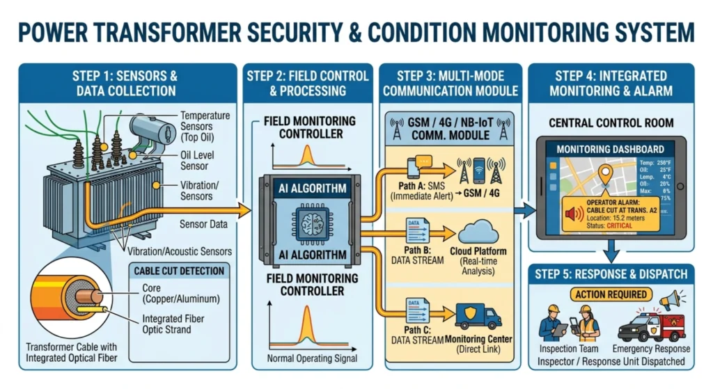
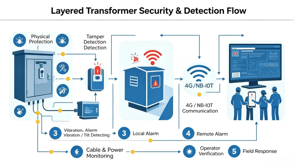
_Figure 4 shows the mounting position and the two channels that are commissioned first on a pole site: the attitude reference on the tank and the tamper switch on the mounting hardware._
Limitations and Boundaries of Pole-Mounted Transformer Protection
Pole-mounted transformer protection has hard limits, and they are worth stating before a specification is written, because each of them is a case where a correctly installed system will still fail to prevent a theft and the failure will be attributed to the equipment. Six of them recur often enough to be planned for rather than discovered.
- It cannot see a removal that never disturbs the angle. A winding extraction performed through an opened lid leaves the mounting untouched, so a design that relies on movement alone is blind to one of the three common methods.
- It sees relative angle, not absolute position. An attitude channel reports that the tank has moved by some amount relative to its own recorded reference; it does not report where the transformer is, and it cannot distinguish a deliberate change from a settling bracket after a storm.
- Wind sets a floor under every movement threshold. At an exposed site the tank and the pole move enough in ordinary weather to occupy part of the threshold band, so sensitivity has to be traded against false dispatches, and the trade is not free in either direction.
- It is silent once the monitor itself is removed. The unit on the pole is easier to unbolt than the transformer beside it, and an alarm platform that treats the last received message as the current state will show a quiet site rather than a missing one.
- Enclosure ratings do not address the threat. Ingress protection and impact resistance describe resistance to being opened and to being struck, while the most common pole-mounted methods require neither, so higher ratings buy weather tolerance and vandal tolerance rather than theft prevention.
- It cannot replace a response. Every channel on this page produces a message, and a message that nobody is assigned to act on converts a prevented theft into a well-documented one, which is the most expensive outcome available.
| Limitation | Practical mitigation | Residual risk after mitigation |
|---|---|---|
| Movement-blind methods | Lid contact and oil comparison commissioned alongside attitude | A lid opened and closed between reports is missed |
| Relative rather than absolute position | Periodic reference re-baselining, recorded in the site file | Slow drift is invisible until it exceeds the band |
| Wind-driven false alarms | Site-specific baseline before commission, staged escalation | Very exposed sites keep a wide dead band |
| Silent site after monitor removal | Heartbeat expiry alarmed, unit tamper switch fitted | Jamming produces the same silence by another route |
| Ratings that do not match the threat | Treat ratings as weather and vandal specification only | No rating substitutes for sensing |
| No response capability | Written escalation with a named owner and a drill | Small teams cannot cover every zone at once |
How Houfeng Supports Pole-Mounted Transformer Programmes
Houfeng supports pole-mounted protection programmes by working from the removal sequence backwards to the channel list, rather than from a standard product configuration forwards to the site, because the two most expensive mistakes on a pole installation are a threshold copied from a ground-mounted project and a reporting interval that is shorter than the journey a crew has to make.
The order that works on a pole feeder is to measure first and specify second. Measure the platform height and the mounting form, record the wind baseline at the exposed sites for a full weather cycle, measure the signal strength at the pole rather than at the nearest town, and measure the arrival time for the worst route in each zone. Those four measurements decide the channels, the thresholds and the autonomy figure, and they cost a few days of field time rather than equipment budget. A programme that starts with the measurements usually finds that a smaller channel set than planned is sufficient, and a programme that starts with the product list usually finds the shortfall in the first winter.
| Delivery step | Measurement it depends on | Deliverable produced |
|---|---|---|
| Site survey | Platform form, mounting height, approach | A site record per pole, in one format |
| Threshold baseline | Recorded attitude variance over a full weather cycle | A dead band per site rather than per project |
| Channel selection | Unit kVA band and the plausible removal method | A channel list with the sequence each channel covers |
| Energy sizing | Measured signal strength and required reporting interval | An autonomy figure and a heartbeat policy |
| Commissioning test | The removal sequence itself, exercised once | A recorded event log for every channel |
| Response drill | Measured arrival time for the worst route | A named owner and an escalation list |
For a first step, request a datasheet for the reference configuration and compare its channel set and autonomy figures against the measurements above, or send us your requirement with the kVA band, the mounting form, the platform height and the arrival time for the zone, and an application engineer will return a channel list, a threshold basis for each movement channel and a reporting-duration calculation. Where a site is already instrumented, supply the recorded baseline instead and the same exercise becomes a review of thresholds rather than a new selection. The device itself is specified on the transformer anti-theft monitoring device page, including the tamper and heartbeat behaviour that a pole installation depends on.
Frequently Asked Questions
What are common pole mounted transformer theft methods? Three methods dominate: lowering the whole unit after unbolting its mounting, opening the tank in place and pulling the windings, and stripping the conductors and fittings without touching the body. The first is the loudest and the fastest to notice, the second is the hardest to detect by inspection, and the third is the cheapest to carry out.
How can I protect pole mounted transformers from theft in an area with no cellular coverage? Choose channels that fail safely when the link is absent, keep the local alarm and the tamper detection, and either accept a longer reporting interval through a satellite or store-and-forward path or accept a shorter one by adding a repeater. The channel set is unchanged; only the reporting path and the autonomy figure move.
Do I need monitoring on every pole-mounted transformer in the zone? No. Risk is unevenly distributed, and the units that justify the full channel set are those with the highest capacity, the easiest approach, the weakest wind shelter and a recorded theft history nearby. On a mixed feeder the tiered approach usually protects more units for the same budget.
How is a monitoring unit powered on a pole with no auxiliary supply? Through current-transformer harvesting, a primary battery, a small photovoltaic panel or a local low-voltage tap. Each has a different failure mode rather than a different price alone, and the harvesting option is the one that stops reporting exactly when the protected circuit does.
Will wind cause false attitude alarms on an exposed pole? It will if the threshold is inherited from a sheltered site. The fix is to record the site’s own wind-driven variance over a full weather cycle and set the alarm band above the recorded envelope, then escalate in stages rather than raising the threshold further.
Does physical protection remove the need for monitoring? No. Security hardware adds minutes to a removal and reports nothing, so on a pole with no perimeter to defend it changes the duration of the theft rather than its outcome. The two layers answer different questions, and the journey a crew has to make is what decides whether the answer arrives in time.
Conclusion and References
Pole-mounted transformer protection is a sequencing problem with an equipment solution attached, because the installation form fixes the order in which the mounting, the tank and the conductors are disturbed, and that order is what a sensor set has to follow. A programme built to protect pole mounted transformers from theft by listing channels without the sequence will still detect most attempts, but the detection will arrive after the point at which the equipment could have been saved.
The order that works is to measure the installation before selecting anything, to commission the attitude and tamper channels first because they move first, to derive every movement threshold from the site’s own wind record rather than from a neighbouring project, and to treat the monitor’s own removal as an event rather than as a gap in the data. The transformer anti-theft monitoring system page describes the controller these channels report into, and the four detection pages in this cluster describe how each channel decides. A pole programme built on those references can be defended at a budget review and, more usefully, at two in the morning when a bracket tamper switches.
Sources
- IEEE C57.12.20-2023, IEEE Standard for Overhead-Type Distribution Transformers 500 kVA and Smaller; High Voltage, 34 500 V and Below; Low Voltage, 7970/13 800Y V and Below. IEEE Xplore
- IEC 62262:2002+AMD1:2021, Degrees of protection provided by enclosures for electrical equipment against external mechanical impacts (IK code). IEC Webstore
- IEC 60529:1989+AMD1:1999+AMD2:2013, Degrees of protection provided by enclosures (IP Code). IEC Webstore
- IEC 60721-3-4:2019, Classification of environmental conditions — Part 3-4: Classification of groups of environmental parameters and their severities — Stationary use at non-weatherprotected locations. IEC Webstore, retrieved 4 October 2026.
Written by the engineering content team at Baoding Houfeng Trading Co., Ltd., which works with utilities, EPC contractors and distribution operators on transformer monitoring and protection projects. Technically reviewed by [Reviewer name], senior distribution protection engineer, [X] years in overhead network operations (to be confirmed by the client). Last updated: 4 October 2026.
[…] Pole-Mounted Transformers […]