

Power cable work splits into three jobs that are often discussed as one: finding a fault that has already happened, diagnosing insulation that has not failed yet, and identifying which cable is which before anyone cuts anything. They use different instruments, they answer different questions, and confusing them is the fastest way to buy equipment that does not solve the problem.
This page covers the whole range — fault location, insulation diagnostics, identification and online monitoring — and points to the instrument that performs each job.
Why power cables fail
Almost all cable failures trace back to one of three places:
- The insulation — aged, water-treed or locally degraded extruded insulation that breaks down under switching or lightning impulse. It fails at a point, so it can be located.
- Joints and terminations — the accessories where workmanship, moisture ingress and thermal cycling concentrate stress. A disproportionate share of failures on an otherwise sound cable happens here.
- The metallic sheath and outer jacket — damaged or corroded oversheath, and sheath grounding systems that have changed since commissioning. A sheath fault does not stop the cable working, which is exactly why it goes unnoticed until the insulation is affected.
A test and monitoring programme has to cover all three, because a fault locator only helps after the first one has already happened.
Finding a fault: pre-location, then pinpointing
Fault location is a two-stage process and the two stages use different instruments.
Pre-location gives you a distance along the cable. Low-voltage pulse methods and pulse-current methods measure the travel time of a reflection and convert it into a distance; the HF-CH-204 cable fault locator works in low-voltage pulse mode on its own, and switches to pulse-current mode when it is paired with a high-voltage source. Clear waveform recognition and resolution are what decide whether the answer is a usable distance or a guess.
Pinpointing takes that distance and puts a mark on the ground. The HF-CH-205 cable fault pinpointer uses acoustic-magnetic synchronisation with optional step-voltage modes to verify the position from more than one physical effect, which is how an operator avoids marking a point that merely looks plausible. It needs an impulse source: the HF-CH-218 surge generator is an integrated high-voltage source for pre-location and pinpointing, specified to position faults to within 10 cm, and the HF-CH-217 high-frequency high-voltage power supply provides the alternative source for testing work.
Two situations break the simple version of that workflow.
The first is a high-resistance fault, which barely reflects a pulse and cannot be located directly. The answer is to convert it: the HF-CH-212 cable fault burn-down system combines a burn-down function with an intelligent bridge, reaching up to 60 kV and roughly 600 mA to reduce a high-resistance fault to a low-resistance one that ordinary location methods can see.
The second is a faint, localised defect in cable that conventional time-domain reflectometry cannot resolve. The HF-CH-213 cable impedance spectrum analyzer takes the broadband impedance spectrum (BIS) approach instead of TDR, as a non-destructive test for weak localised defects that reflection methods tend to blur into the noise floor.
Sheath and route: the failures outside the insulation
On a high-voltage cable the outer layers are a system of their own, and faults there are found with different physics — not reflections, but voltage gradient and current.
The HF-CH-208 cable sheath fault locator targets breakdown faults on the outer protective sheath of buried cables with three positioning modes: step voltage, fault current and high-voltage probe DC voltage detection — three ways of pinning the same fault, for site conditions where any single method is unreliable. For EHV cable outer sheaths, the HF-CH-216 signal generator supplies the high-voltage signal with stepless voltage and current adjustment and continuous short-circuit capability, which is what a sheath test involves.
Where the question is which cable or route rather than where is the fault, route tracing and utility location come in: the HF-CH-223 smart utility locator traces buried cables and metallic pipelines with real-time depth measurement, and the HF-CH-207 underground utility locator combines routing, cable identification and step-voltage fault detection in one unit.
Insulation diagnostics: tan delta and damped AC partial discharge
Finding faults is reactive. Two test methods are used to find insulation that is on its way to failing.
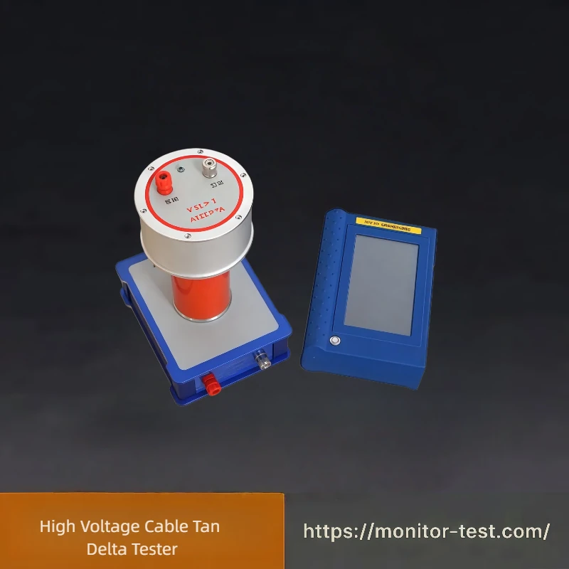
Tan delta (dissipation factor) measures the dielectric loss of capacitive insulation. On HV cable, motors and bushings, the HF-CH-209 high voltage cable tan delta tester works with an external high-voltage excitation source — a test transformer or a series resonance set — for both factory inspection and on-site insulation testing. Rising loss at a known voltage is the trend that matters; a single number in isolation rarely is.
It is worth keeping two different tan delta tests apart. Tan delta of transformer oil measures the loss of an oil sample in a test cell and belongs with oil quality testing, not with cable insulation — that is a separate instrument and a separate procedure, and HF supplies it as the HF-TC-629 tan delta test of transformer oil set. Cable tan delta is measured on the cable itself, at voltage.
Damped AC and partial discharge is the method for extruded MV cable, where PD activity in joints and terminations is the earliest available warning. The HF-CH-203 cable damped oscillating wave test system performs AC withstand voltage testing and partial discharge detection on medium-voltage cable and locates PD in cable bodies and joints, built to the IEC 60270 measurement standard. The HF-CH-202 OWTS system applies the same principle specifically to 35 kV MV cable, as an alternative to frequency-tuned series resonance withstand testing for handover and preventive testing programmes.
Identification and safe working
A large share of cable incidents are not electrical failures at all — they are a crew working on the wrong cable. Identification equipment exists to make that impossible, and on HV systems it is not a simple clamp-on job.
- Energised single-core cable at 35–500 kV — most single-core cables are grounded at one end, which defeats conventional identifiers. The HF-CH-225 live cable identification tester uses satellite time synchronisation to identify energised single-core cables under those conditions.
- De-energised cable in a bundle — the HF-CH-201 power cable identifier picks the target cable out of a bundle using closed-loop detection with qualitative and quantitative parameter judgement.
- Confirming the cable is dead before cutting — the HF-CH-220 cable voltage detector judges energised status with a handheld receiver and stethoscope sensor, and where a positive destructive confirmation is required, the HF-CH-219 high voltage cable spiking tool performs a remote or automatic puncture: an energised cable arcs, a de-energised one does not. It is a deliberately destructive safety method.
- Phase and sequence — the HF-CH-221 phase sequence tester works by clamp-type non-contact inductive measurement, without disconnecting terminals or touching live conductors, and the HF-CH-211 wireless high voltage phase detector covers contact and non-contact phase verification from 10 V to 550 kV.
Supporting equipment completes the set: the HF-CH-215 cable high voltage signal generator provides a 0–32 kV adjustable discharge with a 2 μF energy storage capacitor for triggering and testing; the HF-CH-214 cable fault simulation system lets a training centre or a calibration lab set up fault types, properties and distances on 10 kV three-core cable, so crews and instruments can be checked before they are needed; the HF-CH-224 mining cable marking machine handles cable management in mining and drilling applications; the HF-CH-222 mining cable fault detector addresses the harsher case of mining cable damage where conventional impulse methods damage the insulation further; the HF-CH-206 overhead line fault locator covers 6–35 kV overhead lines including grounding, short-circuit and arc-grounding defects; and the HF-CH-210 transmission line parameter tester measures the sequence impedances and capacitances that a cable or line model needs.
Monitoring instead of testing: watching a cable that stays in service
Offline testing answers the question at the moment of the test. Online monitoring answers it continuously, which matters for cables that cannot be taken out of service and for failure mechanisms that only appear under load or in bad weather.
- Partial discharge — the HF-C-201 cable partial discharge monitoring system combines HFCT, UHF and ultrasonic detection for continuous PD capture on medium and high voltage cable, with sheath circulating current and insulation variation as supporting channels and solar off-grid supply for sites without power.
- Sheath grounding current — the HF-C-202 cable sheath grounding current monitoring system watches the metallic sheath, which is where multi-point grounding, stolen grounding conductors and failed cross-bonding links show up — the conditions that quietly shorten cable life and reduce supply reliability.
- Temperature — the HF-C-203 cable temperature online monitoring system covers joints, trenches and branch boxes, where overheating is local and manual patrols miss it.
- Travelling-wave fault location — the HF-C-204 cable fault location monitoring system captures transient fault signals and latent insulation defects in service, so a fault is located from the record rather than by testing after the outage.
The choice between testing and monitoring is not either/or. A typical programme uses offline testing at handover and for periodic verification, and online monitoring on the circuits where an outage is expensive. Cable theft and accidental third-party damage sit outside both: that is a security problem, and it is covered separately in transformer cable cutting detection.
The standards that apply
- IEC 60270 defines partial discharge measurement itself — quantities, calibration and test circuits — and it is the reference behind PD testing equipment, including HV cable PD test sets.
- IEC 60885-3:2015 gives the PD test methods for lengths of extruded power cable. It is worth knowing its boundary: the standard does not cover measurements on installed cable systems, which is why on-site PD work refers back to IEC 60270 and to the manufacturer’s procedure instead.
- IEC 60502-1 and IEC 60502-2 specify construction, dimensions and test requirements for extruded-insulation power cable — 1 kV and 3 kV in Part 1, 6 kV to 30 kV in Part 2 (Um up to 36 kV).
- IEEE 400.2, the guide for field testing of shielded power cable systems using very low frequency (VLF, below 1 Hz), is the reference to follow when a VLF withstand or diagnostic test is specified on a shielded cable system.
Frequently asked questions
What is the difference between pre-location and pinpointing a cable fault? Pre-location measures the distance from the test end to the fault, typically from pulse or pulse-current reflections, and gives you a number. Pinpointing uses that number with an impulse source and an acoustic-magnetic or step-voltage detector to mark the exact position on the ground. A locator alone cannot tell you where to dig.
Why can a high-resistance cable fault not be located directly? Because the fault barely reflects the test pulse, so there is almost nothing for the instrument to measure. The standard approach is to convert it first — a burn-down unit applies high voltage and current to reduce the fault resistance until ordinary location methods can see it clearly.
Is cable tan delta the same as tan delta of transformer oil? No. Cable tan delta measures the dielectric loss of the cable insulation itself, at voltage, using an external high-voltage excitation source. Transformer oil tan delta measures the loss of an oil sample in a test cell and belongs with oil quality testing. They use different instruments and different procedures.
When should a cable be monitored online instead of tested offline? When the circuit cannot be taken out of service, when the failure mechanism is intermittent and only appears under load, or when the cost of an unplanned outage is high. Online PD and sheath-current monitoring capture conditions that a scheduled offline test will simply miss. Offline testing still has the advantage of full control over the applied voltage.
Why spike a cable instead of just testing it for voltage? Because a spiking tool gives the crew a positive, physical confirmation that the cable is de-energised: an energised cable arcs during the puncture. It is a remote or automatic operation precisely because it is destructive at the point of contact, and it is used where the consequence of cutting a live cable makes a second, independent check worthwhile.
If you are not sure which of these jobs you actually have, describe the symptom rather than the specification — what happened, whether the cable is in service, what the last test result was, and what insulation type and voltage level you are working on. The cable test instrument range covers fault location, diagnostics and identification, and the online cable monitoring range covers circuits that stay energised.