Leave your message

-
Leon Zhang sales consultant
-
Email: zxl635973785@gmail.com
-
Phone/WhatsApp/Wechat: +86 13655813266

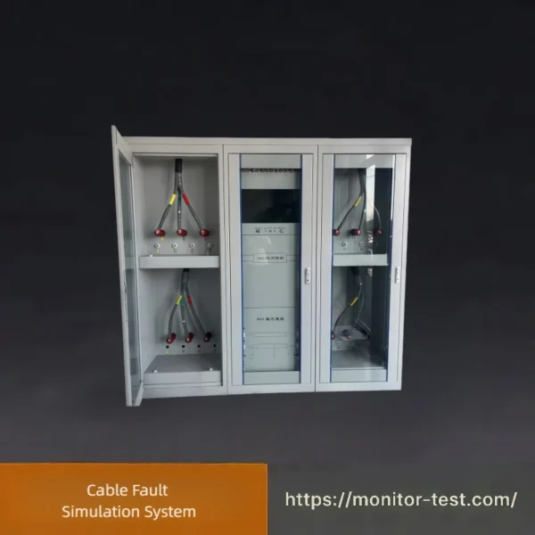
HF-CH-214 Cable Fault Simulation System
The Cable Fault Simulation System can reproduce diverse power cable faults including short circuit, open circuit, insulation aging and water tree defects. It is specially designed to calibrate, test and verify the accuracy and stability of all types of cable fault detection and positioning instruments in labs and factories.
Send your requirements, we will quote for you within 12 hours
This professional testing platform is built with ubiquitous power IoT technology and integrated multi-functional test modules. It supports flexible setup of fault types, properties and fault distances for 10kV three-core power cables. Widely adopted for cable fault testing skill training and performance calibration of various cable fault detection & locating devices in power industries, labs and equipment manufacturers.
Product Features
Adopting advanced ubiquitous electric Internet of Things technology and integrating diversified test modules, this device allows arbitrary configuration of fault types, fault characteristics and fault distances for 10kV three-core power cables. It is mainly applied to skill training on power cable fault testing and functional verification of testing instruments.
Technical Parameters
| Parameter Item | Specifications |
|---|---|
| Applicable Cable Voltage Level | 10 kV |
| Insulation Strength Index | No flashover or breakdown after applying 2500 V power frequency voltage for 1 minute; DC withstand voltage between high-voltage conductor core and ground wire exceeds 30 kV |
| System Composition | Integrated central control system, consisting of control cabinet and fault setting cabinet |
| Control Mode | Controlled by industrial personal computer or laptop |
| Fault Setting Method | Configured via background computer; response time ≤ 200 ms |
| Fault Types | Main insulation faults |
| Quantity of Main Insulation Fault Points | 3 fault points |
| Service Life | Trouble-free operation for 30,000 cycles |
| Main Insulation Fault Configuration | Freely switchable among high-resistance fault, low-resistance fault, flashover fault and healthy cable status |
| Healthy Condition | DC withstand voltage ≥ 30 kV; breakdown voltage ≥ 20 kV |
| High-resistance Fault | Breakdown voltage ≤ 10 kV; grounding resistance > 500 kΩ |
| Flashover Fault | Breakdown voltage ≤ 12 kV; grounding resistance > 200 MΩ |
| Low-resistance Fault | Grounding resistance < 200 Ω |
| Overall Control Cabinet Dimensions | 800×600×2100 mm |
| Installation Method | Installed at different positions on the same phase cable |
Operation Instructions for Cable Fault Simulation System
Pre-operation Inspection & Connection
Place the control cabinet and fault setting unit properly, connect power supply, communication cables and the tested 10kV three-core power cable securely. Check all wiring terminals to ensure tight connection without looseness.
Power On & System Startup
Switch on the main power supply. Launch the control software on industrial PC or laptop; wait for the whole system initialization and hardware self-check to complete normally.
Parameter & Fault Configuration
Enter the software background interface, select target fault point, then set required working status freely: healthy cable state, high-resistance fault, low-resistance fault or flashover fault. Customize fault electrical parameters as needed. The system will respond within 200ms after confirmation.
Carry Out Test & Calibration
Connect your cable fault detector to the cable under test. Run detection tests repeatedly to verify the locating accuracy, sensitivity and overall performance of the testing instrument under various fault conditions.
Switch Fault Conditions As Required
During testing, you can switch different fault types, adjust grounding resistance and breakdown voltage parameters anytime to simulate diverse on-site cable fault scenarios for skill training or equipment verification.
Shutdown Procedure
After all tests finish, restore the cable to intact healthy state first. Exit the control software safely, cut off system power supply, then disconnect all connecting wires and tidy up all accessories for storage.
FAQ | Cable Fault Simulation System
Q1: What is the main purpose of this cable fault simulation system?
A1: It is used to simulate various typical faults of 10kV three-core power cables. It can be applied for power worker cable fault testing skill training, as well as calibration and performance inspection of all kinds of cable fault locating and testing instruments.
Q2: Which voltage grade of cables does the system adapt to?
A2: It is specially designed for 10kV power cables, which is the most widely used distribution network cable in power systems.
Q3: How many fault points can this device set at the same time?
A3: It is equipped with 3 independent main insulation fault points installed on different positions of the same cable phase.
Q4: What types of cable faults can be simulated?
A4: Four switchable states are available: healthy intact cable, high-resistance fault, low-resistance fault and flashover fault.
Q5: What is the response speed when switching fault modes via software?
A5: Fault configuration is completed through computer background control, and the system response time is no more than 200ms, achieving rapid state switching.
Q6: What are the insulation withstand voltage standards of the equipment?
A6: It can withstand 2500V power frequency voltage for 1 minute without flashover or breakdown; the DC withstand voltage between high-voltage core and ground wire is higher than 30kV.
Q7: How long is the service life of the whole system?
A7: The system can realize trouble-free operation up to 30,000 working times with stable long-term operation performance.
Q8: What are the parameter standards for each fault mode?
- Healthy state: DC withstand voltage ≥30kV, breakdown voltage ≥20kV
- High-resistance fault: breakdown voltage ≤10kV, grounding resistance>500kΩ
- Flashover fault: breakdown voltage ≤12kV, grounding resistance>200MΩ
- Low-resistance fault: grounding resistance<200Ω
Q9: What devices can be used to control the system?
A9: Two control modes are optional: industrial control computer (IPC) or ordinary laptop computer.
Q10: What is the overall cabinet size and installation way?
A10: The dimension of the integrated control cabinet is 8006002100mm. Fault components are mounted on different positions of the same single-phase cable.
Q11: Can I adjust grounding resistance and breakdown voltage parameters arbitrarily?
A11: Yes. You can flexibly adjust relevant electrical parameters according to training and calibration demands to restore actual on-site cable fault conditions.
Q12: Is the operation complicated for new operators?
A12: The software interface is intuitive and user-friendly. Operators can quickly master fault setup, state switching and test operation after simple guidance.
Reviews
There are no reviews yet.