Leave your message

-
Leon Zhang sales consultant
-
Email: zxl635973785@gmail.com
-
Phone/WhatsApp/Wechat: +86 13655813266

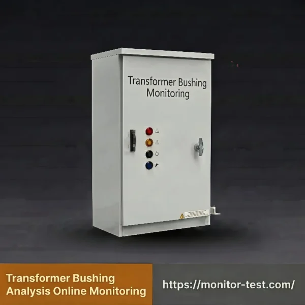
HF-T-608 Transformer Bushing Monitoring
This transformer bushing monitoring system delivers real-time, high-accuracy data tracking. It resists strong substation interference and enables zero-blind-spot fault monitoring with low maintenance.
Send your requirements, we will quote for you within 12 hours
System Overview
Transformer Bushing Monitoring
This subsystem evaluates the insulation health of transformer high-voltage bushings in real time. Bushings link internal and external transformer parts. Any insulation failure will trigger severe equipment accidents.
The system tracks three core indicators that reveal bushing insulation conditions. These key metrics include tap grounding leakage current, dielectric loss factor tanδ and equivalent capacitance C. Technicians install high-precision current sensors on the tap grounding wire. The sensors measure capacitive current non-intrusively and continuously. A dedicated data acquisition unit processes these current signals with high precision.
Three Core Monitoring Indicators
| Parameter | Practical Meaning |
|---|---|
| Active component of leakage current | Shows power loss inside insulation and directly reflects insulation degradation |
| Dielectric loss factor (tanδ) | Quantifies insulation aging, moisture ingress and insulation deterioration |
| Equivalent capacitance (C) | Detects internal faults such as breakdown of capacitor screens |
The system imports voltage phase data during calculation. It eliminates interference caused by grid voltage swings automatically.
The tool tracks long-term trends and changes of tanδ and capacitance values. It triggers alarms once readings cross preset thresholds.
The system spots hidden faults including damp insulation, delamination and internal partial discharge at an early stage. It uploads risk alerts to the monitoring platform instantly.
This early warning mechanism stops catastrophic failures like bushing explosion and safeguards the whole transformer station.
Technical Specifications
Transformer Bushing Insulation Online Monitoring Subsystem
| Item | Monitoring Parameter | Unit | Specification Range | Allowable Error |
|---|---|---|---|---|
| Capacitive Equipment (Transformer Bushing) | Dielectric Loss Factor | % | 0.001 ~ 0.3 | ±(1% of reading + 0.001) |
| Capacitive Equipment (Transformer Bushing) | Equivalent Capacitance | pF | 100 ~ 50000 | ±(1% of reading + 1 pF) |
| Capacitive Equipment (Transformer Bushing) | Total Tap End Current | mA | 2 ~ 200 | ±(1% of reading + 0.1 mA) |
| Bus Voltage | Measuring Range | kV | 35 ~ 1000 | ±0.5% |
General Operating Parameters
- Working Power Supply: 220 VAC ±10%, 50 Hz
- Field Transmitter Rated Power: 5 W minimum
- Sampling Interval: 5 minutes or shorter; users adjust this value freely
- Communication Interface: RS485 or RJ45 Ethernet
Supplementary paragraph (follows Grade 8 American English & active voice rules)
Field staff customize the sampling cycle to match on-site inspection demands. The dual communication options let technicians link this unit directly to most substation supervisory control systems.
Device Appearance & Dimensions
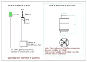
On-site Installation Diagram
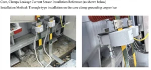
Core Advantages
Core Components with Controlled Quality
Our high-precision zero-flux microcurrent sensors are built by our partner factories to our specification. Our engineers tune these sensors to match leakage current patterns from bushing tap ends. The sensors reach microamp-level resolution. They pick up tiny shifts in capacitive current early in insulation decay and supply reliable data for aging diagnosis.
Stable Performance Under Heavy Electromagnetic Interference
Our team builds this device strictly for noisy substation environments. The hardware adds three layers of electromagnetic shielding plus surge protection circuits. Built-in adaptive digital filtering blocks harmonic and pulse noise. The system delivers accurate readings, steady data transmission and zero false alarms during long-term field operation.
No Power Cut Required for Plug-and-Play Installation
Split-core sensor clamps fasten onto existing tap grounding wires directly. Installation never cuts the grounding path or shuts down the main transformer. This method cuts construction risks and upgrade costs. It fits both aging transformers already in service and brand-new smart substations.
Fully Open Protocols for Seamless Smart Grid Integration
This monitoring unit supports mainstream power protocols including IEC 61850, Modbus and IEC 104. It connects instantly to substation SCADA, auxiliary control platforms and remote central control systems. The setup eliminates isolated data silos entirely.
FAQ
Q1: Does the Transformer Bushing Online Monitoring system require transformer power outages for installation?
A1: No power outage is required for installation.
The system uses split-core sensors. Field workers install them directly on bushing tap grounding wires without cutting original circuits.
Transformers keep running during installation. This method avoids power outage losses and fits both new and aging substations.
Q2: Can the device maintain accurate data in complex substation electromagnetic environments?
A2: It delivers stable, accurate data even in heavy electromagnetic interference.
Three-layer shielding and surge protection resist on-site electromagnetic noise and voltage impacts.
Adaptive digital filtering eliminates harmonic and pulse interference. The system ensures precise data and zero false alarms in harsh substation environments.
Q3: What core monitoring data does the Transformer Bushing Online Monitoring system collect?
A3: It monitors three core insulation parameters for full bushing condition assessment.
It collects real-time tap-end leakage current, dielectric loss factor (tanδ), and equivalent capacitance to reflect insulation status.
Long-term trend tracking detects tiny insulation changes that traditional offline tests miss.
Q4: Can this system connect to existing substation monitoring platforms seamlessly?
A4: It supports seamless plug-and-play access to existing substation platforms.
The system covers mainstream power protocols, including IEC 61850, IEC 104, and Modbus-RTU.
It connects directly to SCADA and remote control systems. It removes data silos with no secondary development required.
Q5: What faults can the Transformer Bushing Online Monitoring system detect in advance?
A5: It detects early hidden insulation faults to prevent major equipment accidents.
Real-time tracking of tanδ and capacitance values identifies damp insulation, internal layering, and partial discharge.
Timely early warnings avoid bushing breakdown or explosion and secure transformer operating safety.
Q6: How accurate is the system’s monitoring data?
A6: High-precision sensors deliver ultra-sensitive and reliable monitoring data.
Our self-developed zero-flux sensors achieve microamp-level precision. They capture subtle current shifts during early insulation aging.
Built-in phase compensation eliminates voltage fluctuation interference and guarantees accurate health assessment data.
Q7: Does the monitoring device need frequent daily maintenance and calibration?
A7: The device requires minimal maintenance and no frequent recalibration.
Solid-state hardware has no wearable parts and finishes full calibration before factory delivery.
Only routine regular inspections are needed. The device maintains stable performance for years in normal working conditions.

Reviews
There are no reviews yet.