

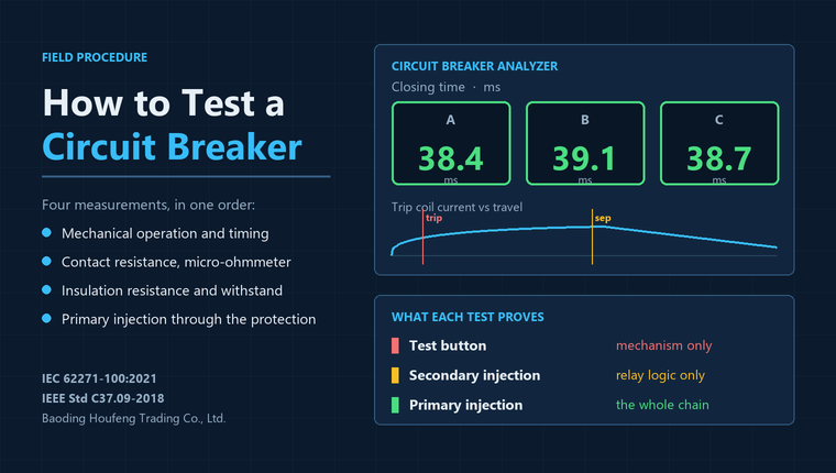
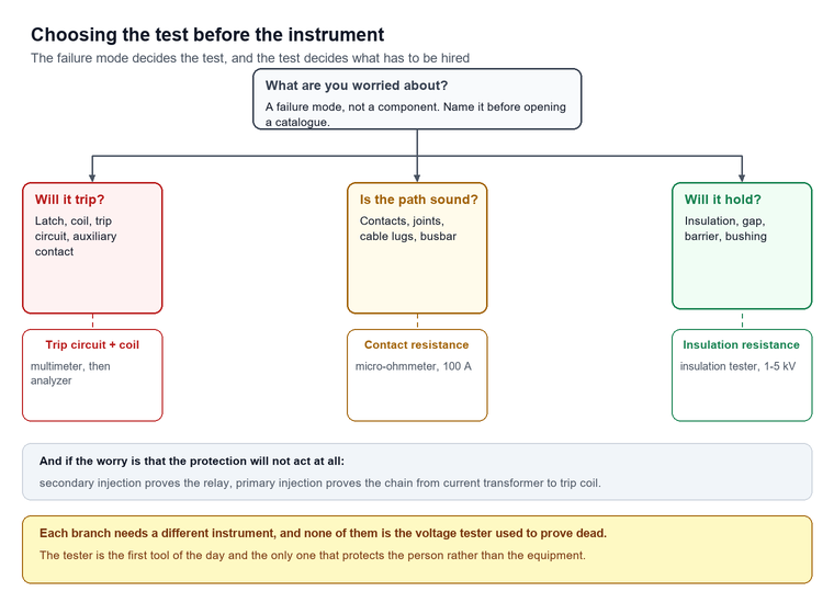
Knowing how to test a circuit breaker properly means separating four questions that are usually mixed together: will it trip when the protection asks it to, will it clear fault current when it does trip, will it interrupt without restriking, and will it survive the next twenty operations. Each question has its own test, its own instrument and its own acceptance figure, and a maintenance programme that runs only the first one leaves the other three unevaluated for the life of the switch.
Author: Leon Zhang — Power monitoring and testing equipment team, Baoding Houfeng Trading Co., Ltd., specifying switchgear test instruments for substations, plants and commissioning contractors
Technical review: this guide passed editorial review and was checked against IEC 62271-100:2021, IEC 60947-2:2016 and IEEE Std C37.09-2018 before publication
Last updated: 20 October 2026
Key takeaways
- Four tests, four questions. Mechanical operation proves the mechanism moves, contact resistance proves the current path is sound, insulation resistance and withstand prove the dielectric is intact, and primary injection proves the protection and the breaker act together. Skipping any one leaves a specific failure mode untested.
- The circuit breaker test button on a moulded case breaker proves almost nothing. It mechanically latches the trip bar, which confirms the mechanism is free but exercises neither the current sensing element nor the contacts, and a breaker that trips on the button can still fail to trip on a real overload, because the button exercises none of the current path that the overload has to pass through.
- Timing is measured against the breaker’s own type test record, not against a generic limit. A 40 ms opening time is excellent for one family and out of tolerance for another, and the only defensible comparison is with the curve published for that model.
- Contact resistance is a trend, not a pass-or-fail number. A 45 µΩ reading means nothing alone; the same pole reading 45 µΩ three years ago and 68 µΩ this year means the contact is eroding and the next test will decide whether it is replaced.
- A voltage tester for circuit breaker work confirms one thing only, that the point is dead. It is a safety instrument, not a diagnostic one, and a reading of zero volts is a claim about the tester and its proving unit as much as about the circuit.
- Testing without power is possible and useful, but it tests less. Mechanical timing, contact resistance, insulation and the trip circuit can all be verified with the breaker isolated, which is why most of the programme lives there; the parts that need current cannot be moved.
Introduction
A circuit breaker is the one component in a switchboard that is expected to work exactly once after years of doing nothing, and the test programme exists to make that single operation predictable. The work is unglamorous, it happens in outage windows, and the temptation to run the one test that fits the available time is what turns a maintenance programme into a formality.
This step-by-step guide follows the order a field engineer actually works in: isolate and prove dead, inspect, then measure the mechanism, the contacts and the insulation, then prove the protection operates the breaker, then record what was found in a form that survives an audit. Each step names the instrument, the acceptance figure and the failure it is designed to catch, and the closing sections cover what can be done on a de-energised board, where these tests stop being conclusive, and how to choose the instruments for a programme rather than for a single job.
Isolate, prove dead and lock off
Every test in this guide begins with the same three actions in the same order, because the first measurement of the day is also the one with the worst consequences if it is wrong. Isolate the circuit, prove the tester on a known live source, test the conductors, then prove the tester again, and only after that touch anything.
A proving unit is a source of known voltage used to check that the tester responds before and after the measurement, and it is not an accessory. A voltage tester that has failed silently reads zero on a live conductor with the same confidence as on a dead one, and the only way to distinguish the two is to check the instrument immediately before and immediately after the measurement. Many two-pole voltage testers have a self-test button that checks the internal circuit and the battery; that is necessary and not sufficient, because it does not prove the probe tips and the lead are intact.
| Step | Action | What it proves | What it does not prove |
|---|---|---|---|
| 1 | Identify and open the isolating device, then lock and tag | The intended source is disconnected | That no back-feed exists |
| 2 | Prove the tester on a known live source or proving unit | The tester responds when it should | That the leads and tips are sound |
| 3 | Test all conductors, phase to phase and phase to earth | Which conductors are dead | That the circuit cannot be re-energised |
| 4 | Prove the tester again on the same source | It survived the measurement | Nothing further |
| 5 | Apply earths and short-circuits where the procedure requires | The circuit is held at earth potential | That the breaker mechanism is sound |
Choosing a voltage tester for circuit breaker work
A voltage tester for circuit breaker work has to satisfy three requirements that a multimeter does not. It has to be rated for the highest voltage present, with a CAT rating that matches the location rather than the nominal system voltage; it has to indicate presence and absence without needing to be switched on; and it has to give a clear indication in bright sunlight and through a mask, because the person holding it is often looking up at a busbar.
The CAT rating is the specification most often misread. A 1000 V CAT III tester used on a 400 V board at the origin of an installation, where the prospective fault current is high and the transient energy is large, is being used outside its rating even though the working voltage is well within it. The category describes the transient environment, and the correct choice for a substation secondary circuit is CAT IV, not CAT III.
Testing without power
Being able to test how to test a circuit breaker without power is what makes a maintenance programme practical: the board can be worked on during a planned outage, by one engineer, with instruments that fit in a case, and no primary current needs to be generated. In that condition the mechanism, the contacts, the insulation, the auxiliary contacts and the trip coil circuit can all be checked.
What cannot be checked without current is the current-sensing path: the protection relay’s measurement, the current transformers, the wiring between them, and the breaker’s ability to interrupt. Those require either primary injection at the actual current or a secondary injection into the relay with the trip circuit live, and both need the circuit arranged for it.
Step 1: visual and mechanical inspection
A visual inspection finds a third of the faults that a test programme reports, and it costs twenty minutes. The work is to look for what the last person left behind, and for the signs that the breaker has been doing something other than sitting closed since the last visit.
Start with the enclosure and the arc path. Look for soot or tracking marks on the barriers, discoloured paint around the arc chutes and any smell of burnt insulation, which usually indicates a restrike rather than a normal interruption. Look at the cable terminations for discolouration at the lug, which is the first visible sign of a loose connection heating under load.
Then the mechanism. Check that the spring charge indicator shows the state the drawing expects, that the closing and opening coils are seated and their plugs latched, and that the auxiliary switch is in the position that matches the main contact. A breaker whose auxiliary switch has slipped half a position will pass every electrical test and still fail to signal its state to the protection scheme.
| Item | Frequency | What it catches |
|---|---|---|
| Enclosure and barriers | Every visit | Tracking, soot, water ingress |
| Cable terminations | Every visit | Loose lugs heating under load |
| Mechanism and spring charge | Every visit | Incomplete charge, worn linkage |
| Auxiliary switch alignment | Every visit | State indication errors to the protection scheme |
What the inspection is looking for
| Observation | Likely cause | Test that confirms it |
|---|---|---|
| Soot on barriers or around the arc chute | A restrike or repeated interruption at high current | Insulation resistance and a contact-resistance trend |
| Discoloured cable lug | Loose termination heating under load | Contact resistance across the joint, plus a thermal scan |
| Spring charge indicator inconsistent with the drawing | Mechanism not fully charged, or an incorrect indicator | Timing test on the closing operation |
| Auxiliary switch between positions | Linkage slipped or worn | Continuity check in both main positions |
| Oil level or colour changed on an oil breaker | Arcing by-products, or a leak | Oil dielectric strength and moisture |
| Condensation or water marks inside the enclosure | Heater failed or the gasket is perished | Insulation resistance, then the heater circuit |
Step 2: contact resistance with a micro-ohmmeter
Contact resistance is the resistance of the current path through the closed breaker, from one terminal to the other,, and it is measured with a four-wire instrument that injects a defined direct current and reads the voltage across the contacts. The four-wire arrangement removes the lead resistance from the result, which matters when the quantity being measured is a few tens of microhms.
The test current matters as much as the instrument. A contact resistance measured at 10 A and one measured at 100 A can differ, because the contact spots and any surface film behave differently at higher current density, and the value that corresponds to service is the one measured at a current in the range the manufacturer specifies. Most switchgear standards and type test records quote the value at 100 A or above, and a handheld micro-ohmmeter rated for that current is the instrument the value assumes.
| What is measured | Typical instrument | Test current | Typical new value |
|---|---|---|---|
| Vacuum interrupter, per pole | Micro-ohmmeter, four-wire | 100 A or more | 20 to 60 µΩ |
| SF6 interrupter, per pole | Micro-ohmmeter, four-wire | 100 A or more | 30 to 80 µΩ |
| Air circuit breaker, per pole | Micro-ohmmeter, four-wire | 100 A or more | 40 to 100 µΩ |
| Moulded case breaker, per pole | Micro-ohmmeter, four-wire | 10 to 100 A | 100 to 500 µΩ |
| Busbar joint and cable lug | Micro-ohmmeter, four-wire | 100 A or more | Compared with a sister joint |
Reading a contact resistance result
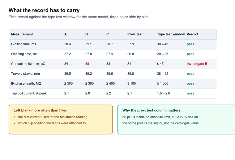
The number to compare is not a limit but the same pole’s previous value, normalised where possible for the test current. A rise of more than about 33% on the same pole, or a spread of more than 33% between the three poles of the same breaker, is the signal to investigate (NETA acceptance testing specifications, 2023), and either can be caused by a contact that is eroding, a joint that has loosened or a test lead that was clipped to a painted surface.
On a survey of commissioning records
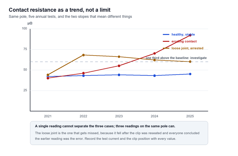
On a survey of commissioning records from medium-voltage substations, the single largest cause of a failed contact resistance test was not the breaker but the clip. Leads clipped to a painted cross-member, to a plated washer already carrying current, or to the earthing bar rather than the bushing stud produced readings that disagreed with the previous report by a factor of two, and in each case the breaker was fine.
Two errors recur. The first is measuring through the earthing switch or the earth bar, which puts a parallel path in the measurement and gives a reading lower than the contact resistance. The second is testing a vacuum bottle that has been sitting in a humid enclosure and reading a high value from a surface film, which usually falls after a few operations; a value that does not fall after three operations is a real finding.
Step 3: insulation resistance and withstand
Insulation resistance is measured between the live parts and earth, and between the poles with the breaker open, using a megohmmeter at a direct voltage of 500 V or 1000 V for low-voltage equipment and considerably more for medium voltage. The measurement is a trend as much as a number, and the useful comparison is against the previous test on the same breaker and against the other two poles.
The value that matters for a medium-voltage breaker is usually quoted in the hundreds of megohms or in gigohms, and a reading in single megohms after a humidity change is not necessarily a fault. Moisture on the surface of a barrier can pull a healthy breaker down by two orders of magnitude, and the way to separate a surface problem from a bulk problem is to repeat the test after cleaning and drying, or to compare the reading with the guard terminal connected. The trigger for investigation is a fall of 50% or more against the previous test on the same breaker, because insulation breakdown is a trend long before it is an absolute value (NETA acceptance testing specifications, 2023).
| Test | Instrument | Voltage applied | Where it is applied | Reading that triggers action |
|---|---|---|---|---|
| Insulation resistance, LV | Insulation tester | 500 V DC | Phase to earth, pole to pole | Below 1 MΩ on a 400 V circuit |
| Insulation resistance, MV | Insulation tester | 1000 to 5000 V DC | Phase to earth, pole to pole | Below the manufacturer’s floor, or a fall of more than half |
| Polarisation index | Insulation tester with timed readings | Same | Same | Ratio below 2 on a machine winding |
| Power-frequency withstand | AC test set | Per IEC 62271-1:2017 | Phase to earth and across the open gap | Any breakdown |
| Dielectric loss on bushings | Tan delta set | 10 kV | Bushing insulation | Rising trend against the previous test |
Where withstand testing stops and risk starts
A power-frequency withstand test on a medium-voltage breaker is a destructive test in the sense that it either passes or it damages something, and it is carried out at a voltage well above the working voltage, typically at four-fifths of the type test value for a routine check. It is worth doing on a new installation, on a repaired interrupter, and after a fault that may have left tracking on a barrier; it is not worth repeating annually on a healthy breaker that has been sitting closed.
The trade-off is real and is worth stating plainly. Each withstand test puts the insulation under a stress it does not see in service, and repeated testing of a healthy breaker ages the very insulation it is meant to prove. IEC 62271-1:2017 sets the routine test voltage, and a programme that runs the test every year on every breaker is spending insulation life to answer a question that contact resistance and insulation resistance already answered.
Step 4: timing the mechanism: how to test a circuit breaker's speed
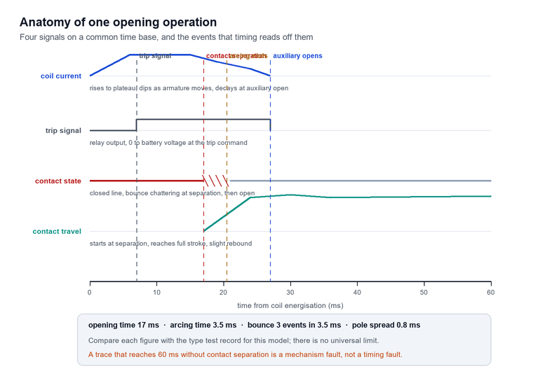
Timing is where most of the diagnostic value sits, and a circuit breaker analyzer records the coil current, the main contact state, the travel of the moving contact and the time of each event in one operation. That single record answers the questions that matter most for reliability: how long the breaker takes to open, how far apart the three poles operate, whether the contact bounces, and whether the mechanism is binding.
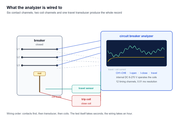
The instrument is connected to the main contact terminals, to the trip and close coils, and to a travel transducer clamped to the operating rod.
It then operates the breaker itself, through its internal power supply, and records the whole event at a sample rate high enough to resolve a bounce of a few hundred microseconds. The result is a set of traces that a reviewer can read without having been present.
The parameters that matter
| Parameter | What it shows | Typical acceptance basis |
|---|---|---|
| Opening time | Interval from coil energisation to contact separation | The type test record for that model, usually a window of a few milliseconds |
| Closing time | Interval from close coil energisation to contact touch | The type test record, plus the closing resistor sequence where fitted |
| Pole discrepancy | Difference between the fastest and slowest pole | Manufacturer’s limit; a few milliseconds on a generator breaker |
| Bounce time and count | Chattering after first touch | Type test record, typically a limit in milliseconds |
| Contact travel and overtravel | Whether the mechanism reaches its designed position | The drawing dimensions for that model |
| Coil current trace | Whether the coil is being driven correctly | Shape against the reference trace, not a single value |
Reading the coil current trace
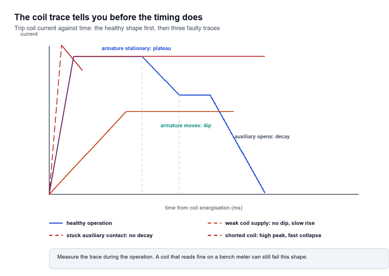
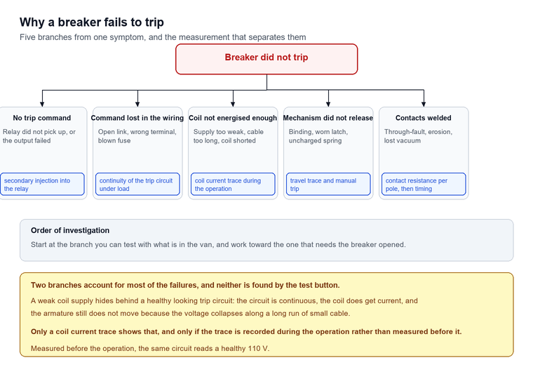
The coil current trace is the most informative single channel and the least understood. A healthy trip coil produces a current that rises to a plateau, holds while the armature is stationary, then dips or rises as the armature moves and the magnetic circuit changes, and finally decays when the auxiliary contact breaks the circuit. The timing of the dip is the moment the mechanism started to move, and the point at which the current falls to zero is the moment the auxiliary contact opened.
Three faults show up in that trace before they show up anywhere else. A trace that never reaches its plateau indicates a supply that is too weak, too far away or too resistive, which is the failure mode that leaves a breaker unable to trip after a long cable run. A trace that stays on the plateau and never decays indicates an auxiliary contact that failed to open, which will burn the coil. A trace with an abnormally short plateau and an early decay indicates a coil that is partially shorted or a mechanism that is already part-way through its travel.
Step 5: proving the protection operates the breaker
Primary current injection is the only test that proves the whole chain at once: the current transformer, the wiring to the relay, the relay’s measurement and logic, the trip circuit and the breaker mechanism. It is also the slowest test in the programme, because it requires a high-current source, the current transformers to be in circuit and the breaker to be free to operate.
The test is carried out with a primary current injection set by injecting current into the primary of the current transformer at a value above the relay setting, and observing whether the breaker opens within the expected time. A three-phase set is needed for anything that involves negative sequence or earth fault elements, and the injection has to be at the correct phase angle where the element is directional.
| Test in the sequence, for how to test a circuit breaker | What it proves | Instrument | Needs primary current |
|---|---|---|---|
| Mechanical timing | Mechanism and contacts operate correctly | Circuit breaker analyzer | No |
| Contact resistance | Current path is sound | Micro-ohmmeter | No |
| Insulation resistance | Dielectric is intact | Insulation tester | No |
| Secondary injection | Relay measures and decides correctly | Relay test set | No, but the trip circuit must be live |
| Primary injection | The complete chain trips at the setting | Primary current injection set | Yes |
| Trip circuit supervision | The trip path is continuous | Multimeter or a dedicated monitor | No |
Why secondary injection is not enough on its own
Why secondary injection is not enough on its own
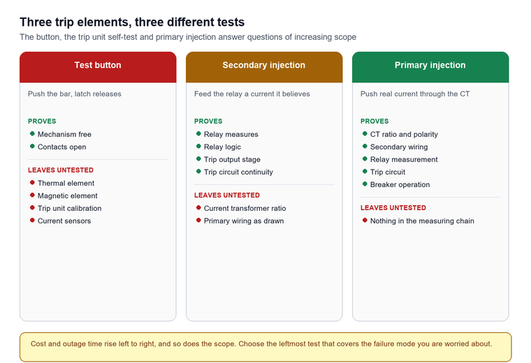
Secondary injection proves the relay, and it does so thoroughly, with a precision that primary injection cannot match. What it does not prove is everything between the relay and the fault: a current transformer with a shorted secondary, a wire landed on the wrong terminal, a ratio that does not match the drawing, or a test link left open after the last visit.
The two tests are complementary and should be scheduled together on a new installation and on any circuit that has been rewired. On a routine maintenance visit, secondary injection plus a contact resistance and timing test covers the failure modes that actually occur, and primary injection is reserved for new commissioning, post-fault investigation and the periodic verification that the ratios are still as drawn.
Step 6: the test button and what it actually proves
The circuit breaker test button on a moulded case or miniature circuit breaker is a mechanical device that pushes the trip bar directly, and pressing it confirms that the latch is free and the mechanism will open when the bar moves. That is all it confirms. It does not exercise the thermal element, the magnetic element, the electronic trip unit or the contacts, and a breaker that trips on the button can still be unable to trip on a real overload.
| Device | What the button tests | What it leaves untested |
|---|---|---|
| Miniature circuit breaker | The latch releases and the contacts open | The thermal and magnetic trip elements |
| Moulded case breaker with thermal-magnetic trip | The latch and the mechanism | The bimetal calibration and the magnetic threshold |
| Moulded case breaker with electronic trip | The latch, and on some models the trip unit’s self-test | The current sensors and the actual trip thresholds |
| Air circuit breaker with a test position | The mechanism, with the main contacts isolated | The primary current path |
| Residual current device | The trip mechanism and, on some models, part of the sensing circuit | The full leakage detection at the rated residual current |
The correct use of the button is as a monthly functional check of the mechanism between the annual electrical tests, and it should be recorded as such rather than being presented as evidence that the breaker is calibrated. For an electronic trip unit, the manufacturer’s test set or a secondary injection into the trip unit is the test that proves the protection settings, and the button proves only that the output stage can operate the latch.
Recording the result and comparing it with the type test
A test that is not recorded to a comparable form cannot be trended, and a programme without trends reduces every reading to a pass or a fail against a number that may not apply to the breaker in front of you. The record has to carry the conditions, not just the number.
What belongs on the sheet: the breaker model and serial number, the instrument and its calibration due date, the test current for the contact resistance, the ambient temperature and humidity, the supply voltage at the coil during the timing test, and the previous values for the same poles. Those five conditions explain almost every disagreement between two test reports on the same breaker.
Limitations and boundaries
Limitations and boundaries
A test programme looks more complete than it is, and five limits bound what these measurements can claim.
The first is that a mechanical timing test at ambient temperature does not reproduce a fault interruption. A breaker that opens in 38 ms at 20 °C in still air is being asked to open in a fraction of that time under a fault, with an arc that heats the gas or the vacuum gap to thousands of degrees, and the mechanism’s behaviour in that regime is established by type test rather than by field measurement.
The second is that contact resistance cannot see a contact that is about to weld. A vacuum interrupter with a partially eroded contact can read perfectly well until the moment it fails to interrupt, and the trend only helps if the erosion is gradual and the breaker has been tested often enough to establish a slope.
The third is cost and downtime. A full programme, with primary injection, withstand testing and timing on every breaker, needs an outage per board, a specialist crew and a set of instruments that cost more than the breakers on a small site. For a distribution board with twenty moulded case breakers, the practical programme is a sample, and the sampling logic has to be written down and defensible.
The fourth is that the instruments need calibrating, and an out-of-calibration analyzer produces numbers with the same confidence as a calibrated one. A programme that does not track calibration due dates is testing the instrument’s drift rather than the breaker.
The fifth is that none of these tests evaluates the protection settings against the fault level. A breaker and relay that both operate correctly, at a setting that is wrong for the system, will pass every test in this guide and still fail to clear a fault. The settings review is a separate exercise, done on paper and in software, and it is the one step with no instrument attached.
Frequently asked questions
Frequently asked questions
These are the questions that come up most often when a test programme is being set up or when a result does not match expectation. Each answer stands on its own.
What is the fastest way to learn how to test a circuit breaker?
Start with the two tests that need nothing but a de-energised board, then add timing. Partly, A multimeter confirms continuity of the contacts, the state of the auxiliary switch, the resistance of a coil and the presence of voltage, and those checks are useful before any instrument is unpacked. It cannot measure contact resistance in microhms, cannot time an operation, and cannot apply the voltage needed to establish insulation condition, so it is a preparatory tool rather than a test instrument.
How do I test a circuit breaker without power?
Isolate and prove dead, then run the tests that do not need current: insulation resistance, contact resistance with a micro-ohmmeter, and a mechanical timing test driven by the analyzer’s own supply. The analyzer also operates the coils from its internal DC source, so the trip and close circuits can be exercised on a de-energised board with the breaker racked out, provided the procedure permits it.
What does the test button actually prove?
It proves the latch is free and the mechanism will open when the trip bar moves. It does not test the thermal element, the magnetic element, the electronic trip unit or the contacts, so a breaker that trips on the button can still fail to trip on an overload. Use it as a monthly mechanism check and keep the electrical tests separate.
Why does contact resistance change between tests?
Three causes, in order of frequency: the test current was different, the leads were clipped to a different point, or the contact really has changed. Surface film on a vacuum bottle that has been idle in a humid enclosure can raise the reading by tens of microhms and usually clears after a few operations. A reading that stays high after three operations is a real finding.
How long should a breaker take to open?
There is no universal answer, which is why the type test record for that model is the only defensible reference. A typical medium-voltage vacuum breaker opens in 30 to 60 ms from coil energisation, a generator breaker is faster, and an air circuit breaker slower. Compare against the same model’s published window and against the previous test on the same pole, not against a number remembered from another site.
Do I need primary injection if I have already done secondary injection?
On a new installation, yes, because it is the only test that proves the current transformer ratio and the wiring as well as the relay. On routine maintenance, secondary injection plus contact resistance and timing covers the failures that actually occur, and primary injection is reserved for commissioning, post-fault work and periodic verification that nothing has been rewired.
What is the correct test voltage for insulation resistance?
For a 400 V circuit, 500 V DC. For medium-voltage switchgear, 1000 to 5000 V DC depending on the rated voltage and on what the manufacturer permits. The voltage has to be high enough to reveal a weakness and low enough not to stress healthy insulation, and the manufacturer’s manual takes precedence over a generic table.
Conclusion
Knowing how to test a circuit breaker is really knowing which four measurements to run, in what order, and a programme is those four measurements taken in a fixed sequence, and the value comes from the order rather than from any single instrument. Prove dead, inspect, measure the contacts, measure the insulation, time the mechanism, then prove the protection operates the breaker. A programme that runs only the last step, or only the button, is confirming that the breaker still exists.
For a team setting up a programme, the practical sequence is to list the breakers by type and voltage, decide which of the four tests each one needs and how often, then buy the instruments in the order that removes the most risk per unit of cost: a micro-ohmmeter and an insulation tester first, a analyzer next, and primary injection shared between sites rather than bought per site.
Baoding Houfeng supplies the instruments that carry a ground resistance tester programme as well as this one. The units sit under the switchgear tester category page, with individual units on the breaker timing instrument, the mechanical characteristic analyzer, the handheld contact resistance tester and the primary current injection set pages. For the insulation side of the same visit, the insulation resistance test guide covers the megohmmeter and the withstand tests, and the protection relay testing equipment guide covers the relay side of the chain that ends at the trip coil. Company background is on the about us page. For a board that mixes moulded case breakers with one medium-voltage incomer, contact us with the breaker list, the voltages and the outage window, and we will tell you which combination of instruments covers the programme.
References and technical sources
- IEC 62271-100:2021, High-voltage switchgear and controlgear — Part 100: Alternating-current circuit-breakers, International Electrotechnical Commission, 2021, which defines the type tests, the rated operating sequence and the mechanical endurance classes referenced throughout this guide. webstore.iec.ch
- IEC 62271-1:2017, High-voltage switchgear and controlgear — Part 1: Common specifications for alternating current switchgear and controlgear, which sets the power-frequency withstand voltages applied in the routine test. webstore.iec.ch
- IEC 60947-2:2016, Low-voltage switchgear and controlgear — Part 2: Circuit-breakers, which defines the test sequence and the marking requirements for moulded case and air circuit breakers. webstore.iec.ch
- IEEE Std C37.09-2018, IEEE Standard Test Procedures for AC High-Voltage Circuit Breakers with Rated Maximum Voltage Above 1000 V, IEEE Standards Association, 2018, which sets out the design and production test procedures including timing and contact resistance measurement. standards.ieee.org
- IEEE Std C37.06-2018, IEEE Standard for AC High-Voltage Circuit Breakers Rated on a Symmetrical Current Basis — Preferred Ratings and Related Required Capabilities, which tabulates the rated interrupting times against which field timing is compared. standards.ieee.org
- NETA, Acceptance Testing Specifications for Electrical Power Equipment and Systems, InterNational Electrical Testing Association, which sets the field acceptance values for contact resistance, insulation resistance and timing used by commissioning contractors in North America. netaworld.org
- U.S. Department of Energy, Electrical Safety Handbook, which covers the isolation, proving-dead and lock-off procedure followed in the first step of this guide. energy.gov