

Switchgear monitoring is the online condition-monitoring set for a switchgear bay that keeps the temperature, partial discharge and SF6 density under observation between manual inspections, so a developing failure is caught before the bay is opened, and it logs the baseline for later comparison.
This guide treats switchgear monitoring as a decision system rather than a sensor catalogue. It covers which three channels to trust, how the channels are wired to the analyzer and SCADA gateway, and how the result is judged against a baseline before it is fed into a maintenance plan.
Key Takeaways
- A condition monitoring system that only logs one channel misses the failure that develops; a unit combining temperature, partial discharge and SF6 density sees the whole picture of a degrading bay.
- The baseline is the first thing to set: every later alarm is compared against the commissioning baseline, not an absolute number, because a stable reading at a high value is different from a reading that has doubled in two months.
- The temperature channel is the cheapest first step but lags a developing arc by days; a partial discharge signal on the busbar lead arrives earlier and is the channel most monitors skip because it is noisy under full system voltage.
- The SF6 density relay catches a sealed medium failing between switches, because the density falls before any error is visible in the temperature or discharge trend.
- A condition monitoring system must match the bay’s construction and the site’s data path: a local-only monitor is a box nobody reads, while an IEC 60870-5-104 link feeds the control room daily instead of a local display read once a year.
Busbar temperature monitoring
The practice of busbar temperature monitoring is the first channel most switchgear condition monitoring systems choose because the sensor is simple and the gain is immediate, with a winding and top-oil sensor feeding two numbers that predict overload and cooling failure. The monitoring adds trending that a dial gauge cannot show, and it pairs that trend with the load schedule to catch a cooling fan that has failed while the oil still looks normal.
The value of temperature alone is limited because heat is a late signal. A developing turn-to-turn fault can raise gas for weeks before the top-oil temperature moves a degree, so busbar temperature monitoring should be paired with the partial discharge channel rather than trusted on its own.
Busbar temperature monitoring is the practice of recording busbar and top-oil temperature so the loading can be matched to the cooling state of the bay.
Switchgear partial discharge monitoring
The partial discharge signal is part of the condition monitoring system, and the practice of switchgear partial discharge monitoring is the channel that catches an arcing fault before the bay is opened, because the partial discharge signal on the busbar lead appears a few seconds before the arc reaches the breaker’s contacts. The signal is noisy under full system voltage, so the monitoring system holds a baseline and reads the trend against it rather than judging the isolated number.
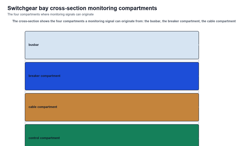
The partial discharge signal is read with the switchgear internal section in mind: the arcs can start in the busbar, in a joint or in a breaker compartment, or on the cable landing. A system that only reports the discharge number, and not the phase-resolved pattern, can read the different sources as the same event.
sf6 density relay monitoring
The practice of sf6 density relay monitoring is the channel that catches a sealed medium failing between switches, because the SF6 density falls before any gas error is visible in the temperature or discharge trend. The density is read from a dedicated relay on the switchgear gas pressure line, and the relay can report the density against the declared lower limit directly into the monitoring system.
The sf6 density relay matters most where the switchgear uses a sealed gas medium, because a bay that leaks its medium loses its containment and its dielectric strength before the operator notices the temperature rise. A system that omits the density channel will miss that loss, and the alarm that follows it comes too late. A switchgear monitoring system that omits this channel will miss the medium loss and the alarm comes too late.
Parameters compared across the channels
Channel | Purpose | Signal | Best for
| — | — | — | — |
|---|
Condition monitoring channel | Condition baseline | Winding and top-oil temperature | Load and cooling state Temperature plus partial discharge | Early failure warning | Temperature plus discharge signal | Arc before the bay is opened Temperature plus partial discharge plus SF6 density | Full condition picture | Three channels together | Degrading bay before an outage
System wiring for the monitoring system
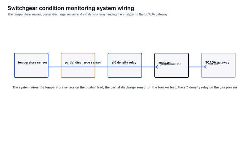
A monitoring system is wired so that the sensor, the analyzer and the gateway read the three channels in one pass, because the trend only counts when all three are measured under the same conditions. The wiring places the busbar temperature sensor on the busbar lead, the partial discharge sensor on the busbar or breaker lead, and the sf6 density relay on the gas pressure line, all feeding the analyzer that holds the baseline and reads the trend against it.
The system links the analyzer to the SCADA gateway for the site, so the control room can see the three channels daily instead of a local display read once a year. A local-only monitoring box is a valuable box that nobody reads.
Temperature alarm bands
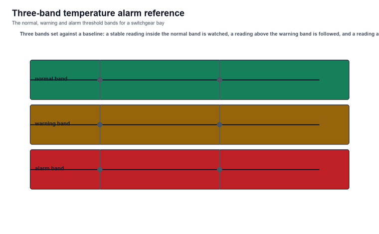
The alarm is set against a baseline band rather than an absolute level. A bay that sits at a high but stable temperature for a year is not the same as a bay whose temperature has risen over the last month, even if the two end at the same number. Three bands are used so the alarm fires on the change, and the trend is read against the slope of the normal band over the last maintenance interval.
Temperature threshold scale
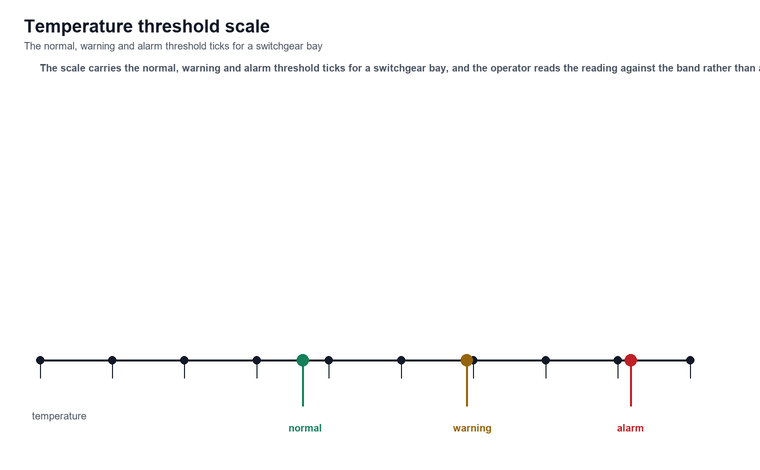
The temperature threshold scale is the number a maintenance plan is built on, because the threshold is set from the cooling rating and the site load rather than from a single reading. A switchgear monitoring threshold scale therefore carries the normal band, the warning band and the alarm band with tick marks, and the operator reads the reading against the band rather than against the number.
How a switchgear condition system fits the switchgear picture
The condition monitoring system is the set that fits the switchgear condition picture between manual inspections, and it answers a different question from a switchgear type test: what is the bay doing right now, under load, rather than whether the bay passed a factory test.
A switchgear monitoring result only counts when the three channels are measured under the same conditions and against the baseline, because a stable high temperature is different from a temperature that has risen, and a stable discharge is different from a discharge that has spiked.
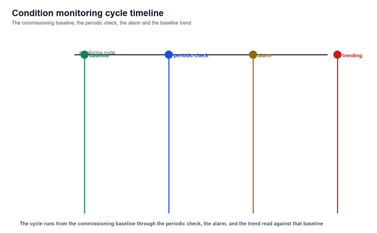
The monitoring cycle runs from the commissioning baseline through the periodic check, to the alarm, and to the trend read against the baseline. A switchgear monitoring result turns a scheduled teardown into a condition-based decision.
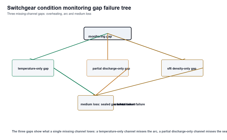
The monitoring also distinguishes the failure modes the three channels catch. Overheating caught by temperature shows a cooling or contact failure; an arc seen by partial discharge shows a contact or dielectric failure; and a falling sf6 density shows a medium failure in the sealed system. The three together give a switchgear monitoring condition report that tells the crew where to act, whether it is a cooling correction, a contact locate or a medium replacement.
Limitations and Boundaries
Three boundaries are worth stating before a switchgear monitor is bought, and each limits what the reading can claim even when the sensor is working and the numbers are clean.
First, the partial discharge signal on a live switchgear is a screening signal rather than a measurement of the discharge itself, because the background noise on the bus and the busbar voltage set the floor, and IEC 60270:2025 defines the charge-based discharge measurement that applies to the offline reading rather than to the online trend. An online discharge number is a trend built on the same physics, and it is not a substitute for the offline measurement.
Second, the temperature channel lags the arc by days. A developing turn-to-turn fault can raise the top-oil temperature only after the arc and gas have already risen, so busbar temperature monitoring alone is a late signal and must be paired with the partial discharge and sf6 density channels for the arc to be caught early.
Third, a monitor with no baseline produces a stream of numbers with no decision attached to them. A condition monitoring system installed on a bay with no commissioning reference reports readings that cannot be compared and are not useful until the baseline is set.
FAQ
What three channels should a switchgear condition system track?
A switchgear condition monitoring system should track the busbar temperature, the partial discharge signal and the sf6 density, because each channel answers a different question and together they show the whole condition of the bay.
Why must the baseline be set before the readings are judged?
The baseline is set at commissioning or at the last manual inspection, because every alarm is compared against it: a stable reading at a high value is different from a reading that has doubled in two months, and without the baseline a monitoring system reports numbers with no decision attached to them.
Can a temperature-only channel catch a developing arc?
A temperature-only switchgear condition channel is a late signal. It catches a cooling failure or a load rise before the arc shows, but it does not see the partial discharge or the sf6 density that arrive first, so it must be paired with the partial discharge and sf6 channels for the arc to be caught early.
Does a live partial discharge reading condemn the bay?
A live partial discharge reading on a switchgear is a screening number rather than a condemn measurement. It is used for trending, and a confirm decision still requires the offline discharge measurement defined by IEC 60270:2025.
Does the sf6 density relay matter for a non-gas switchgear bay?
The sf6 density relay matters for a switchgear bay that uses a sealed gas medium, because the density falls before the temperature or discharge trend shows the medium loss. For a non-gas bay the density channel is not the relevant one, and the temperature plus partial discharge channels still form the condition picture.
Conclusion
Switchgear monitoring turns a scheduled teardown into a condition-based decision for a switchgear bay, and its value comes from how the temperature, partial discharge and sf6 density channels are measured and compared against the baseline between inspections. Follow the monitoring procedure, measure all three channels under the same conditions and hold the commissioning baseline, and read the trend against the baseline rather than an absolute number. A stable reading at a high value is not the same as a reading that has risen, and the three-channel trend is the signal that protects the bay before it degrades.
Last updated: 31 October 2026