

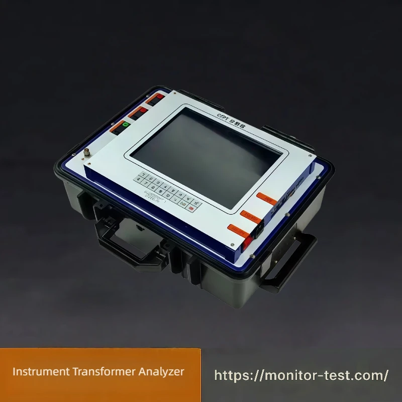
Instrument transformers are the measuring interface of a substation: every meter reading, every protection decision and every energy settlement number passes through a current transformer (CT) or a voltage transformer (VT). They are also the part of the system that is easiest to take for granted — a CT with the right nameplate ratio can still be connected with the wrong polarity, carry the wrong burden, or be saturated under fault current, and none of that is visible from the outside.
That is the reason instrument transformer testing equipment exists, and it is why the test list is longer than most people expect. A ratio check confirms one number; the rest of the tests confirm that the transformer will still behave correctly when it matters.
What instrument transformer testing actually covers
IEEE C57.13.1-2017, the guide for field testing of relaying current transformers, sets out the test set that a field crew is expected to be able to perform. In practice, a CT or VT test set is bought to carry out some or all of the following:
- Ratio test — the actual transformation ratio, and the deviation from the marked or nameplate ratio.
- Ratio error and phase error — the two components of composite error, which is what accuracy class is actually a statement about.
- Polarity test — confirming that primary and secondary are referenced the same way. A CT with correct ratio and reversed polarity feeds protection with a signal inverted by 180 degrees.
- Winding and lead resistance — the internal resistance of the secondary circuit, which sets how much of the available driving voltage is lost before the relay or meter sees it.
- Excitation test — the excitation characteristic, including the knee point, which is what tells you how the CT behaves when the current is far above rated.
- Admittance test — the secondary circuit admittance, most relevant where long secondary runs are involved.
- Burden test and burden measurement — the actual load hanging on the secondary, including cables, relays and meters, measured rather than assumed.
- Insulation resistance — the routine check that a winding is sound before anything else is trusted.
Ratio is not the same as ratio error
The confusion is worth separating, because it decides which instrument gets ordered. A transformer turns ratio tester answers “what is the ratio of this winding pair” — the question that comes up during commissioning, on a suspect unit, or after a tap change. Ratio error and phase error are the metrology question: how far the actual ratio and phase displacement deviate from the ideal, expressed in the accuracy class the transformer is certified to.
A power transformer turns ratio test is a power-transformer test. Instrument transformer testing is a metrology test on a device that has to stay accurate for years while sitting in a switchyard, and it demands specific hardware: calibrators and burden testers rather than a general ratio meter. Our instrument transformer testers cover that second job, from calibrators to burden testers.
Polarity and phase error: the failure that gets found late
Polarity errors are expensive because they are invisible in normal operation and catastrophic in abnormal operation. A reversed CT secondary produces a current signal that looks plausible in steady state and inverts the direction of every current-based decision: directional overcurrent, distance protection and differential protection are all affected at once. That is why the polarity test sits next to the ratio test in the standard rather than being treated as a one-off at installation.
Phase error is the related quantity on the metering side. A CT with excellent ratio accuracy but a phase displacement outside its class will produce a steady, directionless billing error — small per reading, uncorrectable in aggregate after the fact, which is what makes re-verification cycles matter.
Burden: the half of the error that instruments usually miss
Metering error is not one number. It is the sum of several contributions — the energy meter itself, the combined error of the current transformer, the combined error of the voltage transformer, and the error introduced by voltage drop on the VT secondary leads. Where the secondary runs are long, that last term is frequently the largest of the four, and it is the one nobody checks because it belongs to the wiring rather than to any instrument.
Burden testing is how that term is brought under control. The secondary load — relays, meters, transducers and the cable between them — is measured as an actual impedance instead of being taken from a datasheet, and compared against the rated burden the transformer was selected for. Our HF-IT-207 CT burden tester and HF-IT-206 voltage transformer burden tester are built for exactly this measurement, and the HF-IT-208 burden box provides the standardised loads needed to load the circuit up deliberately during verification.
Site testing or laboratory calibration
Both, and for different reasons.
- On site — a portable CT/VT test set is carried to the substation for commissioning, acceptance and periodic verification. The advantage is not convenience but coverage: the reading includes the actual secondary wiring, the actual burden and the actual installation conditions, which is where most real failures live.
- In the laboratory — a calibrator working against a reference standard establishes the error of the transformer itself, free of site effects. This is the traceable measurement, and it is what a dispute or an accreditation requirement will ask for.
A practical programme uses both: laboratory calibration to establish and document the device, field testing to prove that the installed circuit still delivers that accuracy.
Which instrument performs which test
Most CT/VT test sets are bought by test type rather than by model number, so the fastest route is to start from the measurement:
- Excitation, ratio, ratio error, phase error, polarity, winding resistance and hysteresis on one unit — the HF-IT-210 instrument transformer analyzer, a multi-functional CT/PT analyzer covering the full laboratory and field test set.
- On-site verification of CTs and VTs with automatic range adjustment and PC data output — the HF-IT-201 instrument transformer calibrator, the core calibrating instrument of a CT/PT test bench.
- Automatic ratio and volt-ampere characteristic curves, variable frequency, no manual voltage regulation or wiring changes — the HF-IT-202 variable frequency instrument transformer tester.
- Portable on-site CT and VT verification — the HF-IT-203 on-site current transformer tester.
- Comprehensive voltage transformer calibration — ratio error, phase angle deviation, winding resistance, polarity and excitation characteristics in one field device: the HF-IT-204 voltage transformer tester.
- Online ratio and polarity measurement without opening the primary circuit — the HF-IT-205 wireless CT ratio tester, which measures current, transformation ratio, phase identification, polarity and leakage current across high and low voltage sides.
- Burden measurement on CT and VT circuits — the HF-IT-207, the HF-IT-206 and, for the standardised dummy loads used during verification, the HF-IT-208 CT burden box.
- Supplying the variable voltage needed for VT tests — the HF-IT-209 voltage transformer test power supply.
The standards behind the test list
Two bodies of standards matter, and it is worth knowing which generation you are working to.
- IEC 61869 is the current instrument transformer series. It supersedes the older IEC 60044 series — IEC 61869-2 replaces IEC 60044-1 for current transformers, and IEC 61869-3 replaces IEC 60044-2 for inductive voltage transformers. Older test equipment is still routinely specified against IEC 60044-1/-2/-6, so a specification should state the edition it is written to rather than assuming the two are interchangeable.
- IEEE/ANSI C57.13-2016, Standard Requirements for Instrument Transformers, covers the electrical and mechanical requirements plus the test code for ratio and phase angle, demagnetisation, excitation and impedance, polarity and resistance measurement. IEEE C57.13.1-2017, the guide for field testing of relaying current transformers, is the reference to follow when deciding what to test on site and how.
- National verification regulations — in China, JJG 313 and JJG 314 are the verification regulations for current and voltage transformers, and the GB 1208 / GB 1207 / GB 16847 family covers instrument transformer requirements. Our calibration and burden equipment is specified against these alongside the IEC and IEEE references.
Frequently asked questions
What is instrument transformer testing equipment? It is the test equipment used to verify current transformers and voltage transformers rather than power transformers: calibrators that measure ratio error and phase error, ratio testers, polarity and excitation test sets, and burden testers and burden boxes that measure and apply the secondary load.
Is a transformer turns ratio tester the same as an instrument transformer tester? No. A turns ratio tester measures the ratio of power transformer windings during commissioning or fault investigation. Instrument transformer testing is a metrology task on a device that must hold its accuracy class in service, and it needs a calibrator, ratio error and phase error measurement, and burden testing in addition to a ratio check.
Why test CT polarity if the ratio is correct? Because a reversed secondary inverts every current-derived decision in the protection scheme — directional overcurrent, distance and differential protection all misoperate — while normal load current looks entirely plausible. The ratio test cannot detect it.
What does a burden test measure? The actual impedance of the secondary circuit as installed — relays, meters, transducers and cabling — compared with the burden the transformer is rated for. On circuits with long secondary runs, the voltage drop in the leads is often the largest single contribution to metering error.
Can CT ratio be measured without disconnecting the primary? Yes, with a wireless CT ratio tester that clamps the high and low voltage sides and measures current, transformation ratio, phase identification and polarity online. That matters where the primary cannot be taken out of service for a conventional test.
If you are not sure which test set the job needs, tell us the transformer type, the tests your procedure requires and whether the unit is in service or on the bench — the instrument transformer tester range covers calibrators, ratio testers, burden testers and the power supplies and burden boxes that complete a CT/PT test set.