Leave your message

-
Leon Zhang sales consultant
-
Email: zxl635973785@gmail.com
-
Phone/WhatsApp/Wechat: +86 13655813266

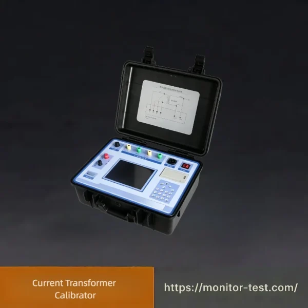
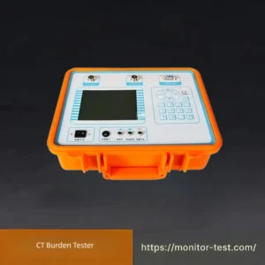
HF-IT-203 Current Transformer Calibrator
This portable Current Transformer Calibrator is designed for on-site verification of current and voltage transformers. It adopts advanced variable frequency anti-interference technology, needs no extra auxiliary devices, delivers high-precision error testing and supports data storage and report output for power system calibration work.
Send your requirements, we will quote for you within 12 hours
The HF-IT-203 On-Site Current Transformer Tester is developed adopting advanced testing technologies, large-scale electronic circuit design and compliance with relevant national standards.
It effectively solves the problems of heavy workload and cumbersome operations during on-site verification of current transformers (CT) and voltage transformers (VT), featuring reliable performance and powerful comprehensive functions.
It effectively solves the problems of heavy workload and cumbersome operations during on-site verification of current transformers (CT) and voltage transformers (VT), featuring reliable performance and powerful comprehensive functions.
Technical Specifications Table
| Parameter Item | Detailed Specifications |
|---|---|
| Transformation Ratio Test Range | 5A/5A ~ 25000A/5A;5A/1A ~ 6300A/1A |
| CT Operating Test Range | 1% ~ 200% of rated current |
| Secondary Burden | 0 ~ 300VA, Power factor cosφ = 0.1 ~ 1.0 |
| Supported CT Accuracy Classes | 1.0、0.5、0.5S、0.2、0.2S |
| Resistance & Admittance Measuring Error | ≤5.0% |
| Resistance Measurement Range (R) | 0.00Ω ~ 20.0Ω |
| Admittance Measurement Range (Y) | 0.000mS ~ 100.0mS |
| Built-in Calibrator In-phase Component Error | ΔX=±(X×2%+Y×2% ± 2 digits) |
| Built-in Calibrator Quadrature Component Error | ΔY=±(X×2%+Y×2% ± 5 digits) |
| Error Formula Annotation | X,Y: Instrument display values
Digits: Instrument quantization error |
| Percentage Meter Accuracy | Class 1 |
| Ratio Error Measuring Range (f) | 0.0000% ~ 200.0% |
| Phase Error Measuring Range (δ) | 0.000′ ~ 999.9′ |
| Total Power Consumption | 20VA |
| Instrument Overall Accuracy Grade | 0.05S |
| Overall Dimensions | 460mm(L) × 375mm(W) × 183mm(H) |
| Total Weight | Main body: 11kg;Accessories: 3.5kg |
Product Features
- Integrates two testing methods: recursive algorithm for CT error measurement and potential difference method for VT error measurement, greatly facilitating on-site verification of power metering devices.
- No auxiliary equipment including standard CT, current booster, burden box, voltage regulator cabinet and high-current cables is required for on-site CT calibration. Simple wiring and operation drastically reduce labor intensity and improve testing efficiency for field transformer verification.
- Equipped with an internal standard voltage transformer with the same transformation ratio as the tested CT (accuracy up to 0.05S class). It precisely measures CT transformation ratio and no-load errors, then calculates overall transformer errors combined with impedance and admittance test results.
- Powered by near-power-frequency variable-frequency source to avoid interference from on-site power-frequency electromagnetic radiation and series coupling disturbance.
- Ultra-wide measurement range: covers ratios from 5A/5A up to 25000A/5A, and 5A/1A up to 6300A/1A.
- Supports CT transformation ratio detection and secondary winding DC resistance measurement.
- Fitted with 800×600 high-resolution large LCD touch screen; humanized interface and touch control make operations simpler and faster.
- Optimized advanced software algorithm ensures higher precision of measured data.
- Intelligent wiring diagnosis function: automatically alerts users to wrong wiring, incorrect transformation ratio and reversed polarity.
- Automatically rounds off test data and judges out-of-tolerance conditions. Out-of-limit values are highlighted in orange with prompt marks at the window corner for intuitive checking of transformer performance characteristics.
- Directly generates official on-site verification conclusions: Passed / Out of Tolerance.
- Large-capacity internal memory stores up to 1000 groups of field test records.
- Equipped with RS232 and USB communication ports for PC connection, enabling data export and verification certificate printing.
- Robust engineering plastic molded casing features shockproof and pressure-resistant properties, ensuring operator safety and reliable equipment protection under harsh field environments.
Packing List: Current Transformer Calibrator
|
No.
|
Item Name
|
Qty
|
Unit
|
Remarks
|
|---|---|---|---|---|
|
1
|
Current Transformer Calibrator Main Unit
|
1
|
Set
|
0.05S high precision grade
|
|
2
|
Special Test Connecting Cables
|
1
|
Set
|
For CT on-site calibration
|
|
3
|
220V AC Power Cord
|
1
|
Pc
|
Power supply connection
|
|
4
|
User Manual (English & Chinese)
|
1
|
Copy
|
Complete operation guide
|
|
5
|
Factory Calibration Certificate
|
1
|
Copy
|
Official metering qualification
|
|
6
|
USB & RS232 Communication Cable
|
1
|
Set
|
For data export and report printing
|
|
7
|
Shockproof Protective Carrying Case
|
1
|
Pc
|
Convenient for field transportation
|
|
8
|
Spare Fuses
|
2
|
Pcs
|
Standby replacement parts
|
FAQ: Current Transformer Calibrator (CT Calibrator / CT Analyzer)
Q1: What is a Current Transformer Calibrator?
A1: It is a portable integrated test instrument designed to calibrate and characterize all types of current transformers (CTs). It measures CT ratio error, phase error, excitation curve, knee-point voltage, secondary winding resistance, secondary burden, polarity, and calculates ALF, FS, TS safety factors, complying with international CT calibration standards for metering & protection CTs in substations, power plants and industrial power systems.
Q2: What types of CTs can this calibrator test?
A2: It supports wound CT, bushing CT, GIS CT, split-core CT, Rogowski coil CT, indoor/outdoor high & medium voltage CTs; compatible with both metering class CT (0.2S/0.5S) and protection class CT (5P/10P/TPY) widely used in power grids.
Q3: What core tests can the CT calibrator perform automatically?
A3: 1) Ratio & phase angle error calibration under rated burden; 2) Excitation characteristic curve test & knee point calculation; 3) Secondary winding DC resistance measurement; 4) Actual secondary burden test; 5) Polarity check; 6) CT insulation withstand test; 7) Auto generation of standardized test reports.
Q4: What measurement accuracy does your CT calibrator offer?
A4: Basic measurement accuracy: ±0.05% ~ ±0.1% for ratio error, ±1′ ~ ±2′ for phase angle error. It meets Class 0.1 reference standard requirements, fully qualified for official metrology verification of revenue-grade billing CTs.
Q5: Which international standards does the device comply with?
A5: Designed per IEC 61869 (instrument transformers), IEEE C57.13, and national grid calibration codes; test data and reports are accepted by power utilities and third-party metrology labs worldwide.
Q6: How often should in-service CTs be calibrated with this device?
- New CTs: Full calibration before grid commissioning (mandatory)
- Metering CTs (energy billing): Every 1–3 years
- Protection CTs: Verified annually together with protection relays
- Extra immediate testing required after grid short-circuit faults, abnormal meter readings or equipment overhaul
Q7: Why must the calibrator casing be reliably grounded during field testing?
A7: Substation sites contain strong induced high voltage. Good grounding eliminates stray interference, ensures measurement precision, and prevents electric shock hazards for operators caused by residual induced voltage on the instrument shell.
Q8: Can we test CTs while the power system is energized?
A8: Absolutely forbidden. CT secondary terminals shall never be open-circuited under live conditions, which will generate dangerous high voltage and damage both CT and calibrator. All CT primary & secondary circuits must be fully isolated and de-energized before any test connection.
Q9: How does wire resistance affect CT error test results?
A9: Connecting lead resistance directly adds to CT secondary burden. For small rated burden CTs (5VA/10VA), wire resistance will cause obvious error deviation. We recommend short, thick test cables and reserve about 0.06Ω wire resistance margin during burden setup for accurate data.
Q10: Why is CT polarity test so critical for power protection systems?
A10: Differential protection, directional relays rely on correct current phase direction. Reversed CT polarity will make protective relays mistake normal load current for internal faults, triggering unnecessary breaker tripping and widespread power outages. Polarity check is a compulsory pre-test step for all protection CTs.
Reviews
There are no reviews yet.