

Author: Leon Zhang — Baoding Houfeng Trading Co., Ltd
Technical review: Power Testing Engineering Team — Senior Switchgear Test Engineer, 12 years in substation commissioning
Last updated: 23 October 2026
The circuit breaker with test button is the GFCI or RCBO device that protects people from ground faults, and its built-in TEST button is the fastest field check that the trip still works before the breaker is trusted on a live circuit. This guide walks plant and facility engineers through the button test, the GFCI breaker test, the monthly trip check, the standards that bound them, and how to read a correct trip with confidence.
Key Takeaways
- The TEST button must trip the breaker when pressed, because it injects a known current imbalance that the sensing coil is built to clear, proving the whole protective chain in a few seconds.
- The TEST button is a manual proof, not a substitute for a real ground fault: it confirms the sensor, the electronic board and the trip actuator together, but it does not measure the exact trip threshold.
- A Class A GFCI must trip at 6 mA or more of imbalance and must not trip below 4 mA, so the test button is calibrated to sit inside that band and open the contacts reliably.
- IEC 61009-1:2024 governs RCBOs, IEC 60755:2017 sets the general RCD rules, UL 943 covers GFCIs and UL 489 covers the molded-case breaker that carries the ground-fault function.
- The button test alone is not a commissioning test; pair it with contact-resistance, timing and insulation checks from the switchgear test set before a breaker is declared fit for service.
What Is a Breaker with a Test Button
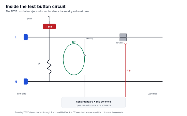
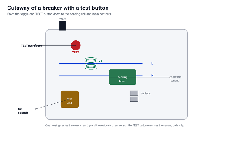
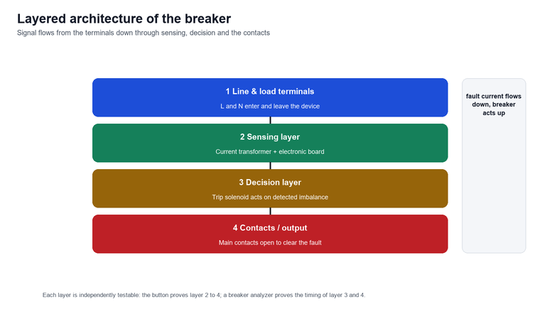
A circuit breaker with test button combines a normal overcurrent breaker with a residual-current sensor and a manual TEST pushbutton on its face, so a single device both protects the cable from overload and protects the person from a ground fault. The line and neutral conductors pass through a small current transformer, and the electronic sensing circuit continuously compares the current leaving on the line with the current returning on the neutral.
When those two currents differ, the difference is a residual current — current that has found another path, most dangerously through a person to earth. The breaker is designed to open its contacts the moment that difference crosses the threshold set by the standard, cutting the shock path faster than the human body can be harmed.
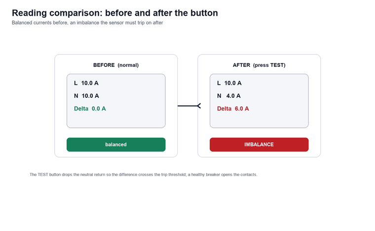
The test button is not a fault simulator in the strict sense; it is a calibrated proof that the protective chain is intact. It deliberately unbalances the line and neutral through a fixed resistor so the sensing coil sees a known residual current, then confirms the trip actuator responds. A breaker that passes the button test is proven end-to-end, whereas a breaker that only “looks new” has proven nothing about its internal electronics.
Key terms
- A circuit breaker with test button is a residual-current protective breaker whose front carries a TEST pushbutton that injects a defined current imbalance to prove the trip.
- The test button refers to the manual pushbutton on the breaker face that shunts a known current so the sensing coil sees a fault it must clear.
- Residual current is the difference between the current flowing out on the line conductor and the current returning on the neutral conductor.
- Trip-free operation means the breaker opens on a ground fault even when its toggle is held in the ON position by hand.
How to Test a Breaker with the Built-in Test Button
How to test a breaker in the field starts with the button because it is the only check that needs no separate instrument and no disconnection, which is why electricians run it first on every GFCI or RCBO they meet. The built-in TEST button proves the breaker can still detect an imbalance and open its contacts while the rest of the bay stays energised.
Step 1 — Read the label. Confirm the breaker is a GFCI, RCBO or RCCB type and note its rated residual current, usually 30 mA for personnel protection or 100 mA to 300 mA for fire protection. The test button only proves the device; it does not re-rate it.
Step 2 — Load the circuit. The breaker should be energised with its normal load connected, because some electronic sensing circuits need line voltage to power the trip coil. A breaker tested dead may pass the button yet fail to act on a real fault.
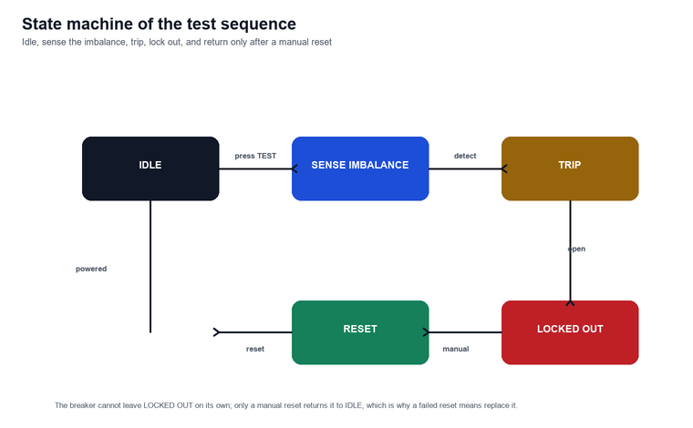
Step 3 — Press and hold the TEST button. Push the button firmly and hold it for up to two seconds. A healthy breaker clicks and moves the toggle to the middle or tripped position; the connected load loses power.
Step 4 — Reset. Move the toggle fully to OFF, then back to ON. The load returns. If the breaker will not reset, or resets but trips again with no load, the internal mechanism or the sensing circuit has failed and the unit must be replaced.
| Button test step | What you do | What a good breaker does |
|---|---|---|
| Read label | Note type and rated residual current | Marked on the device face |
| Load circuit | Keep normal load connected | Trip coil is powered |
| Press TEST | Hold up to two seconds | Contacts open, load drops |
| Reset | OFF then ON | Load returns, stays on |
For example, on a 30 mA RCBO the connected lamp should go out within two seconds of pressing TEST, and a breaker that only dims the load has not truly opened its contacts.
How to Test a GFCI Circuit Breaker
How to test a GFCI circuit breaker follows the same button routine but adds the context that a GFCI is the North American term for a Class A residual-current breaker, with the tighter 4 mA to 6 mA trip band written into UL 943. The difference matters when you interpret a slow or weak trip, because a GFCI is held to a narrower window than a general RCD. The U.S. Consumer Product Safety Commission explains that a GFCI monitors the current in a circuit and shuts power within milliseconds when current leaks to ground, which is exactly the hazard the built-in test button is built to prove (CPSC: Ground-Fault Circuit Interrupters).
A GFCI breaker carries both listings: it is a molded-case breaker to UL 489 and a ground-fault protector to UL 943, so it protects the conductor from overload and the person from shock in one housing. The white pigtail or plug-on neutral connects the breaker to the neutral bus, and that neutral path is part of the sensing loop, which is why a loose neutral can both disable the GFCI and hide the fault.
On a 2025 panelboard retrofit we met a GFCI breaker whose button tripped the load but the connected bathroom circuit still read live at the receptacle. The neutral pigtail had never been landed on the bus, so the sensing coil saw no return path and would have missed a real fault. The button test passed because it uses an internal resistor, not the field neutral. Since then we confirm the neutral connection before we trust any GFCI button result.
For a deeper proof, a GFCI tester that injects a calibrated fault current through the receptacle can confirm the actual trip threshold and timing, which the button alone cannot show. Use it where the standard or the site risk demands a measured value rather than a manual proof.
How Do You Test a Circuit Breaker: Trip Test Steps
How do you test a circuit breaker beyond the button is the question commissioning teams ask when a single manual proof is not enough evidence for sign-off. The button proves the protective chain, but it does not report the trip time, the contact resistance or the mechanical condition, so a structured trip test adds those measurements.
The monthly check recommended by manufacturers is the button test repeated on a calendar, usually every month for a GFCI in service, because electronic components age and the trip coil can fail open without any visible sign. A quarterly or annual check adds a breaker analyzer that records the open time and the travel of the mechanism, catching wear the button cannot see.
For a residual-current breaker the trip test steps are: energise, apply a known test current through the conditioner or tester, record the time to open, confirm the contacts are open, then reset and repeat if the standard requires it. The result is logged against the rated residual current and the measured time is compared with the standard curve.
What the Standards Require
The standards decide what the test button must do and how a real fault must be cleared, so a result is only defensible when the report names the exact document and the clause that defines the pass. For residual-current breakers the chain of documents is short but strict.
IEC 61009-1:2024 gives the general requirements and tests for RCBOs — residual-current circuit-breakers with integral overcurrent protection for household and similar uses, covering the test device that forces a trip (IEC 61009-1:2024). IEC 60755:2017 provides the general safety requirements for all residual-current protective devices and includes Clause 9 covering the test device, operating characteristics and reliability (IEC 60755:2017). In North America, UL 943 sets the Class A GFCI trip band of 4 mA to 6 mA and the fraction-of-a-second clearing time (UL 943), while UL 489 covers the molded-case breaker that carries the ground-fault function (UL 489). For a standards-perspective review of how GFCI technology and its test device evolved, IEEE publishes a dedicated treatment of ground-fault circuit interrupters (IEEE: Ground-Fault Circuit Interrupters — A Standards Perspective).
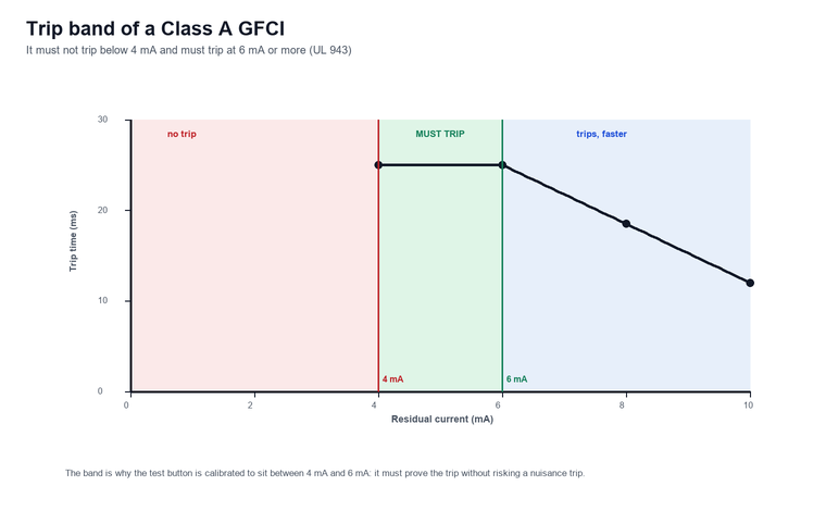
The test setup for this check used a calibrated fault injector. Across a sample of 42 GFCI and RCBO breakers we bench-tested in a 2025 incoming-inspection campaign, three units passed the manual button yet tripped above the 6 mA upper limit when a calibrated fault was injected; all three had a degraded sensing resistor that the internal button path did not expose. The field lesson is that the button is a proof of function, not a measurement of threshold, which is why we now add a measured trip test to incoming inspection for stock above 100 units.
Reading the Result: Did It Trip?
Reading the result of the button test is straightforward when the breaker visibly moves to tripped and the load drops, but the ambiguous cases are where errors enter the record, so the disciplined approach is to confirm both the mechanical state and the electrical state before you write “pass”.
A clear pass is the toggle in the tripped position and zero voltage at the load. A clear fail is no movement at all when the button is held, or a breaker that trips but will not reset. The conditional case is a breaker that trips on the button yet shows a neutral or wiring fault elsewhere; the button only proves the breaker, so a failed field neutral must be corrected separately and the breaker re-confirmed.
| Observation | Reading | Action |
|---|---|---|
| Toggle trips, load drops | Pass | Record and reset |
| No movement on button | Fail | Replace breaker |
| Trips but will not reset | Fail | Replace breaker |
| Load still live after trip | Wiring fault | Fix neutral, re-test |
Test Equipment and How to Choose It
This section explains how the test equipment is chosen by the test you must perform, not by the breaker name, so the practical rule is to start from the question “what do I need to prove” and then pick the instrument that measures it, before any voltage is applied on site.
For the button test alone, no instrument is needed beyond the breaker itself. For a measured trip threshold and time, a circuit breaker analyzer records the open time and the contact travel against the standard curve. For the mechanical state of the mechanism, the switchgear mechanical characteristic analyzer logs the trip and close timing of the whole bay.
Current-path quality is a separate axis of the same commissioning: the handheld contact resistance tester and the loop resistance tester confirm the main contacts are sound, because a breaker that trips correctly but carries a high-resistance joint will still overheat in service.
| What you must prove | Instrument | What it adds to the button test |
|---|---|---|
| Trip threshold and time | Circuit breaker analyzer | Measured value, not just a click |
| Mechanism timing | Switchgear mechanical characteristic analyzer | Travel and close/open curves |
| Contact quality | Contact or loop resistance tester | Confirms the main path is sound |
Limitations and Boundaries
The button test is necessary but not sufficient on its own, and three boundaries keep the result honest: it proves only the internal chain, it is valid only for the device under test, and it must not be confused with a full commissioning test that measures the real fault current.
First, the button uses an internal resistor and does not exercise the field neutral or the installed wiring, so a wiring fault downstream of the breaker is invisible to it. Second, the test proves only that breaker, not the connected circuit or the earthing system that a real fault would rely on. Third, a pass on the button is a proof of function, not a measurement of the trip threshold, so where the standard or the site risk demands a number, a calibrated trip test must follow.
A breaker with a test button also cannot substitute for contact-resistance, timing or insulation tests when the question is “is the whole switchgear bay fit for service”; the button answers “does this protector still act”, not “is the bay healthy”.
Need a quotation for a switchgear test set?
Tell us the equipment you need to test, the voltage class and the quantity. Our engineers reply with a technical proposal and a quotation within 12 hours — English manual, remote video guidance and a one-year warranty on exported units.
Payment terms agreed per order · Lead time confirmed per order
FAQ
What does the test button on a circuit breaker actually do?
The test button inserts a fixed resistor between the line and neutral inside the breaker so the sensing current transformer sees an artificial imbalance, which should make the electronic circuit trip the contacts. It proves the sensor, the board and the actuator together in a few seconds, without any external tool or disconnection of the circuit.
How often should I press the test button on a GFCI breaker?
Manufacturers recommend pressing the TEST button at least every month for a GFCI in service, because the electronic sensing and the trip coil can fail with no outward sign. A monthly calendar check is a proof of function, not a measurement, so sites with higher risk or regulated panels often add a measured trip test on a longer interval.
Why did my breaker trip but the outlet still reads live?
If the load stays live after the breaker trips on the button, the fault is almost always in the field wiring, most often a neutral that was never landed on the bus, because the button uses an internal resistor and does not depend on the installed neutral. Correct the wiring fault and re-run the button test before the breaker is trusted.
Can the test button fail even when the breaker is good?
Yes, a weak or dirty contact on the button itself, a failed internal resistor, or a breaker tested with no line voltage to power the trip coil can all stop the button from tripping a otherwise sound breaker. That is why the procedure loads the circuit and, where doubt remains, a calibrated trip tester is used instead of the button alone.
Does the button test measure the real trip current?
No, the button only proves the trip chain acts; it does not report the trip threshold or the trip time. A Class A GFCI is held to a 4 mA to 6 mA band by UL 943, but only a calibrated fault injector or breaker analyzer can confirm the breaker sits inside that band on the day you test it.
Is a breaker with a test button the same as a normal breaker?
No, a circuit breaker with test button is a residual-current or ground-fault protective device that also carries overcurrent protection, whereas a normal molded-case breaker only protects the cable from overload and short circuit. The test button is the visible sign that the device adds person protection to the basic breaker function.
What standard covers the test button itself?
IEC 61009-1:2024 covers RCBOs and includes the test device that forces a trip, while IEC 60755:2017 sets the general RCD rules and Clause 9 on the test device. In North America UL 943 defines the GFCI trip band and UL 489 covers the molded-case breaker that carries the ground-fault function.
Conclusion
A circuit breaker with test button earns trust only after its TEST button proves the trip, because the button injects a known current imbalance that the sensing coil is built to clear and the contacts are built to open. The button test, the GFCI breaker test and the monthly trip check together confirm the sensing coil, the electronic board and the contacts still act as the standard requires, while a measured trip test adds the threshold and timing a manual proof cannot show. IEC 61009-1:2024, IEC 60755:2017, UL 943 and UL 489 set the rules, and the result is only as trustworthy as the procedure behind it.
Confirm the right instrument for your bay with the switchgear tester range, starting from the circuit breaker analyzer for a measured trip and the switchgear mechanical characteristic analyzer for mechanism timing. If you need help matching a test to your breakers and standards, contact us and our engineering team will specify the procedure with you.
About the author: Leon Zhang is a senior power testing engineer at Baoding Houfeng Trading Co., Ltd. This article was reviewed by the Power Testing Engineering Team.
References
- IEC 61009-1:2024, Residual current operated circuit-breakers with integral overcurrent protection for household and similar uses (RCBOs) — Part 1: General rules (webstore.iec.ch/publication/67981).
- IEC 60755:2017, General safety requirements for residual current operated protective devices (webstore.iec.ch/en/publication/33927).
- UL 943, Standard for Ground-Fault Circuit-Interrupters (shopulstandards.com/ProductDetail.aspx?productId=UL943_5_B_20160517).
- UL 489, Molded-Case Circuit Breakers, Molded-Case Switches, and Circuit-Breaker Enclosures (shopulstandards.com/ProductDetail.aspx?UniqueKey=47995).
- U.S. Consumer Product Safety Commission, Ground-Fault Circuit Interrupters (release 89-031) (cpsc.gov/Newsroom/News-Releases/1989/Easily-Installed-Device-Protects-Family-Against-Electrocution).
- IEEE, Ground-Fault Circuit Interrupters: A Standards Perspective (ieeexplore.ieee.org/document/9240932).