Leave your message

-
Leon Zhang sales consultant
-
Email: zxl635973785@gmail.com
-
Phone/WhatsApp/Wechat: +86 13655813266

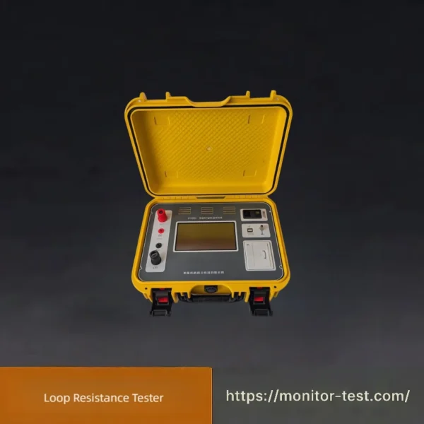
HF-WC-601 Loop Resistance Tester
This portable Loop Resistance Tester applies the 4-wire Kelvin principle. With stable DC high current output, it accurately measures tiny contact resistance of circuit breakers and switches, featuring reliable data, easy operation and complete safety protection for power system maintenance.
Send your requirements, we will quote for you within 12 hours
HF-WC-601 Series Intelligent Loop Resistance Tester is developed with advanced high-power switching power supply technology and sophisticated electronic circuits. It is a dedicated testing instrument used to measure contact resistance for high & low voltage switches, power cables, wires and welding joints.
It supplies standard DC current compliant with GB736 national standard, enabling accurate resistance measurement of test samples under standard conditions. This loop resistance tester boasts compact body, lightweight design, strong anti-interference performance, high measuring precision, simple operation and comprehensive protective functions.
It supplies standard DC current compliant with GB736 national standard, enabling accurate resistance measurement of test samples under standard conditions. This loop resistance tester boasts compact body, lightweight design, strong anti-interference performance, high measuring precision, simple operation and comprehensive protective functions.
Core Keywords Embedded: Intelligent Loop Resistance Tester, Contact Resistance Tester, Loop Resistance Test Equipment
Main Features & Functions
-
7-inch HD Color Touch Screen & Built-in Thermal Printer
800×480 high-definition color touch screen delivers smooth human-machine interaction; equipped with a high-speed thermal printer for instant test report printing.
-
Multi-Gear Large Continuous Current Output
Equipped with updated power supply hardware to output stable large current continuously for long-time tests. You can select 1 to 3 different current ranges for measurement, and the device will automatically calculate the average resistance value.
-
Multi-Parameter Real-time Display & Standard Temperature Conversion
Simultaneously shows resistance, voltage, current and resistivity values; automatically converts measured resistance to the resistance value under standard ambient temperature via built-in temperature compensation algorithm. -
Automatic Over-Limit Resistance Alarm Function
Set the upper limit threshold of resistance in advance. The tester will automatically distinguish qualified, over-limit and invalid test results and trigger corresponding alarm prompts.
-
Long-Duration Continuous Measurement Support
Adjustable test time range: 0 ~ 9999 seconds, supporting uninterrupted long-hour operation. Built-in air cooling heat dissipation system and automatic overheat protection for internal switching power supply.
-
Ultra-High Measuring Precision
Adopts precision operational amplifiers and 4-fold integrating A/D converter, greatly improving the accuracy of micro-ohm resistance testing.
-
32-bit ARM High-Speed Main Control Chip
Latest 32-bit ARM microprocessor is adopted; the system automatically switches signal amplification multiples according to measured signal strength to guarantee stable and precise test results. -
Built-in Real-Time Calendar Clock
Integrated calendar & timing module, providing accurate time stamps for all stored test data and printed reports. -
Adjustable DC Constant Current Source (Multi-Purpose Design)
Output DC current continuously adjustable from 0 to maximum rated current, supporting step-up progressive current tests. One single device can replace multiple independent DC constant current sources to cut procurement costs.
-
Large-Capacity Offline Test Data Storage
Mass internal memory stores thousands of groups of test records. It supports data browsing, query and power-off data retention to avoid accidental data loss. -
USB Flash Drive Data Export to Excel
Standard USB interface allows users to export all saved test data to a USB drive and generate editable Excel files for later sorting and analysis.
-
Modbus-RTU Industrial Communication Protocol
Comes with standard RS232 communication port; RS485 port is optional for upgrade. It fully complies with Modbus-RTU protocol for industrial system docking.
-
PC Remote Control & Word/Excel Report Generation
Connect the device to a computer via RS232 serial port to realize remote operation, data uploading, and automatic generation of Word & Excel test reports on PC terminals. -
Bluetooth Wireless Control & Data Upload
Bluetooth module is standard configured, matched with dedicated Android APP. You can complete device control, data transmission and Word report generation wirelessly via mobile phones. -
External Line Trigger Control (Optional) For Assembly Line Work
Suitable for batch testing on production lines. An external switch can start, pause or terminate tests. A warning indicator will light up once the measured resistance exceeds the preset limit. -
Wireless Remote Controller (Optional)
Supports one-click start and stop of tests; the customized remote controller can display real-time test status to simplify on-site operation.
-
Dual Modes Temperature Compensation Calculation
You can preset standard temperature values to convert resistance readings; or connect an optional external temperature sensor to collect actual ambient temperature for more accurate conversion.
-
Customizable Screen Display Interface
Adjust screen background styles (textured blue background / textured black background optional), display brightness, standby brightness and standby time according to personal habits.
-
Built-in On-Site Wiring Tutorials
Detailed wiring diagrams and operation guides are stored inside the device, helping field technicians finish wiring and commissioning quickly.
-
Chinese Input for Test Information Marking
Support Chinese text entry to fill in substation numbers, equipment codes, staff information and remarks. Custom labels will be saved together with test data for convenient filing and printed report identification.
-
Quick Plug Connection for High-Current Cables
Adopts new-style quick connectors for heavy-current wires; just insert and twist tightly to complete wiring efficiently, saving plenty of preparation time.
-
Multi-Phase Measurement Customization Options
Standard configuration: Single-phase measurement. Optional upgrades: Two-phase synchronous test (special for conductor resistance measurement) or Three-phase synchronous test to meet diversified power detection demands.
Technical Specifications
| Item | Model 100A | Model 200A | Model 300A | Model 400A | Model 500A | Model 600A | Custom 10~5000A |
|---|---|---|---|---|---|---|---|
| Current Measuring Ranges
(Customizable) |
50A 100A Custom |
50A 100A 150A 200A Custom |
50A 100A 150A 200A 300A Custom |
50A 100A 150A 200A 300A 400A Custom |
50A 100A 150A 200A 300A 400A 500A Custom |
50A 100A 150A 200A 300A 400A 500A 600A Custom |
Custom Single-phase Custom Two-phase Custom Three-phase |
| Measuring Range | colspan=”7″ | 0 ~ 19999 mΩ (Expandable) | |||||
| Accuracy | colspan=”7″ | 0.5% reading ± 100 digits | |||||
| Resolution | colspan=”7″ | 0.01 mΩ | |||||
| Power Supply | colspan=”7″ | AC 220V ±10%, 50Hz ±2% | |||||
| Length (mm) | 450 | 450 | — | — | — | — | Custom |
| Width (mm) | 250 | 250 | — | — | — | — | Custom |
| Height (mm) | 220 | 280 | — | — | — | — | Custom |
| Net Weight (kg) | 9.9 | 12.9 | — | — | — | — | Custom |
| Operating Ambient Temperature | colspan=”7″ | -25℃ ~ 50℃ | |||||
| Relative Humidity | colspan=”7″ | ≤ 90% RH (No condensation) |
Simplified Operation Steps for Loop Resistance Tester
-
Preparations
Ensure the tested electrical equipment is fully de-energized and grounded. Clean terminal oxide and dirt. Check tester and test cables for intact condition.
-
Four-wire Wiring
Connect thick current clamps outside the test points, thin voltage clamps inside them. Attach the ground wire and mains power supply.
-
Parameter Setup
Power on the device to finish self-check. Select DC test current (50A/100A) and confirm settings.
-
Carry Out Measurement
Hit Start to test. Record the displayed loop resistance value after the test ends. Test 2-3 times and average the results.
Reconnect cables if poor connection or overload alerts pop up.
-
Post-test Work
Save or print test data as required. Stop output current, wait for discharge, then power off. Disconnect leads and pack all accessories properly.
FAQ | Loop Resistance Tester
1. What is a loop resistance tester used for?
This instrument is designed to accurately measure the contact loop resistance of high voltage circuit breakers, disconnecting switches and busbar joints. It helps inspect contact tightness, abrasion and oxidation conditions to guarantee safe operation of power switchgear.
2. Why does the tester use the 4-wire Kelvin testing method?
The four-wire connection effectively removes resistance errors brought by test cables and clamps. It ensures high precision when testing tiny micro-ohm level resistance values.
3. My measured readings keep fluctuating, how to fix it?
Unstable data is mainly caused by oxidized/dirty terminals, loose clamps or incorrect wiring. Clean the contact surfaces thoroughly and fasten all test clips tightly before retesting.
4. The screen prompts Poor Connection, what should I check?
Check for damaged test leads, loose plug connections or loosely fixed clamps. Rewire the whole circuit correctly to solve the problem.
5. Do voltage clamps have to be placed inside current clamps?
Yes. Voltage sampling clips must be installed between the two current clamps. This layout is required for accurate resistance measurement.
6. Should I select 50A or 100A DC test current?
100A DC is the standard test current for most high-voltage switch equipment. 50A is suitable for small-capacity low-voltage switches only.
7. Can I conduct continuous high-current tests repeatedly?
No. Long-time high-current output will overheat the internal power components. Leave proper cooling time between multiple tests.
8. What does OL displayed on the screen mean?
OL stands for over range. It occurs when the circuit is open or the measured resistance exceeds the instrument’s maximum measuring range. Please check wiring and equipment contacts.
9. Zero drift appears after power on, how to adjust?
Run the built-in auto zero calibration program during startup. Make sure all clamps are disconnected during the zeroing process.
10. Is it permitted to test energized electrical equipment?
Absolutely prohibited. All equipment must be fully powered off, locked out and grounded prior to testing for personal safety.
11. How to maintain and store the tester when not in use?
Store the device in a dry, dust-free and well-ventilated space. Neatly arrange all test cables to prevent wire fracture.
12. Can this tester measure transformer winding resistance?
It is not recommended. Loop resistance testers are dedicated to switch contact resistance tests, not applicable for inductive transformer windings.
Reviews
There are no reviews yet.