

Author: Leon Zhang — Power monitoring and testing equipment team, Baoding Houfeng Trading Co., Ltd., specifying high voltage test instruments for substations, plants and commissioning contractors
Technical review: this guide passed editorial review and was checked against IEEE Std 4-2013, IEC 60502-2:2014 and IEEE 400.2-2013 before publication
Last updated: 21 October 2026
Hi pot: A practical guide for substation and plant engineers
A hi pot test applies a voltage well above normal service voltage to insulation that is not in service, and watches what current flows. That single sentence covers most of the equipment on the market and most of the arguments about it. The word is shop shorthand for high potential — the potential test, the pressure test, the overvoltage proof — and every version of it answers the same question: will this insulation hold, or will it break down while the equipment is still new enough to fix cheaply? This guide walks through what the test measures, how it differs from an insulation resistance test, where the test voltage number actually comes from, and how to set up and read a test without damaging healthy equipment.
Key takeaways
- The proof test stresses insulation at a fixed overvoltage for a fixed time and judges it by whether breakdown occurs and how much leakage current flows, which is a proof, not a measurement of quality.
- Hi pot vs megger is not a choice between rivals: the megohmmeter measures insulation quality at low stress, and the overvoltage proof answers the survive-or-not question. Most programmes run both, in that order.
- The test voltage is not a personal preference. It comes from the equipment standard, the type test value, and whether the test is an acceptance test or a maintenance test, and maintenance tests are run at a reduced level, typically three-quarters of the acceptance value.
- AC, DC and very low frequency excitation each stress the insulation differently, and picking the wrong one for a long cable or a rotating machine can either miss the defect or damage good insulation.
- A breakdown is only the most obvious failure. Steadily rising leakage current during the hold period is the subtler warning, and it is the one an unattended test setup will miss.
Introduction
The first test set many engineers meet is a grey box with a red lead, a green lead, a knob and a trip light, and the instructions in the plant file say something like: apply 2 kV for one minute, record the reading. The box makes the test look trivial. It is not. The voltage applied during the test is often several times the working voltage, the energy available at the terminals is enough to burn a hole through a winding, and the difference between a test that proves the insulation and a test that destroys it sits in the setup, the ramp and the judgement of the leakage reading.
This guide is written for the engineer who has to run the test, choose the instrument, or write the acceptance criteria for others to follow. It covers the physics briefly, the standards that set the numbers, the practical differences between AC, DC and VLF excitation, a step-by-step setup procedure, and the interpretation questions that cause arguments on site: what leakage current is acceptable, when a rising trend matters, and when to stop the test before something fails.
What the proof test actually measures
Insulation fails in one of two ways, and the proof test is built to catch either of them while the equipment is still out of service and cheap to fix. It can conduct too much current through its volume or across its surfaces, which shows up as leakage; or it can break down completely, which shows up as a collapse of voltage and a jump in current. The proof test watches for both. The applied voltage forces the electric field inside the insulation several times higher than service, and any void, contamination path, moisture bridge or damaged strand that could sustain a partial discharge or a tracking path at overvoltage is given every chance to reveal itself.
A hi pot test is a proof test, not a measurement test. It does not return a quality grade for the insulation. It returns a binary result — withstood or did not withstand — plus a leakage current reading that supports judgement. That is why the test is popular as an acceptance gate on new equipment and after repairs: it answers the pass-or-fail question that commissioning needs, quickly and unambiguously.
The current that flows during the test has several components, and knowing them separates a competent reading from a wrong one:
- Capacitive charging current flows as the test object charges up, is large at first, and falls to nearly nothing on a DC test within seconds to minutes depending on the capacitance.
- Absorption current flows into the insulation itself as the dielectric polarises, decays slowly over minutes.
- Surface leakage current flows across dirty or damp external surfaces, and is the component most affected by humidity, contamination and the state of the insulating surfaces — which is why a clean and dry test object matters as much as a healthy one.
- Volume conduction and partial discharge current are the small, steady components that indicate the actual condition of the insulation bulk.
On a DC test the capacitive component dominates the first moments and then fades, which is why a leakage-versus-time curve is worth recording rather than a single end-of-test number.
Hi pot vs Megger: two tests that look similar
The two tests use the same physics, the same terminals and much of the same vocabulary, and they get confused constantly on site. The distinction is in the stress level and the question asked, and getting it right matters because substituting one for the other either wastes time or damages equipment.
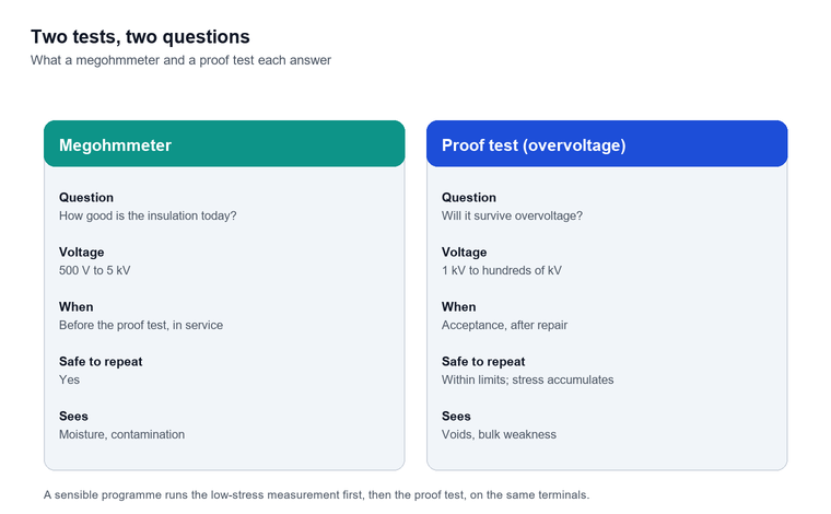
A megohmmeter — the insulation resistance tester, the megger in everyday speech — applies a modest direct voltage, commonly 500 V to 5 kV, and measures the resistance that results. The instrument is designed around measurement: multiple ranges, a guarded terminal for surface leakage, timed readings for a polarisation index, and output curves such as the R-V and R-I scans available on benchtop insulation testers. It tells you how good the insulation is today, and how it compares with the last test.
The proof test applies much more stress — from a few kilovolts on low-voltage switchgear to hundreds of kilovolts on cables — and asks a different question: will the insulation survive this? The instrument is designed around the stress: a high voltage source with controlled ramp, a way to read leakage current at microamp resolution, an overcurrent trip to protect the test object, and safety interlocks because the terminal energy is dangerous.
The practical sequence on most jobs runs the megohmmeter first, the proof test second. The reasons are cumulative:
- A megohmmeter reading protects the proof test. If insulation resistance is already low, applying full test voltage wastes the equipment and may destroy something a drying-out cycle could have saved.
- The megohmmeter is safe to repeat. Overvoltage testing, especially DC at high levels on aged insulation, accumulates stress; the low-stress measurement does not.
- The two tests see different defects. Moisture and contamination show clearly at 500 V to 5 kV; voids and localised weaknesses in the insulation bulk only show under overvoltage.
| Question | Megohmmeter | Hi pot |
|---|---|---|
| How good is the insulation? | Yes — resistance in megohms or gigohms | Not really — pass or fail plus leakage |
| Will it survive overvoltage? | No | Yes — this is the whole point |
| Voltage applied | 500 V to 5 kV typical | 1 kV to hundreds of kV |
| Safe to repeat on healthy equipment? | Yes | Within limits; stress accumulates |
| Typical place in the programme | Before the proof test, periodically in service | Acceptance, after repair, commissioning |
Hi pot test voltage: how the number is chosen
The most common question on any job is what voltage to apply, and the honest answer is that the number comes from a document rather than from judgement, because every credible voltage level traces back to a clause someone wrote for exactly this equipment class. The sequence for finding it runs: equipment standard first, then the manufacturer’s test certificate, then the maintenance specification, and only after those three have been exhausted does engineering judgement enter.
The standard value
For power cables, IEC 60502-2:2014 sets the after-installation test for medium voltage cable and accessories, and the DC routine tests on the drum before delivery. IEEE 400.2-2013 covers very low frequency field testing of shielded power cable and is the source of the 1.5 U0 and 2.0 U0 numbers in most cable specifications. For rotating machines, IEEE Std 95-2002 covers DC testing of insulated machine windings. For general high voltage technique — definitions, tolerances, measurement methods — IEEE Std 4-2013 is the reference document that the other standards lean on.
Acceptance versus maintenance
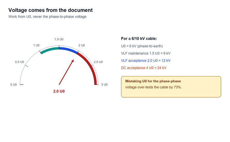
The second digit that matters is which test this is. Acceptance testing — new equipment, before energisation — runs at the full specified level. Maintenance testing — equipment that has been in service and is being returned — runs at a reduced level, because the insulation has already aged and the purpose is to confirm fitness, not to re-qualify. A common rule across standards is to reduce the acceptance voltage to about 75% for maintenance: a VLF maintenance test at 1.5 U0 is 75% of the 2.0 U0 acceptance value (IEEE 400.2-2013), and the same three-quarters logic appears in DC practice, where a retest after a repair is run at 80% of the original level (IEEE Std 95, 2002).
Worked numbers
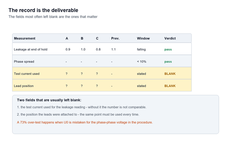
The arithmetic is easy once the U0 is known. A 6/10 kV cable has U0 of 6 kV — the phase-to-earth working voltage — so its VLF acceptance test at 2.0 U0 is 12 kV, and its maintenance test at 1.5 U0 is 9 kV. A 12/20 kV cable accepts 24 kV at 2.0 U0 and is maintained at 18 kV. Always work from U0, not from the phase-phase voltage; confusing the two over-tests the cable by 73% (IEC 60502-2:2014), against the U0 basis defined in that standard.
| Test object | Test | Typical voltage basis | Example |
|---|---|---|---|
| MV cable, acceptance | VLF sinusoidal | 2.0 U0 | 6/10 kV cable → 12 kV, 30 min |
| MV cable, maintenance | VLF sinusoidal | 1.5 U0 | 6/10 kV cable → 9 kV, 15 min |
| MV cable, DC acceptance | DC | per project spec, often 4 U0 | 6/10 kV cable → 24 kV |
| LV switchgear, routine | AC power frequency | 2 kV, 1 min | per IEC routine test practice |
| Rotating machine, DC | DC step test | per IEEE Std 95, 2002 | stepped to spec, watched per step |
| Repair retest | Either | 80% of acceptance (IEEE Std 95, 2002) | reduced by 20% (IEEE Std 95, 2002) |
Across commissioning job files for medium voltage cable circuits, the most common cause of an over-test was not the instrument but the convention: the DC number was quoted from the AC table without the conversion. A caution worth writing into every procedure: the hi pot test voltage for DC is often quoted as 1.7 times the equivalent AC rms value, because DC testing at the same peak stress needs the conversion. Mixing the two conventions without stating which one is in use is the single most common source of over-test in the field.
AC, DC and VLF: three ways to apply the stress
The test family is split by how the voltage is generated, and the split is not cosmetic. Each excitation stresses the insulation differently and suits different test objects.
DC excitation
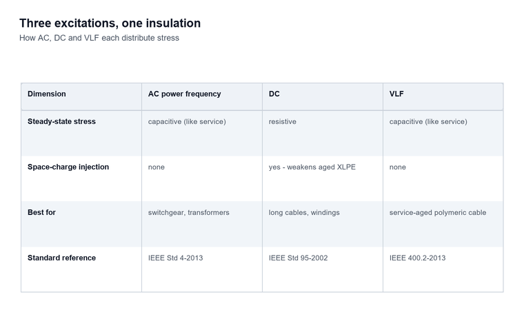
A DC hi pot set produces a smooth direct voltage, traditionally through a voltage multiplier, and modern DC high voltage generators deliver 60 kV to 300 kV at 2 mA to 10 mA with adjustable overvoltage protection set anywhere from roughly a third to the full output. The strengths are real: the test set is light for its voltage class because the charging power is small, the leakage current reading is clean and steady once the capacitive current has decayed, and the method suits long capacitance-heavy objects such as cables and large machine windings where an AC set of equivalent rating would need a small substation to drive.
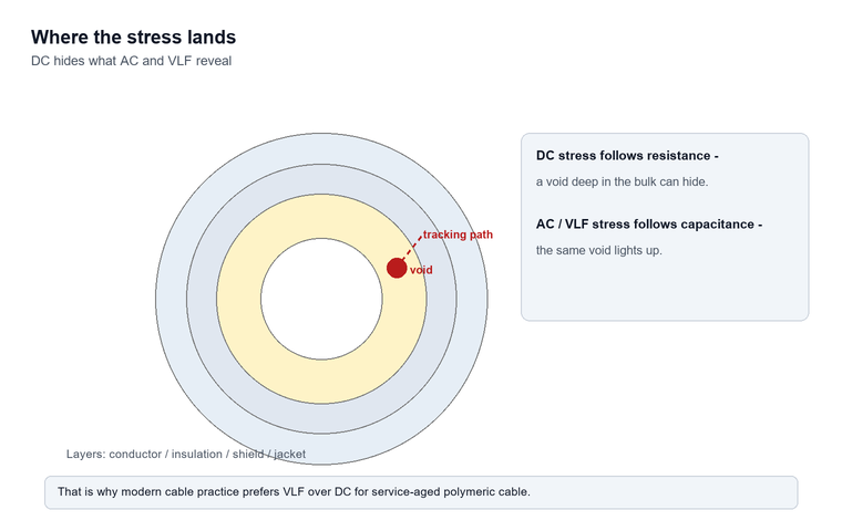
The weakness is the physics: a DC stress distributes across the insulation in proportion to resistance, while AC stress distributes in proportion to capacitance. Defects that sit in series layers can hide from a DC test that an AC test would find, and space charge injected into aged polymeric cable insulation by DC testing is the reason the practice fell out of favour for service-aged XLPE — IEEE 400.2-2013 and the cable standards now steer field testing of those cables toward VLF.
AC power frequency
An AC set applies the same kind of stress the insulation sees in service, at power frequency, and it is the natural choice for switchgear, busbars, instrument transformers and anything where the type test was AC. The cost is the power: the test set must supply the full capacitive charging current of the test object at test frequency, which is why AC sets for cable testing become large and heavy fast. For LV switchgear and controlgear the routine dielectric test is short and modest, and a compact power frequency tester with an output in the hundreds of volts to a few kilovolts covers the secondary circuits and LV panels; a dry type transformer high voltage generator or an impulse voltage generator covers the higher classes and the lightning impulse type tests.
VLF
Very low frequency testing runs the AC stress at 0.1 Hz instead of 50 or 60 Hz, which cuts the capacitive charging power by a factor of 500 and puts cable-sized test objects back within reach of a portable set. IEEE 400.2-2013 is the governing document, with sinusoidal, cosine-rectangular and damped AC waveforms all covered. The stress distribution across insulation layers is capacitive, like power frequency AC, so it finds the defects DC testing misses, and the field experience base on medium voltage cable is now deep enough that VLF is the default acceptance and maintenance method for service-aged polymeric cable in much of the industry. Diagnostic companions — tan delta testing on the same VLF source — add a graded condition assessment on top of the pass-or-fail proof.
Step-by-step test setup
The physical work of the test is dominated by preparation, and the electrical part is dominated by the ramp, and both halves deserve the same seriousness because most test failures trace back to a shortcut taken before the set was switched on. The sequence below is written for a DC or VLF cable test; the same structure carries to machine windings and switchgear with the obvious substitutions.
Isolate, prove dead, prepare the object
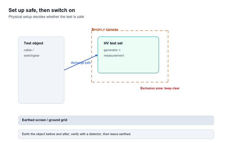
The cable is isolated at both ends, proved dead, earthed and then de-earthed for the test. The far end is opened, barriers and signage are placed, and the conductor ends are cleaned and spaced from earthed points. Metallic shields are bonded to the test set’s guard or earth terminal. Surge arresters, voltage transformers and anything else that cannot take the test voltage are disconnected, because the test will find them — destructively.
Connect, and decide the guard
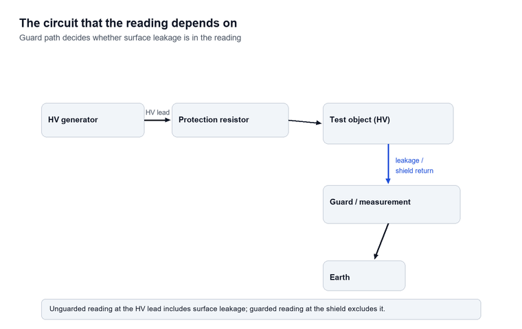
The high voltage lead runs to the conductor; the leakage measurement is taken either in the HV lead (unguarded, includes surface leakage across the terminations) or at the shield with a guard (excludes it). On a dry day with clean terminations the difference is small; in humid weather the unguarded reading can be dominated by surface tracking over the cable ends, and the guarded arrangement is what separates a surface problem from a bulk problem. The wiring of the test circuit, including the guard path and the return of the shield to the measurement terminal, is shown in the wiring diagram below.
Ramp, hold, watch
The voltage ramps at a controlled rate — fast enough to finish, slow enough that the capacitive charging current settles before the target is reached. On a DC test the ramp is followed by a hold period, commonly 15 minutes, during which the leakage current is expected to fall as absorption completes. The readings at fixed intervals are what the record is made of, not just the final number.
Discharge, then re-earth
After the test the cable holds the charge it was given, and on a DC test that charge is genuine and dangerous. Discharge through the set’s discharge path, verify with a voltage detector, then earth and leave earthed until the object is handed back. A cable that has just passed a 24 kV DC test is a hazard for minutes to hours afterwards, and the discharge procedure is part of the test, not an afterthought.
Reading the result: pass, fail and in-between
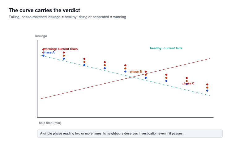
The obvious result — breakdown, the trip operates, the set announces the failure — is easy to read and hard to argue with. Everything else needs judgement, and the judgement hangs on the leakage-versus-time behaviour and the comparison between phases, which is why the recorded curve matters more than the final number.
What a pass looks like
Leakage current that rises with voltage during the ramp, then falls steadily through the hold period, levelling at a small stable value, is the signature of healthy insulation on a DC test. The three phases should read within a close band of each other; on a uniform cable circuit the spread between phases is small, and a single phase reading two or more times its neighbours deserves investigation even if it passes. A polarisation behaviour — leakage halving or better between the start and end of the hold — is the ideal shape.
What a warning looks like
Leakage that stays flat, or rises, during the hold period is the classic warning shape: the insulation is conducting more as the test continues, which points to moisture, contamination or a developing defect. Jumping leakage at a particular voltage during the step test marks the onset of partial discharge activity. A slow, steady climb during the hold is the shape that justifies extending the test or derating the equipment, and it is also the shape most often missed when the test is left unattended with only a final reading recorded — this is why the leakage-versus-time curve belongs in the record for every test, and why a rising trend on one phase against stable trends on the other two is the single most valuable diagnostic comparison the test produces.
What a failure looks like
Breakdown needs no interpretation, but it does need documentation: at what voltage, after how long, and what the leakage was doing in the minutes before. A failure at the full acceptance voltage in the first minutes of hold on new cable points to an installation fault at a termination or joint — and the fault location equipment that pairs with the test set will find it faster than visual inspection will.
Choosing among hi-pot testers suppliers
The commercial question — which set to buy — resolves into five checks, and the order matters less than the discipline of asking all five of every candidate.
- Voltage and current class against the real test objects. Work out the largest U0 you test, the excitation you need, and the capacitance you must charge; the output rating falls out of that arithmetic. A 60 kV, 2 mA DC set covers a lot of switchgear and machine work; long cable runs need the current or a move to VLF.
- Ramp control and measurement resolution. A set that can only slam to full output and read leakage in milliamps is half an instrument; the useful readings are microamps, and the useful control is a ramp with a defined slope.
- Protection and discharge. Adjustable overvoltage trip, overcurrent trip, and a built-in discharge path with an interlocked earth switch are the difference between an instrument and a hazard.
- Standards compliance in the manual, not the brochure. The set should state its compliance with the measurement requirements of IEEE Std 4-2013 — voltage division accuracy, ripple on DC output, and how the leakage measurement is made.
- Support and calibration trail. HV test sets drift like any HV instrument, and the supplier’s calibration service, documentation and spare multiplier stacks decide the ten-year cost, not the invoice.
When comparing hi-pot testers suppliers, ask each one to state, in writing, the test voltage and hold time they would recommend for your specific cable or machine list, and compare the answers against the standards quoted in this guide. Suppliers who tie their recommendation to a standard clause are easier to hold accountable than suppliers who quote a number without a source — and the same discipline applies to any insulation resistance test equipment purchased alongside it.
Limitations and boundaries
The test is a proof, and proofs have boundaries worth stating before someone assumes more than the test can deliver.
- A pass is not a condition grade. Equipment that passes may still be near the end of its life; the proof test finds the gross defects, and condition assessment needs the diagnostic family — insulation resistance trending, tan delta, partial discharge.
- DC testing misorders stress in layered insulation and injects space charge into aged polymers, which is why modern cable practice prefers VLF for field work; a DC pass on service-aged XLPE is weaker evidence than it looks.
- Surface conditions dominate unguarded readings. Humidity and contamination can triple the leakage without any bulk defect, and a test run in the wrong weather produces a warning that means nothing.
- The test consumes insulation life in a way the megohmmeter does not. Repeated full-level testing on the same object is a trade, and maintenance levels exist precisely to keep that trade sane.
- Energy at the terminals is dangerous, and stored charge on capacitive objects outlives the test. The discharge, verification and earthing procedure carries the same weight as the test voltage selection.
Frequently asked questions
What does hi pot stand for?
The term is short for high potential — the potential, or voltage, test. The full name appears in standards as a dielectric withstand test, and the shop names — pressure test, proof test — all refer to the same practice of applying an overvoltage to insulation that is out of service.
How is it different from an insulation resistance test?
The stress level and the question. An insulation resistance test applies hundreds of volts to a few kilovolts and measures how good the insulation is; the proof test applies several times the working voltage and asks whether the insulation survives. The two tests are complementary, and a sensible programme runs the low-stress measurement first and the proof test second, on the same terminals.
What test voltage should I use on a medium voltage cable?
Work from U0 and the test type. For a 6/10 kV cable under sinusoidal VLF, the acceptance test is 2.0 U0 — twelve kilovolts — for the duration in the project specification, and the maintenance test is 1.5 U0, nine kilovolts, at three-quarters of the acceptance stress (IEEE 400.2-2013). For DC testing the project specification usually sets 4 U0 for acceptance, and a retest after repair runs at 80% of that (IEEE Std 95, 2002). Never substitute the phase-to-phase voltage for U0; that over-tests the cable by 73%.
How long is the test held?
Long enough for the capacitive and absorption currents to settle so the leakage reading means something. On DC and VLF field tests the common hold is 15 minutes for maintenance tests and 15 to 30 minutes for acceptance tests on cable; machine windings are stepped and held per the applicable standard; LV switchgear routine tests hold for one minute. The duration is part of the specification, not a matter of preference.
Why is VLF used instead of DC on modern cables?
Two reasons. Stress distribution: VLF is still AC, so the voltage shares across insulation layers the way power frequency shares it, and defects that DC hides are revealed. Space charge: DC testing injects charge into aged polymeric insulation that can weaken it after the test, which is the reason IEEE 400.2-2013 and modern cable standards steer field testing of service-aged cable to VLF and damped AC methods.
What leakage current is acceptable?
There is no universal number, and any specification that quotes one without the test object’s size is suspect. The judgement is comparative: leakage should fall through the hold, the three phases should agree within a close band, and the value should be consistent with previous tests on the same equipment. A reading that doubles against last year’s test on the same object, or one phase at several times its neighbours, is the actionable signal — not an absolute microamp figure.
Can the test damage healthy equipment?
At the specified level and duration, the designed margin makes damage to healthy equipment unlikely — the test voltage is set below the level that would stress good insulation beyond its capability. Damage comes from over-test: the wrong convention for DC versus AC voltage, the wrong test on aged polymer cable, or repeating full acceptance levels on equipment that only needed a maintenance check. The margin exists, and the procedure protects it.
Conclusion
A hi pot test runs on a simple contract: apply the voltage the standard says, for the time the specification says, watch the leakage behave the way healthy insulation behaves, and record enough of the curve to make the judgement reviewable. The megohmmeter measures, the overvoltage set proves, and a testing programme that knows which question it is asking picks the right instrument first. Voltage comes from the document – U0, acceptance or maintenance, the reduction rules – and interpretation comes from the shape of the leakage curve and the comparison between phases. Set up cleanly, ramp slowly, watch the trend rather than the final number, and the proof test does exactly what it was built to do: find the insulation that would have failed in service, while it is still cheap to fix. To compare DC, VLF and power frequency sets against your cable and switchgear list, contact us with the voltage classes and circuit lengths you test.
References and technical sources
- IEEE, IEEE Guide for High-Voltage Direct-Current Measurements, IEEE Std 4-2013, which defines the measurement techniques, voltage division accuracy and terminology used across high voltage testing. ieee.org
- IEC, Power cables with extruded insulation and their accessories for rated voltages above 6 kV up to 30 kV, IEC 60502-2:2014, which sets the after-installation and routine test requirements for medium voltage cable systems. iec.ch
- IEEE, IEEE Guide for Field Testing of Shielded Power Cable Systems Using Very Low Frequency (VLF) (less than 1 Hz), IEEE 400.2-2013, the source document for VLF acceptance and maintenance voltage levels. ieee.org
- IEEE, IEEE Recommended Practice for Testing Insulation Resistance of Electric Machinery, IEEE Std 95-2002, covering DC testing practice on machine windings. ieee.org
- NETA, Acceptance Testing Specifications for Electrical Power Equipment and Systems, InterNational Electrical Testing Association, which sets the field acceptance and maintenance test voltage tables used across North American commissioning practice. netaworld.org