

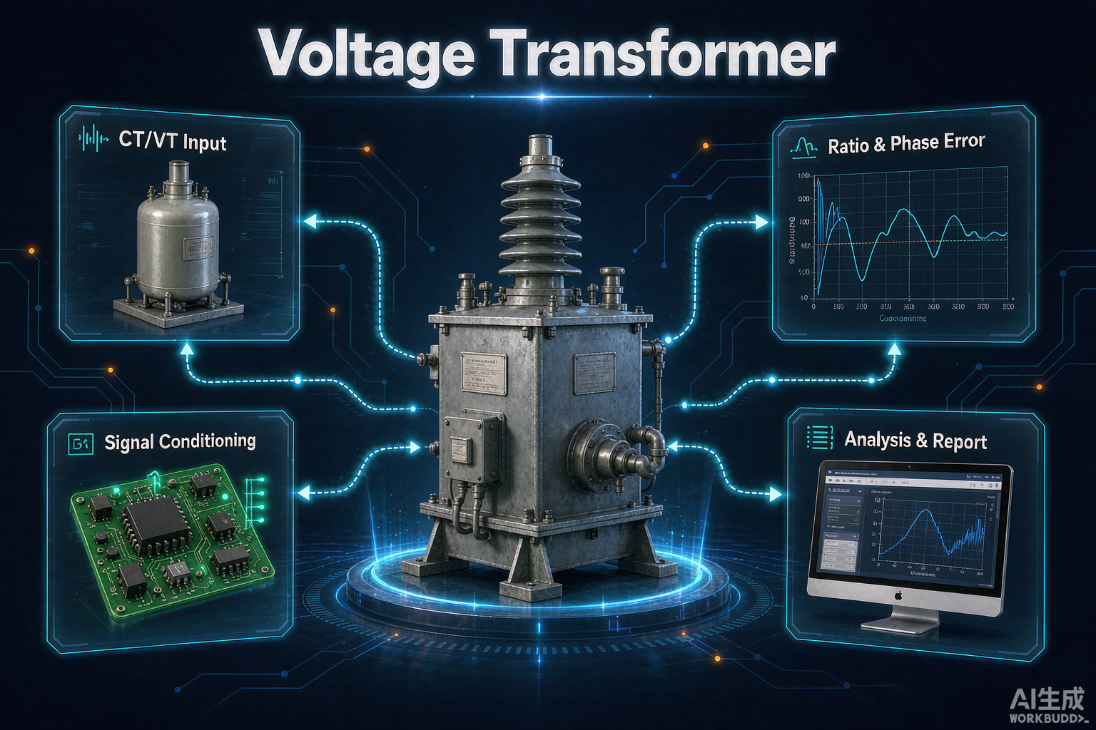
A voltage transformer is an instrument transformer that reproduces primary voltage at a fixed, safe and accurately known ratio so that measuring instruments and protective relays can operate on the secondary side. It is the quiet component of every substation: nobody notices it until a billing dispute, a distance relay misoperation or a burnt-out winding turns it into the most expensive two hundred kilograms on the yard.
Author: Leon Zhang — Power monitoring and testing equipment team, Baoding Houfeng Trading Co., Ltd., specifying instrument transformer test sets for substations and industrial plants
Technical review: reviewed against IEC 61869-1:2023, IEC 61869-3:2011 and IEEE C57.13-2016 before publication
Last updated: 20 October 2026
Key takeaways
- It steps primary voltage down to a standard secondary value, typically 110 V or 120 V, so meters and relays can measure a 33 kV bus without touching it.
- The nameplate ratio is not the ratio you get in service; ratio correction factor and phase displacement are what decide whether a metering core earns revenue accuracy.
- Accuracy classes are read as a pair in IEC practice and as a burden-qualified set in IEEE practice, and mixing the two notations is the most common specification error on international projects.
- Protection cores are chosen for transient behaviour and residual voltage generation, not for accuracy, because a distance relay needs a faithful replica during a fault, not a precise one at steady state.
- Ferroresonance is the failure mode that destroys inductive units, and it is prevented at design stage by damping, not by protection settings.
- Field acceptance rests on ratio, polarity, burden and insulation tests, and each of them is a five-minute check that catches a different class of defect.
Introduction
A voltage transformer is an instrument transformer that reproduces primary voltage at a fixed, safe and accurately known ratio so that measuring instruments and protective relays can operate on the secondary side. It is the quiet component of every substation: nobody notices it until a billing dispute, a distance relay misoperation or a burnt-out winding turns it into the most expensive two hundred kilograms on the yard.
This guide is written for the engineer who has to specify, accept or maintain these units rather than the one who designs the winding. It covers how the ratio and the error behave under real burden, how IEC and IEEE accuracy notations differ and where they conflict, how the secondary circuits that supply current transformers inside the same cubicle are affected by the choices made here, and the field tests that catch a defective unit before it reaches service. Every number in it is traceable to a published standard clause or to a manufacturer test record. Where practice varies between regions, the guide says so instead of picking a side.
What a voltage transformer actually does
The device measures voltage by converting it rather than by sensing it directly, and that conversion is where all of its value, all of its convenience and all of its error genuinely live, which is why a specification written around the conversion is far more reliable than one written around the nameplate alone. Primary winding connects across the phase and neutral, secondary winding feeds the meter or relay through a fused circuit, and the iron core couples the two with as little loss as the design allows.
The output is standardised so that instruments become interchangeable. IEC 61869-3:2011 specifies rated secondary voltages of 100 V, 110 V and 200 V for line-to-line connection, with 100/√3 V and 110/√3 V for phase-to-ground connection. North American practice in IEEE C57.13-2016 centres on 120 V and 69.3 V. A relay built for 110 V will not accept a 120 V signal without recalibration, which is why the secondary voltage is one of the first things to confirm when a specification crosses regions.
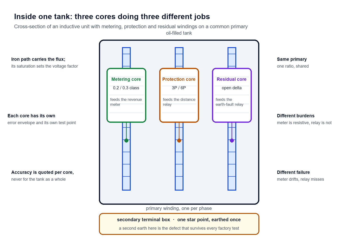
Three functions are normally packed into the same tank. A metering core delivers the small, highly accurate signal that feeds the revenue meter, and it is designed for accuracy at normal voltage with a nearly resistive burden. A protection core delivers a signal that stays faithful when voltage collapses during a fault, so it is designed for linearity and transient behaviour rather than for precision at rated point. A residual or open-delta winding sums the three phase voltages so that a solid single-phase ground fault produces a usable zero-sequence signal for the earth-fault relay.
Nameplate reading exercise
Take a typical 33 kV unit with a nameplate reading 33/√3 : 110/√3 : 110/3. The first ratio is the primary to the main secondary, giving a nominal ratio of 300:1, so 110 V on the secondary corresponds to 19.05 kV line-to-neutral, or 33 kV line-to-line. The third value, 110/3 V, is the residual winding: three such windings in open delta produce 110 V when one phase goes to zero during a solid ground fault, which is the voltage the earth-fault relay is set to expect.
Reading the same plate the other way is where mistakes happen. An engineer who treats 33/√3 as a line-to-line primary value will compute a ratio three times too large and then conclude the unit is defective when a ratio test disagrees with the calculation.
Ratio, ratio error and phase displacement
Three different quantities describe the same physical device, and confusing them with each other is the second most common source of specification error after the IEC and IEEE notation clash that this guide covers later. The nominal ratio is a nameplate arithmetic fact, the ratio correction factor is the multiplier applied to the nominal ratio to obtain the true ratio, and the phase displacement is the angle by which the secondary voltage leads or lags the primary voltage, expressed in minutes of arc.
A ratio test that measures 299.4:1 on a unit marked 300:1 is not a failed unit. That is a ratio error of -0.20%, which sits inside a 0.3 class limit of ±0.3% (IEC 61869-3:2011). The test result is normal, and a QA engineer who rejects the unit on the arithmetic difference alone will reject most of a healthy shipment.
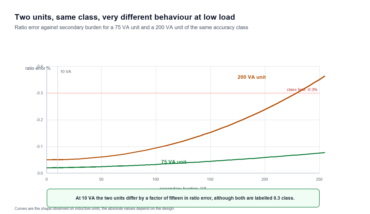
The two error components are not independent, and this matters when specifying. A unit designed to sit near the centre of the accuracy parallelogram at zero burden will drift outward as burden increases, because leakage reactance and winding resistance both grow with secondary current. Modern electronic meters and relays draw less than 1 VA each, so a unit rated at 200 VA may spend its whole service life in the bottom corner of its own accuracy envelope, where its error is quite different from the factory test point.
The practical implication is uncomfortable for procurement teams. Buying the highest burden rating available does not buy the best accuracy at the burden actually present. A unit rated at 75 VA often performs better at a 10 VA load than an otherwise identical unit rated at 200 VA, because the manufacturer pushed less copper and iron into designing for the extreme corner of the envelope.
The four numbers on a test certificate
| Quantity | Symbol | What it states | Typical value for a 0.3 class voltage transformer |
|---|---|---|---|
| Ratio correction factor | RCF | Multiplier on nominal ratio | 0.9970 to 1.0030 |
| Phase displacement | δ | Angle error in minutes | ±5 to ±40 min |
| Rated burden | VA | Secondary load at which accuracy is guaranteed | 12.5 to 400 VA |
| Accuracy class | — | Envelope containing both errors | 0.2, 0.3, 0.5, 0.6, 1.2, 3P, 6P |
A certificate that lists only the ratio passes nothing. The acceptance question is always whether both coordinates of the error point fall inside the envelope for the class and burden on the nameplate.
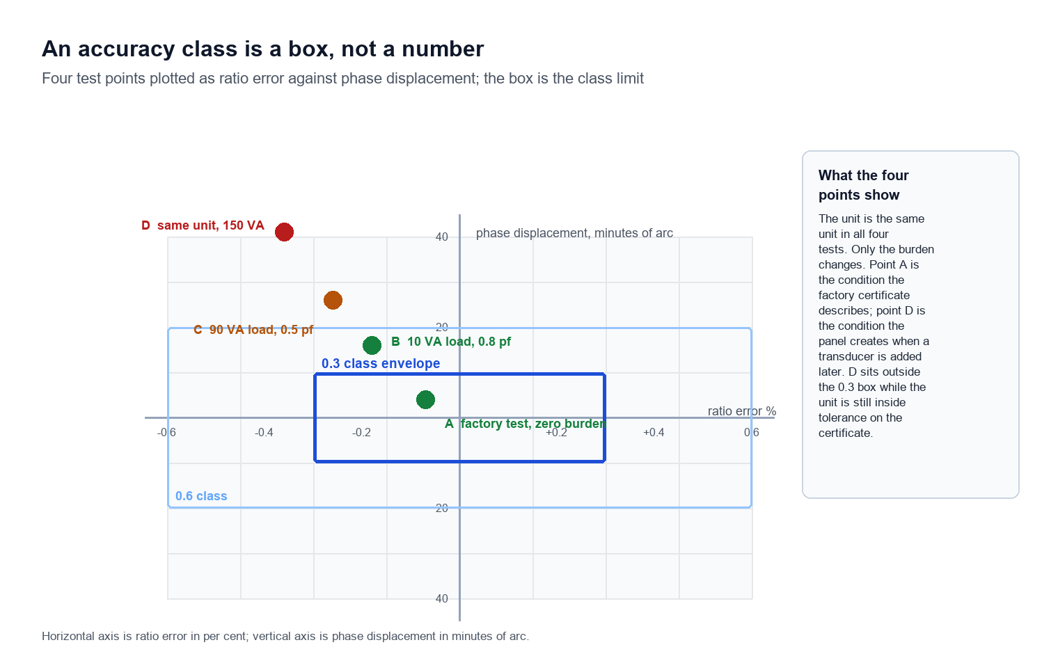
Workshop note. On the test bench, the fastest way to expose a burden-related error is to run the ratio test twice: once unloaded, once with a resistive load box set to the nameplate VA. If the ratio error moves by more than a third of the class limit between the two runs, the unit is dimensioned for a corner of its envelope that the actual panel does not occupy, and the certificate figure is not the figure the site will see.
Wiring: where the secondary circuits meet the current transformers inside the same panel
This section is about the part of the design that no single-device guide covers, because the voltage and current circuits share a cubicle, a terminal block and often a common multi-core cable. A protection relay that receives a correct voltage signal and a mis-wired current signal will still misoperate, and the fault will be attributed to the relay rather than to the wiring.
The shared reference point is the star point. All three phase secondaries are star-connected with the neutral solidly earthed at one point only, normally at the transformer terminal box. Every relay, meter and transducer in the scheme picks up its neutral from that same point, and a second earth anywhere in the run creates a parallel path through the station earth grid that carries circulating current and corrupts the measured phase angle.
When the current transformers sit in the same panel, the same rule applies in mirror image: their secondaries are star-connected and earthed at one point, usually on the relay side of the panel, and the two earth points must not be bonded together inside the cubicle. Bonding them looks tidy and creates a loop. That loop injects the potential difference between the two earth points, which during a fault can reach tens of volts, directly into both measuring circuits.
Polarity is the other shared trap. Voltage and current polarity marks are both P1/S1 or dot-marked, and a scheme that reverses one and not the other inverts the measured power direction. A directional overcurrent relay seeing reversed voltage polarity will treat a forward fault as a reverse fault and block the trip, which is a failure mode that only appears during a real fault and is therefore the most expensive kind to discover late.
Practical checks that catch this class of defect before commissioning:
- Inject a known three-phase voltage set and confirm phase rotation at the relay terminals with a phase sequence meter, not with a multimeter.
- Confirm the secondary neutral is earthed at exactly one point by measuring resistance to the earth bar with the relay disconnected.
- With the current circuit short-circuited and earthed at its own single point, inject current and voltage together and verify that the measured power angle matches the expected load angle.
- Record the terminal numbers at both ends of every multi-core cable and keep the record with the relay test report, because the next fault investigation will need it.
Why the shared neutral causes silent errors
A single-phase volt drop along a shared neutral conductor is small in normal operation and grows during a fault, exactly when the protection has to decide. In a scheme where three phase voltages and a residual voltage all return through a common neutral core, the return current from the residual winding flows through the same conductor that the phase measurement is referenced to. The phase voltage then contains an error proportional to the residual current, and the error appears as an angle shift rather than a magnitude change, so it does not show up on a routine voltage check.
The remedy is either a separate neutral core for the residual circuit, or a residual winding measured by differential connection that does not depend on the common return. Both are drawing-board decisions. After commissioning, the only practical control is to record the measured phase angles at known load and compare them against the same measurement after any wiring modification.
Terminal numbering in a mixed cubicle
| Terminal block | Circuit | Earth reference | Common mistake |
|---|---|---|---|
| 1 to 4 | Phase voltage 1L1 | Star point at terminal box | Second earth on relay panel |
| 5 to 8 | Phase voltage 1L2 | Same star point | Phase and neutral swapped |
| 9 to 12 | Phase voltage 1L3 | Same star point | Rotation reversed at cable head |
| 13 to 14 | Residual voltage | Open delta, floating | Bonded to star point |
| 15 to 18 | Phase current | Current transformer star point | Both ends earthed |
Voltage transformer vs CT transformer: what changes when you swap roles
Engineers often reach for a single mental model covering both types of instrument transformer, and that model works well enough for most routine work until the two types are asked to do something it does not cover at all. A ct transformer is built to deliver a defined secondary current proportional to primary current, and its accuracy is quoted in a way that assumes a low-impedance burden, while the voltage type delivers a defined secondary voltage and assumes a high-impedance burden instead.
The core difference is what happens on a short circuit. A current transformer with an open secondary develops a dangerous voltage because the primary current has nowhere to go, which is why its secondary is always shorted before the circuit is broken. A unit with a shorted secondary simply draws excessive current and overheats, which is why its secondary is always protected by fuses or a miniature circuit breaker and never shorted deliberately.
The accuracy ratings follow the same asymmetry. A current device is rated by composite error at a defined accuracy limit factor, because saturation under fault current is its characteristic failure. A voltage device is rated by an error envelope at a defined burden, because its characteristic failure is phase shift and ratio drift as the burden changes. Applying a current transformer accuracy limit factor to a voltage device, or a voltage accuracy class to a current device, produces a specification that no manufacturer can meet and no test can verify.
Side-by-side rating comparison
| Rating | Voltage device | Current device | Notes |
|---|---|---|---|
| Secondary output | 100 to 120 V | 1 A or 5 A | Fixed by instrument design |
| Burden unit | VA at defined power factor | VA at defined power factor | Same unit, opposite sensitivity |
| Accuracy basis | RCF and phase angle envelope | Composite error at ALF | Not comparable |
| Failure with open secondary | Low output, no danger | Very high voltage, lethal | Drives shorting practice |
| Failure with shorted secondary | Overcurrent, overheating | Normal operation | Drives fuse practice |
| Protection class example | 3P, 6P | 5P10, 5P20 | P denotes protection |
| Saturation behaviour | Saturates at the voltage factor | Saturates at the accuracy limit factor | Distance relay setting depends on it |
The comparison table is the fastest way to explain the difference to a procurement colleague who has been told that both are simply transformers, and it also shows why the two datasheets cannot be compared column by column.
How the three accuracy notations actually differ
IEC and IEEE describe the same physics with different vocabularies, and a specification written in one convention then reviewed in the other will appear wrong even when the equipment is correct. The International Electrotechnical Commission system, as set out in IEC 61869-3:2011, writes accuracy as a class number followed by a power factor or a range, for example 0.2 for a metering class or 3P for a protection class. The Institute of Electrical and Electronics Engineers system, set out in IEEE C57.13-2016, writes accuracy as a class number followed by burden designations, for example 0.3WXMYZ.
The IEEE burden letters are not arbitrary. Each letter denotes a standard volt-ampere load and a standard power factor, and the set of letters attached to a class states the burdens over which that class is guaranteed. A single letter implies all lower burdens as well, so 0.3Z and 0.3WXYZ describe the same unit.
| IEEE designation | Burden | Power factor | Typical use |
|---|---|---|---|
| W | 12.5 VA | 0.10 | Solid-state meter only |
| X | 25 VA | 0.70 | Basic metering |
| M | 35 VA | 0.20 | Special utility designation |
| Y | 75 VA | 0.85 | Standard metering |
| Z | 200 VA | 0.85 | Multi-tap metering |
| ZZ | 400 VA | 0.85 | Rare, heavy burden |
The IEC metering classes are 0.1, 0.2, 0.5 and 1.0 for the standard series, with 0.2 or 0.5 covering almost all revenue applications in medium voltage networks. The protection classes are 3P and 6P, where the number denotes the permissible composite error at the rated voltage factor.
Where the two systems meet, three conflicts recur on international projects:
- Class numbering. A class 0.2 unit under the IEC notation is not the same envelope as a class 0.3 unit under the IEEE notation, and neither maps cleanly to the other. Converting by arithmetic, for example treating 0.3 as a relaxed 0.2, produces a specification that is out of tolerance in one system and over-priced in the other.
- Voltage factor. IEC specifies a rated voltage factor of 1.2 continuous and 1.9 for 30 seconds on effectively earthed systems, while IEEE specifies 1.1 and 1.9. A unit designed to one and installed where the other is expected will be operated closer to saturation than intended.
- Burden power factor. IEEE standard burdens are defined at a specified power factor per letter, from 0.10 to 0.85, while IEC states the burden range and lets the purchaser define the power factor. Two units both rated 0.2 class can therefore have been tested under quite different load angles.
Accuracy class is an envelope, not a number
The number on the nameplate is a boundary, and the boundary is a parallelogram in the plane defined by ratio correction factor and phase angle, not a single tolerance on a single quantity. Understanding the shape explains several behaviours that otherwise look like manufacturing variation.
At zero burden, the error point sits near one corner of the parallelogram. As burden increases at the specified power factor, the point travels in a straight line toward the opposite corner, because both the resistive drop and the reactive drop grow in proportion to secondary current. The manufacturer designs the winding so that the line stays inside the envelope for the whole rated burden range, which means the two ends of the line are pushed as close to the boundary as the design allows.
This has a direct consequence for anyone specifying a unit for a load far below its rating. The error at light load is not the average of the two corner values; it is wherever the design placed the zero-burden point, and manufacturers deliberately place it near the boundary to save material. A unit specified at 200 VA and operated at 5 VA may therefore show worse accuracy than its class suggests at the point where it is actually used.
The practical countermeasure is to state the operating burden in the specification and ask for the test certificate at that burden as well as at the rated burden. Manufacturers hold two measured points, zero and full rated burden, and interpolate linearly between them; a purchaser who asks for the interpolated value at the real load gets a number that is defensible in an acceptance dispute.
Where the error point travels
| Operating point | Position in envelope | Effect on a revenue meter |
|---|---|---|
| Zero burden | Near lower boundary | Best ratio, worst phase angle |
| Half rated burden | Midpoint of load line | Balanced error point |
| Rated burden | Near upper boundary | Worst ratio, best phase angle |
| Beyond rated burden | Outside envelope | Class no longer valid |
Protection cores: residual voltage and transient response
A protection core is not a less accurate metering core, and treating it as one produces a design that is both expensive and less secure at the moment it is needed. Its job is to reproduce the primary voltage faithfully during the two seconds that matter, including the part of the fault where the voltage on the faulted phase collapses to zero and the healthy phases rise.
The 3P and 6P classes in IEC 61869-3:2011 define composite error at the rated voltage factor rather than at rated voltage, because a unit that saturates at 1.2 times rated voltage cannot serve a protection function at all. The core is dimensioned so that it stays linear up to the voltage factor expected during a ground fault on the particular earthing system, which for an effectively earthed 132 kV system means the voltage on the healthy phases rises to the line-to-line value.
The residual winding is the protection function that most often fails quietly. Three star-connected secondaries with their neutrals brought out and the residual circuit formed by the sum of the three phase voltages will produce a correct zero-sequence signal only if the three cores are matched. An unbalanced set produces a standing residual voltage that the earth-fault relay must be set above, which desensitises the protection exactly where it is needed most.
An open-delta residual winding avoids the matching problem entirely, because each of the three windings is loaded only by the residual relay and the signal is generated by magnetic summation instead of by three independent measurements. The cost is a fourth winding and a larger tank, and that is why the choice is made at specification stage rather than at maintenance.
Transient response is the second protection characteristic that a metering-style specification misses. A capacitive unit with an intermediate electromagnetic stage stores energy in its divider and releases it with a time constant of several milliseconds, which can invert the apparent voltage direction during the first cycle of a close-in fault. Distance protection that relies on a polarised voltage signal can then see a forward fault as a reverse fault. The TVR class, defined in the capacitive part of the instrument transformer family, exists precisely to describe this behaviour, and units intended for distance protection should be specified with a TVR class rather than with an accuracy class alone.
Ferroresonance: the failure mode that kills voltage transformers
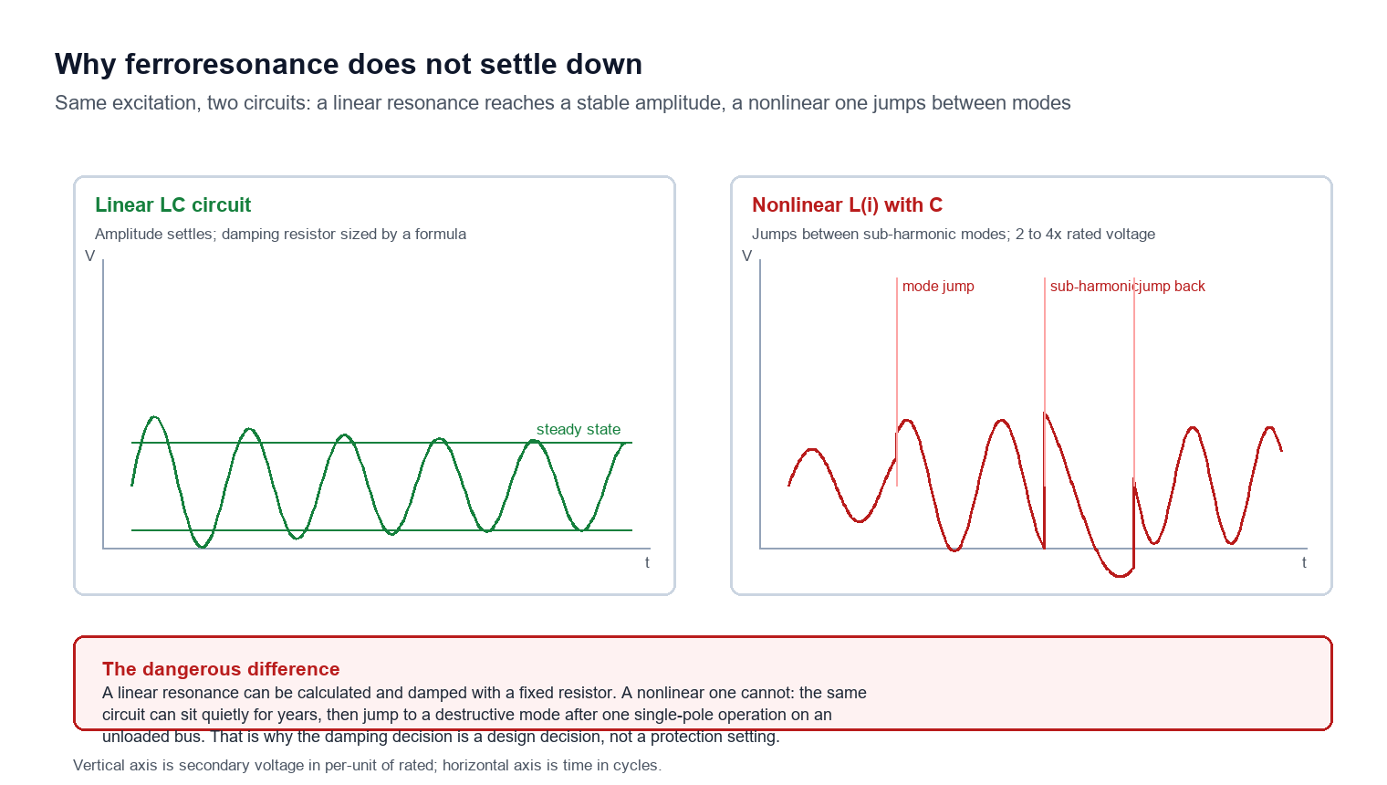
Ferroresonance is a resonance between the nonlinear magnetising inductance of an iron core and the capacitance of the surrounding system, and it is the single failure mode that destroys more inductive units than any dielectric defect. The nonlinearity is the dangerous part: unlike a linear resonant circuit, the oscillation does not settle into a stable amplitude but can jump between sub-harmonic modes and reach two to four times rated voltage without decaying.
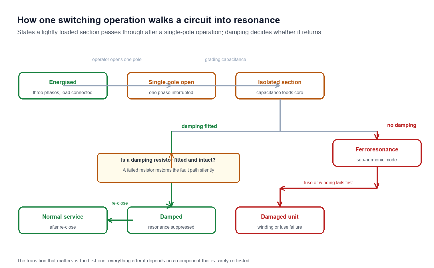
The classic trigger is a single-pole switching event on a lightly loaded or unloaded bus. When one phase opens while the other two remain energised, the capacitance of the de-energised section forms a series circuit with the magnetising inductance of the unit still connected, and if the circuit parameters fall in the resonant band the oscillation builds. The same mechanism appears during a single-phase ground fault on an isolated neutral system, and during the moment when a circuit breaker’s grading capacitance feeds a disconnected bus.
Two design responses exist, and they are not equivalent. The first is a damping resistor across the open-delta residual winding, sized to dissipate the resonant energy. Practice in medium voltage networks places the value in the range of roughly 10 to 100 ohms for systems at 35 kV and below, with the upper bound set by the overload that a persistent single-phase ground fault imposes on the open-delta winding and the lower bound set by the amount of damping required. A resistor that is too small protects against resonance and overloads during a sustained fault; one that is too large fails to damp. Nonlinear resistors solve the conflict at higher cost.
The second response is the capacitive divider unit, which replaces the magnetising path with a capacitive one and removes the nonlinear inductance from the resonant circuit entirely. That is why capacitive units dominate above 110 kV, where the inductive design would need an impractically large core to stay linear at the voltage factor. The trade is that the capacitive unit has its own transient behaviour, dealt with in the previous section, and its own damping requirement inside the intermediate stage.
Damping options compared
| Approach | Resonance risk | Cost | Where it is used |
|---|---|---|---|
| Inductive, undamped | High | Lowest | Not acceptable on isolated-neutral systems |
| Inductive with fixed damping resistor | Low | Low | Most 35 kV and below installations |
| Inductive with nonlinear damping | Low | Medium | Where sustained ground faults are expected |
| Capacitive divider with internal damping | Very low | Highest | 110 kV and above |
On retrofit projects in existing 10 kV and 35 kV switchrooms, the single most reliable predictor of a ferroresonance incident is not the unit type but the switching arrangement: an unloaded bus fed through a single-pole device with no damping fitted anywhere on the section. Checking that arrangement on the drawing before the unit is ordered costs fifteen minutes and replaces a failure investigation later.
Field tests that actually catch a bad unit
Acceptance testing at site is not a re-run of the factory routine test, and treating it as though it were wastes a site visit, produces a tidy report and still leaves the expensive classes of failure undetected until the first fault. The field tests exist to catch the six things that happen between the factory gate and the switchyard: transit damage, moisture ingress, a wrong ratio at a tap, reversed polarity, insulation degradation and a burden mismatch with the instruments actually connected.
Ratio and polarity together take about five minutes with a variable-voltage source and a reference meter, and they catch the most expensive class of error because a reversed polarity unit passes every other test. The accepted method applies a reduced voltage to the primary, reads the secondary with a meter whose own accuracy is at least a factor of four better than the unit under test, and compares the measured ratio and the phase angle with the certificate.
Insulation resistance and power factor tests follow, and the interpretation is where engineers most often misjudge. A primary-to-secondary reading in the gigohm range at 5 kV is normal for a dry unit and not evidence of quality, while a reading that has halved since the previous test is a trend worth investigating even if it is still high. The absolute value tells you whether the unit is safe to energise; the trend tells you whether it will still be safe in five years.
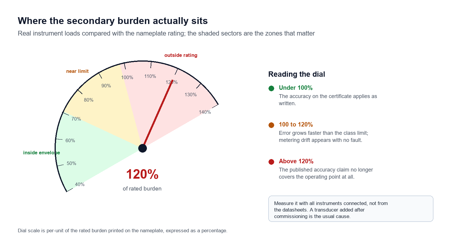
Burden measurement is the test most often skipped and the one that explains most unexplained metering drift. Connecting a burden meter across the secondary with all instruments in circuit gives the actual volt-amperes at the actual power factor. A unit rated at 75 VA that is carrying 90 VA because someone added a transducer after commissioning is operating outside its validated envelope, and no amount of instrument calibration will recover the accuracy.
Test order and what each catches
| Test | Instrument | Catches | Typical duration |
|---|---|---|---|
| Ratio and phase angle | Variable source and reference meter | Transit damage, tap error | 5 to 10 minutes |
| Polarity | DC pulse or AC comparison | Reversed winding | 2 minutes |
| Insulation resistance | Insulation tester at 5 kV | Moisture, contamination | 3 minutes |
| Power factor or tan delta | Dielectric loss set | Ageing insulation | 15 minutes |
| Burden | Burden meter or power analyser | Overloaded secondary | 5 minutes |
| Winding resistance | Micro-ohmmeter | Loose connection, broken strand | 5 minutes |
Limitations and boundaries
This guide describes inductive and capacitive designs for medium and high voltage systems from 15 Hz to 400 Hz, and five limitations should be stated plainly because they are where the advice stops applying and where a reader could otherwise over-read it.
The first limitation is that local standards override the international ones described here. A unit built to a national standard derived from IEC may carry the same class number with a different permissible error, and the nameplate governs. Where a project specifies a national standard, the acceptance criteria must be taken from that document and not from this page.
The second limitation is that accuracy statements cannot mean anything without the operating burden. Every figure in this guide assumes the unit is working inside its rated burden at the specified power factor, and a unit operated outside that envelope is outside the scope of any published accuracy claim, including the manufacturer’s own.
The third is that the field tests listed here confirm a unit is serviceable, not that it is calibrated. Traceable calibration of reference-grade units is a laboratory activity with an accredited chain of comparison, and a site test with a portable set demonstrates fitness for service rather than metrological status.
The fourth is that a ratio and polarity test cannot detect a partially shorted turn in the primary. A shorted turn changes the ratio by a fraction well inside the tolerance band of the test set, so the unit passes while its error has moved. Only a turn-ratio test at higher resolution, or a comparison against a known reference unit at more than one voltage point, will reveal it.
The fifth is cost. A unit with a 0.2 metering class and a 6P protection core in the same tank costs roughly twice a single-core unit of the same rating, and the premium buys nothing if the site has no revenue metering. Specifying dual cores where one is not required is the most common way to overspend on this equipment.
Frequently asked questions
The seven questions below are the ones that arrive most often during specification review, factory acceptance and site commissioning, and each answer is written to be usable on its own without reading the rest of the guide first.
What is the difference between a voltage transformer and a potential transformer?
The terms describe the same device, and the difference is regional usage rather than physics. Potential transformer is the older North American term and still appears on IEEE nameplates and in utility specifications, while voltage transformer is the term used in IEC 61869-3:2011 and in most international procurement documents. Neither term covers capacitive units, which are normally called capacitor voltage transformers and standardised separately.
Why does my unit show 299.4 to 1 when the nameplate says 300 to 1?
That reading is a ratio error of -0.20%, which is normal for a 0.3 class unit and well inside the ±0.3% limit (IEC 61869-3:2011). The nameplate ratio is a nominal arithmetic value, not a measurement result. A unit that measured exactly 300 to 1 would be a curiosity rather than a quality indicator, because manufacturers design the winding to sit inside the accuracy envelope rather than on the nominal point.
Can I use one unit for both metering and protection?
It is done in practice with a two-core design, one core optimised for accuracy at rated voltage and one for linearity at the voltage factor, but a single core cannot serve both well. The metering core is designed around a specific burden and a specific power factor, and the protection core around composite error during a fault. Where both functions are required, specify two cores and check that each carries its own accuracy rating on the nameplate.
How do I know whether my unit has a ferroresonance problem?
The signature is a persistent overvoltage or a distorted waveform on a de-energised or lightly loaded section, often after a single-pole switching operation, together with unexplained fuse operations or heating in the residual winding. The diagnostic step is to check whether the residual winding has a damping resistor connected and whether that resistor is still intact, because a failed damping resistor restores the original fault mechanism without any other symptom.
What burden should I specify when I do not know the connected load?
Measure it rather than guess, and specify the next standard burden above the measured value. Modern electronic instruments draw well under 1 VA each, so a typical relay panel presents a fraction of a standard burden, and specifying the largest available burden buys cost without buying accuracy. If the load cannot be measured before purchase, specify the smallest standard burden that covers the design with margin and re-check at commissioning.
Is a capacitive unit always better above 110 kV?
Above 110 kV the capacitive design is usually the only practical option, because an inductive core large enough to stay linear at the voltage factor becomes uneconomical to insulate. Below that voltage the choice depends on the application: a capacitive unit adds carrier coupling capability and lower weight but brings its own transient response and damping requirements, so for pure metering duty on a medium voltage bus the inductive unit is usually simpler.
How often should the unit be tested after commissioning?
Follow local maintenance rules first, then treat the insulation trend as the deciding input rather than the calendar. A first test at commissioning, a second within three years to establish the trend, and subsequent tests at intervals set by the observed rate of change gives better information than a fixed five-year cycle, because the absolute insulation value rarely predicts failure while a consistent downward trend does.
Conclusion
The device is simple in principle and unforgiving in detail, and almost every field argument about a voltage transformer can be settled by four numbers recorded at commissioning rather than by opinion. The ratio is arithmetic, the accuracy is an envelope rather than a number, the IEC and IEEE notations describe the same envelope in incompatible vocabularies, and the protection function depends on behaviour during a fault rather than on precision at rated point. Getting those four things right at specification stage costs nothing, while discovering them at commissioning costs a site visit and sometimes a replacement unit.
For engineers buying or accepting these devices, the useful discipline is to record four numbers on every unit ordered: the nominal ratio, the ratio correction factor, the burden at which it was measured, and the insulation reading. Those four points turn every later dispute into an arithmetic question, and every later maintenance decision into a trend rather than a guess.
Baoding Houfeng supplies instrument transformer test sets for ratio, polarity, burden and dielectric loss measurement, alongside the reference units used to verify them. Details of the full range are on the instrument transformer tester category page, and specifications for individual sets are listed under instrument transformer analyzers. If you are specifying a test set for a fleet with a mix of IEC and IEEE nameplates, contact us with the nameplate details and we will tell you which set covers both conventions without a second instrument.
References and technical sources
- IEC 61869-1:2023, Instrument transformers — Part 1: General requirements, International Electrotechnical Commission, edition 2.0, 2023. webstore.iec.ch/en/publication/34049
- IEC 61869-3:2011, Instrument transformers — Part 3: Additional requirements for inductive voltage transformers, International Electrotechnical Commission, edition 1.0, 2011. webstore.iec.ch/publication/6051
- IEC 61869-5:2011, Instrument transformers — Part 5: Additional requirements for capacitor voltage transformers, International Electrotechnical Commission, edition 1.0, 2011. webstore.iec.ch
- IEEE C57.13-2016, IEEE Standard Requirements for Instrument Transformers, IEEE Standards Association. standards.ieee.org
- IEC 61869-2:2012, Instrument transformers — Part 2: Additional requirements for current transformers, International Electrotechnical Commission, edition 1.0, 2012. webstore.iec.ch