

A ground resistance tester is an instrument that injects a current into the earth and measures the resulting potential at a second point, so that the resistance of an electrode, a grid or a bonding connection becomes a number rather than an assumption, and the number is only meaningful when the test method, the probe geometry and the soil around them are known. The choice that decides most purchases is not the range or the display; it is which of the three measurement principles the site actually permits, because a clamp instrument and a four-terminal instrument answer different questions and neither substitutes for the other.
Author: Leon Zhang — Power monitoring and testing equipment team, Baoding Houfeng Trading Co., Ltd., specifying earthing and insulation instruments for substations, plants and commissioning contractors
Technical review: this guide passed editorial review and was checked against IEC 61557-5:2007, IEEE Std 81-2012 and IEEE Std 80-2013 before publication
Last updated: 23 October 2026
Key takeaways
- The three measurement principles are not interchangeable. A two-, three- or four-terminal instrument derives resistance from an injected current and a measured potential difference using its own auxiliary probes; a clamp instrument measures a current circulating in a closed loop and reports the loop resistance, which includes every bond in series and every parallel path.
- Fall-of-potential with a probe at 61.8% of the current-electrode distance is the reference method (IEEE Std 81-2012), and its result is only accepted when the measured curve is flat around that point. A single reading taken with the probes at the wrong spacing produces a plausible-looking number with no basis.
- Soil resistivity is measured, not assumed. The four-electrode method gives a resistivity that varies with probe spacing, and the variation with depth is the information that decides whether one rod is enough or a grid is required.
- Ground potential rise, not kilohm readings, is what the standards constrain. IEEE Std 80-2013 sets tolerable touch and step voltages from body weight, fault clearing time and surface layer resistivity, and an electrode that reads 1 Ω can still fail those limits at a high fault current.
- A clamp instrument is the right tool for continuity and for parallel-rod loops and the wrong tool for a single isolated rod, where no return path exists and the reading is dominated by whatever else is bonded.
- Seasonal variation, cable routing and probe contact resistance account for most disagreements between two surveys of the same installation, which is why the soil condition, the probe depth and the line direction belong on the report.
Introduction
An earth electrode is the only part of an electrical installation that is installed, covered over and then effectively forgotten until something fails, which makes the instrument used to verify it unusually important: the test is often the last chance to find that a rod was driven into gravel, that a bond was left loose, or that the grid drawing shows four meshes where three were laid. This guide is written around that situation, and around the procurement decision that precedes it.
The sections below cover what each measurement principle measures, how to choose between a two-, three-, four-terminal and clamp instrument, how probe spacings follow from the electrode size, and how soil resistivity is read. They then turn to the safety limits that govern a substation rather than a remembered rule of thumb, and to where the measurements stop being trustworthy. Every threshold quoted is traceable to a published clause.
What a ground resistance tester measures
A ground resistance tester measures the ratio of a potential difference to an injected current at a defined pair of points, and the resistance it reports is therefore the resistance of whatever path the current actually took rather than the resistance of the rod in isolation. IEC 61557-5:2007 defines the measurement for earth electrode resistance testers and requires the test current to be alternating within a band from 15 Hz to 2 kHz, chosen so that the measurement is not corrupted by power-frequency earth currents or by the direct voltages that polarise an electrode.
That frequency choice explains why a multimeter cannot do the job. A direct measurement across a rod and a remote point carries the electrode’s polarisation potential, the galvanic voltage between dissimilar buried metals, and any stray current flowing in the soil, all in series with the quantity of interest. An alternating test current at a frequency offset from the supply, demodulated by a synchronous detector, separates the instrument’s own signal from those terms — which is why the better instruments offer several test frequencies and an automatic frequency selection mode rather than one.
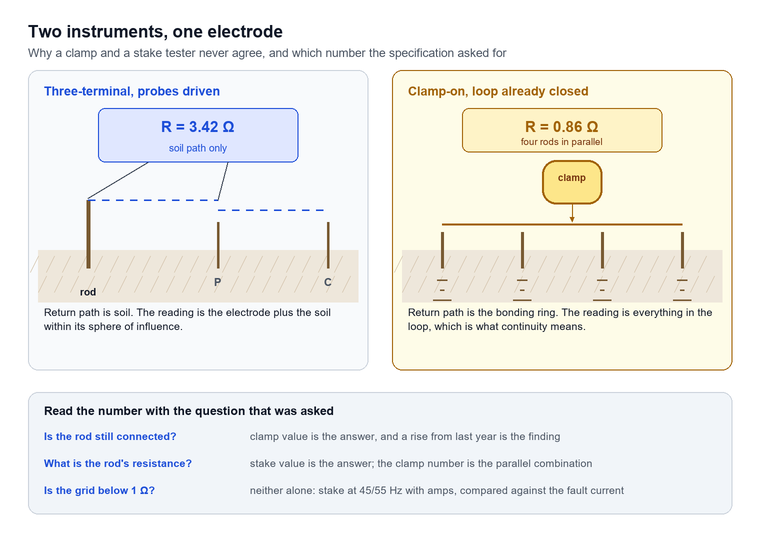
The second thing the instrument defines is the reference. Resistance is meaningless without naming the second point, and every method differs only in where that second point is and how the return path is completed. Three-terminal and four-terminal methods use two auxiliary earth electrodes driven by the operator, so the return path is soil. The clamp method uses the installation itself as the return path, so the measured value includes every parallel earth and every bonding conductor in the loop.
| Method | Terminals | Return path | What the reading includes |
|---|---|---|---|
| Two-terminal | 2 | A known good earth, such as the supply earth or a metal structure | The electrode under test plus the reference earth plus the connecting lead |
| Three-terminal | 3 | Current probe and potential probe driven into soil | The electrode under test only, provided the probes are far enough away |
| Four-terminal | 4 | Two current probes and two potential probes | The electrode under test, with lead and contact resistance cancelled by the separate potential circuit |
| Clamp-on | None | The installation’s own earthing and bonding conductors | Every parallel path in the loop, which is why the reading is always lower than the isolated value |
| Soil resistivity | 4 | Four equally spaced probes in a line | Not an electrode at all, but the resistivity of the soil between the probes |
Why the four-terminal method removes the lead resistance
A three-terminal instrument measures the total circuit, which includes the resistance of the lead to the electrode under test, the contact resistance between the clip and the electrode, and the resistance of the electrode itself. Those terms are usually small against a soil resistance of a few ohms, and they stop being small when the electrode is a bonding connection of a few milliohms or when the test lead is a hundred metres long on a large grid.
The four-terminal arrangement puts the current and the potential on separate pairs of leads, so the only current flowing in the potential leads is the input current of a high-impedance voltmeter, which is negligible. The lead resistance drops out of the result entirely. This is the reason a four-terminal instrument is specified for a substation grid and for equipotential bonding, while a three-terminal instrument is adequate for a single distribution rod.
Direct, frequency-selective and clamp readings
Direct readings use one test frequency with a filter. Frequency-selective readings sweep or select among several frequencies to find one where the interference from the surrounding network is lowest, and the specification sheet usually lists them as fixed values such as 94, 105, 111 and 128 Hz. Clamp readings use a winding around the conductor to induce a current at a defined frequency and a second winding to detect it, with the ratio between them giving the loop impedance.
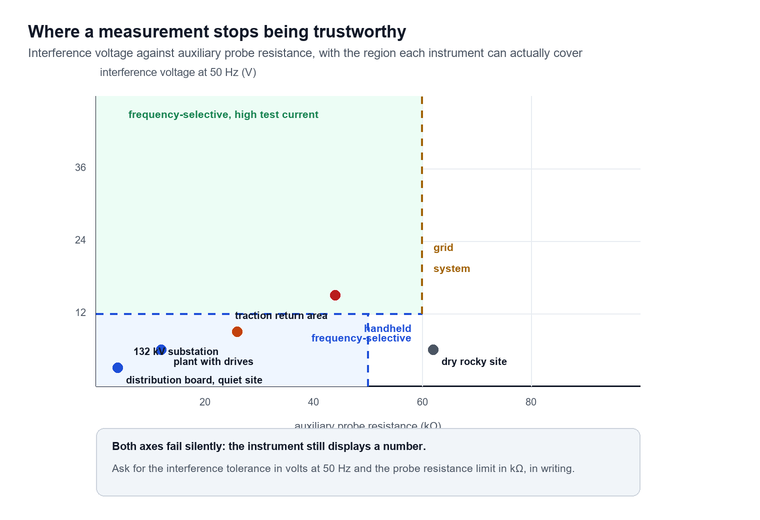
The distinction matters at a substation, where the earth under test carries a stray current from the supply system that can be several volts of 50 Hz across the electrode. An instrument with only a direct reading will report that voltage as resistance, and the error can be an order of magnitude. A frequency-selective instrument rejects the 50 Hz component by design, and the specification to look for is the maximum interference voltage it will tolerate, not the resolution.
| Reading mode | What the instrument does | Where it holds | Where it fails |
|---|---|---|---|
| Direct | One frequency with a band-pass filter | Distribution networks with light earth current | Substations, traction return areas, sites with cathodic protection |
| Frequency-selective, fixed list | Chooses one of several preset frequencies | Most industrial sites, provided the quiet band is in the list | Sites where the interference sits inside every preset band |
| Frequency-selective, automatic | Measures the interference, then picks the quietest band | Live substations and shared earth systems | Fast-changing interference from a fluctuating load |
| Clamp | Induces a current at a defined frequency, reads the loop | Bonded arrays and continuity checks | An isolated electrode with no return path |
Choosing between two, three, four terminals and a clamp
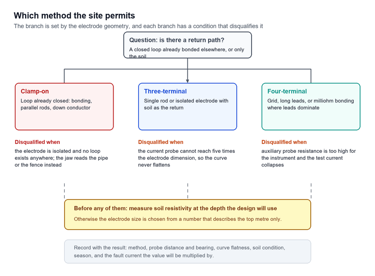
The choice of method follows from the shape of the electrode and from whether a return path exists, and it should be fixed before the instrument’s range, accuracy or data storage is discussed. A single driven rod is a three-terminal job, a grid is a four-terminal job with long leads, a bonding connection is a four-terminal job with a low range, and a set of parallel rods already bonded together is the one case where a clamp saves an hour of driving probes.
A clamp ground resistance tester induces a current into a conductor that is already part of a closed loop and measures the resulting field, so the reading is the impedance of the entire loop rather than the resistance of one electrode. That is a feature when the question is whether a lightning protection down conductor is still connected to the ring, and a trap when the question is what the resistance of a single rod is, because the loop includes the soil path, the parallel rods, the bonding conductors and the supply neutral if it is bonded to earth.
| Situation | Method | Why | Instrument features that matter |
|---|---|---|---|
| Single driven rod, first commissioning | Three-terminal | Only method that isolates the rod | Probe spacing guidance, interference rejection |
| Substation grid, acceptance test | Four-terminal | Long leads, low values, need lead resistance cancelled | 0.001 Ω resolution, current up to 5 A, 45/55 Hz dual frequency |
| Bonding continuity between structures | Four-terminal, low range | Values in milliohms, lead resistance dominates | Low range, 0.001 Ω resolution, test current stability |
| Rows of parallel rods already bonded | Clamp | No return path can be established otherwise | Jaw size, immunity to external magnetic field |
| Lightning protection down conductors | Clamp | Continuity of the loop is the question | Jaw opening for flat tape, memory for a route walk |
| Soil resistivity for design | Four-terminal, Wenner array | Gives resistivity against depth | Spacing range, reading at 1 m to 50 m |
| Tower footing on a transmission line | Clamp plus three-terminal | Clamp for screening, three-terminal for the value | Both functions in one unit |
When the specification sheet is misleading
The headline accuracy figure on most datasheets is quoted against a resistance range and says nothing about the conditions under which it holds. Two extra numbers decide whether it will be met on site: the maximum interference voltage the instrument can tolerate while still resolving the signal, and the maximum resistance of the auxiliary probes at which the instrument will still inject its rated current.
A unit rated at ±2% of reading on the 0–20 Ω range (IEC 61557-5:2007 accuracy classes) that gives up when the potential probe resistance exceeds 50 kΩ is a different instrument from one that holds its accuracy with 100 kΩ probes, and the difference shows up on the first rocky site. Ask for both figures in writing, together with the test current at the low end of the range, because a current that falls to 1 mA in dry sand gives a reading dominated by noise.
Fall of potential: probe spacing and why 61.8 percent
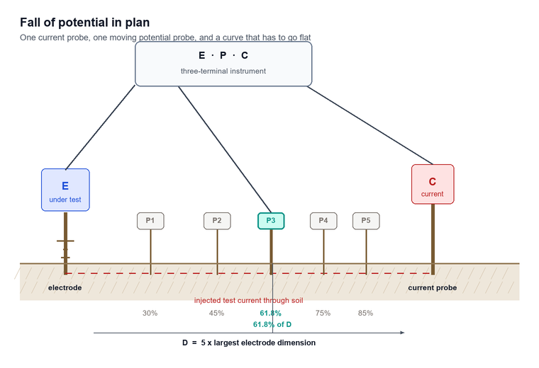
Fall of potential places a current probe far enough from the electrode that the electrode and the probe look like two separate hemispheres in the soil, then measures the potential at a series of intermediate points and takes the value where the potential curve is flattest. For a single hemisphere the flat region falls at 61.8% of the current-probe distance, and that is the number most field guides quote, but the number is a consequence of the geometry rather than a rule to be applied blindly.
The rule that makes the method valid is the distance, not the percentage. The current probe has to be far enough away that its own resistance sphere does not overlap the electrode’s, which in practice means at least five times the largest dimension of the electrode — five times the rod length for a rod, five times the diagonal for a grid. A 3 m rod therefore needs the current probe at 15 m or more, and a 60 m grid needs 300 m, which is why a large substation survey needs a cable reel and a vehicle rather than a hand-held lead.
Reading the curve instead of the point
A single reading at 61.8% is not a fall-of-potential measurement; it is a number that happens to have been taken at a plausible distance. The method requires at least three potential-probe positions, ideally five, plotted against distance, and the result is accepted only if the curve is flat over the outer third and the resistance changes by less than about 5% between adjacent positions (IEEE Std 81-2012).
The field pattern that accounts for most rejected grid tests we see is not a bad instrument but a short cable. On a 60 m by 40 m substation grid the diagonal is 72 m, so the current probe belongs at 360 m; most hand-held lead sets ship with 50 m and 100 m reels, and the crew lays out what the reel allows. The measured value then rises with potential-probe distance instead of flattening, and the number reported is whatever the last step happened to read.
The shape of a non-flat curve diagnoses the error. A curve that rises continuously with distance means the current probe is too close, so the potential probe is still inside the electrode’s own sphere of influence and the reading is too high — move the current probe out and repeat. A curve that falls continuously means the potential probe is picking up a parallel return path, often a metal pipe, a cable sheath or a building foundation, so the true electrode resistance is higher than the reading. A curve with a hump in the middle usually means a buried metallic object between the probes.
The probe spacing table
| Electrode under test | Largest dimension | Minimum current-probe distance | Practical potential-probe steps, for a ground resistance tester (percentage of current-probe distance) |
|---|---|---|---|
| Single rod, 3 m | 3 m | 15 m | 30, 40, 50, 60, 70, 80 |
| Three rods in a triangle, 3 m | 6 m | 30 m | 30, 40, 50, 60, 70, 80 |
| Ring earth of a small building, 20 m across | 20 m | 100 m | 40, 50, 60, 70, 80 |
| Substation grid, 60 m diagonal | 60 m | 300 m | 50, 55, 60, 65, 70, 75 |
| Tower footing | 3 to 8 m | 15 to 40 m | 40, 50, 60, 70, 80 |
The percentages are given as a range and not as 61.8% alone because the potential-probe steps are what produces the curve; the value at 61.8% is then read off the plotted line rather than measured by planting the probe at exactly that fraction of a distance nobody can measure to the centimetre in a field.
Soil resistivity: wenner's four electrodes and what the curve says
Soil resistivity is measured with four electrodes driven in a straight line at equal spacing, current injected through the outer pair and voltage read across the inner pair, which gives a resistivity of 2πaR for a spacing a. The reason to measure it rather than look it up is that resistivity is a property of the soil at a site and it varies by four orders of magnitude between saturated clay and solid granite, and it also varies with depth in a way that decides the design.
The spacing is the depth. Current injected through probes a metres apart spreads through a hemisphere of soil of roughly that radius, so a reading at 1 m samples the top metre and a reading at 30 m samples the top 30 m. Taking readings at a series of spacings and plotting resistivity against spacing produces a curve that shows whether the site is uniform, whether there is a low-resistivity layer at depth that a deep rod could reach, or whether the surface layer is the low-resistivity one and a deep rod would gain nothing.
| Material | Typical resistivity (Ω·m) | Consequence for design |
|---|---|---|
| Sea water | About 2 | Essentially a short circuit; corrosion becomes the design driver |
| Clay, moist | 20 to 60 | One or two rods usually reach the target |
| Sand, dry | 200 to 2000 | Rods alone rarely work; extend or use a grid |
| Gravel | 2000 to 3000 | Grid area and surface layer do the work |
| Solid granite | Up to 25000 | Chemical treatment or a remote earth is the only route |
| Ice | Up to 100000 | Seasonal variation dominates any measurement |
Reading the resistivity curve
A curve that rises steadily with spacing indicates a surface layer of low resistivity over a more resistive body, so a deeper rod gains little and the money is better spent on more surface area. A curve that falls with spacing indicates a low-resistivity layer at depth, and a single deep rod or a deep-driven electrode becomes attractive. A curve that is flat means the soil is roughly uniform to the depth explored, which is the easy case for design and the hardest to improve by going deeper.
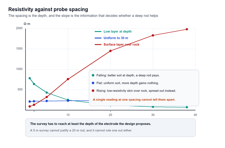
The mistake that costs the most money is reading a resistivity survey at one spacing and treating it as a soil property. A single reading of 80 Ω·m at 2 m spacing has been used to justify 3 m rods across sites where the same instrument reads 900 Ω·m at 20 m, because the top two metres were wet clay and everything below was decomposed rock. The survey has to reach at least the depth of the electrode the design proposes, or the design is being built on the shallowest and wettest part of the profile.
The depth of the measurement matters as much as the values, because the design depth has to be inside the depth explored. A resistivity survey carried out only to 5 m says nothing about whether a 20 m rod would reach better soil, and a design that assumes a low-resistivity layer at 15 m on the basis of a 5 m survey is a design built on a guess.
Standards cited in this section
- IEC 61557-5:2007 governs the instrument and the test current.
- IEEE Std 81-2012 governs the measurement methods, including the Wenner array and the criteria for accepting a fall-of-potential curve.
- IEEE Std 80-2013 governs the resistivity values used in design and the safety criteria the result is judged against.
From measurement to safety limit: what the number has to satisfy
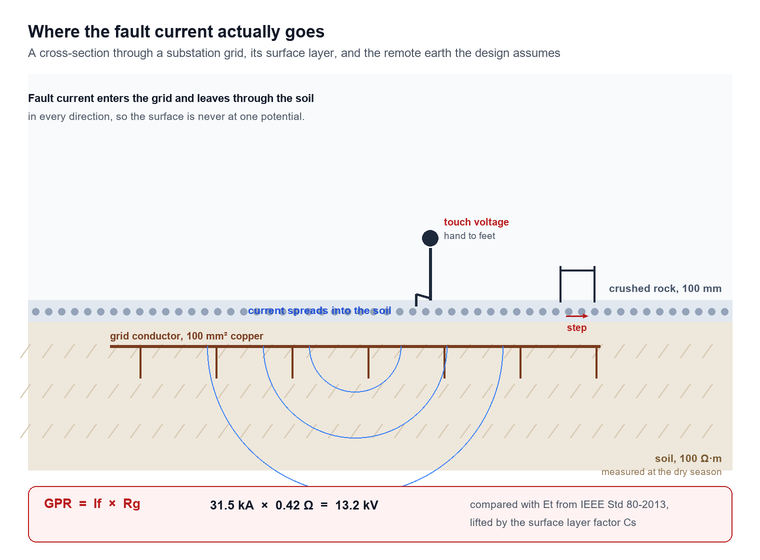
The resistance of an earth electrode on its own satisfies nothing; what the standards constrain is the voltage that appears across a person during a fault and the ground potential rise that appears on the installation. IEEE Std 80-2013 sets the tolerable touch and step voltages from body weight, fault clearing time and the resistivity of the surface layer, and an electrode reading of 1 Ω can fail those limits while one reading of 5 Ω passes them, depending on the fault current and the surface.
For a 50 kg person the tolerable touch voltage is (1000 + 1.5·Cs·ρs)·0.116/√ts volts, and the tolerable step voltage is (1000 + 6·Cs·ρs)·0.116/√ts volts, with ts the fault clearing time in seconds and Cs a derating factor for the surface layer (IEEE Std 80-2013). For a 70 kg person the constant 0.116 becomes 0.157, which raises the limit by about a third. The surface layer matters more than most people expect: a 100 mm layer of crushed rock at 3000 Ω·m over soil at 100 Ω·m gives a derating factor of roughly 0.78, and that single term can lift the tolerable touch voltage by several hundred volts.
| Quantity | Symbol | Expression (50 kg) | What it depends on |
|---|---|---|---|
| Tolerable touch voltage | Et | (1000 + 1.5·Cs·ρs)·0.116/√ts | Surface resistivity, fault clearing time |
| Tolerable step voltage | Es | (1000 + 6·Cs·ρs)·0.116/√ts | Surface resistivity, fault clearing time, step span |
| Surface layer derating | Cs | 1 − 0.09(1 − ρ/ρs)/(2hs + 0.09) | Layer thickness, layer resistivity, soil resistivity |
| Ground potential rise | GPR | If · Rg | Fault current into earth, grid resistance |
The design sequence that follows is: measure the soil, choose the electrode geometry, measure the installed resistance, multiply by the fault current that the earth will actually carry, and compare the product with the tolerable touch voltage modified by the surface layer. A specification that stops at “below 1 Ω” or “below 5 Ω” skips the multiplication and the comparison, which are the two steps that decide whether the installation is safe.
Why the reading is not the same as the design value
The measured resistance of a grid and the resistance used in the design calculation differ for three reasons, and all three make the measured value look better than the design assumes. The measurement uses a small test current, so it sees the soil as it is at that moment rather than at the temperature and moisture of a fault; it usually samples a path that includes the surface layer, which is the lowest-resistivity part of the soil in wet weather; and it is taken at one season, while the design has to hold at the worst season.
IEEE Std 81-2012 recommends recording the soil temperature and moisture at the time of the test and repeating the survey in the dry season, which is the practical way to bound the seasonal variation. A grid measured at 0.4 Ω in spring can read 1.2 Ω in a dry autumn on a site with a shallow clay layer, and the design value has to be the higher figure.
A commissioning record that survives a review usually carries four lines the template leaves out: the depth of the electrode as actually installed rather than as drawn, the distance and bearing of the current probe, the number of potential-probe positions plotted, and the weather over the preceding fortnight. When two surveys disagree, those four lines almost always explain it, and without them the disagreement costs a second mobilisation.
Wiring, probe placement and the errors that survive a correct reading
A correct reading depends on the probes being where the drawing says they are, the leads being laid in the right direction and the clips making contact with bare metal rather than paint, and each of those three conditions fails silently. The instrument cannot tell an operator that the potential probe was driven into a buried cable duct, so the verification is procedural and has to be built into the test.
The single most common error is laying the potential lead parallel to and close to the current lead. The current in the current lead produces a voltage along its length, and a potential lead running beside it picks up a fraction of that voltage by mutual coupling, which adds to the reading. The fix is simple and is almost always skipped: lay the two leads in opposite directions, or separate them by several metres, and never coil the surplus lead on the ground beside the current lead.
A verification routine that costs five minutes
- Measure the resistance of the leads alone, shorted at the far end, and record it. On a long run this is the figure that will be subtracted later, and on a bad lead it is the figure that reveals the fault.
- Drive the current probe at the calculated distance, in a direction away from buried services, and check its own resistance with the instrument’s probe-resistance function if it has one.
- Take readings at five potential-probe positions and plot them, rather than accepting the value at one position.
- Reverse the current and potential leads and repeat one reading; a genuine electrode gives the same value, a reading contaminated by a direct voltage does not.
- Record the soil condition, the recent weather, the probe depths and the line directions on the same sheet as the numbers.
What each symptom points at
| Symptom | Likely cause | Check before changing the instrument |
|---|---|---|
| Reading falls as the potential probe moves outward | A parallel return path, such as a pipe, a cable sheath or a foundation | Move the probe line 90 degrees and repeat |
| Reading rises without flattening | Current probe too close, or the current lead clipped short | Extend the current probe to five times the diagonal |
| Reading differs when the current and potential leads are swapped | A direct voltage on the electrode, from cathodic protection or traction | Use a frequency-selective setting or a different test frequency |
| Reading drifts over minutes | Stray current from a nearby load, or a drying probe | Rewet the probes, repeat, note the time of day |
| Reading is stable but far higher than the design | Poor probe contact in dry surface material | Increase probe depth, add water, check the probe resistance limit |
| Two instruments disagree by a factor of two | One is reading a loop, the other an electrode | Confirm which method each was set to before comparing |
When the reading cannot be trusted
A reading that changes when a nearby machine starts, that differs between two instruments on the same electrode, or that drifts over a few minutes is telling you about the site rather than about the instrument. Stray current from a railway traction system, a cathodic protection system or a large drive can all put a voltage on the electrode that the instrument has to reject, and a frequency-selective instrument with a stated interference tolerance is the answer.
Clamp measurement: bonding continuity and parallel rods
A clamp instrument is the fastest way to answer a continuity question and the only practical way to test an electrode that cannot be isolated, and it is also the instrument most often used for a question it cannot answer. The principle is a transformer: one winding induces a current at a defined frequency into the loop formed by the conductor in the jaw, and a second winding measures the current that flows, so the reading is the impedance of that loop at the test frequency.
The loop always contains more than the electrode. For a lightning protection down conductor bonded to a ring earth, the loop is the down conductor, the ring, the soil between the ring and any other grounded point, and whatever else is bonded in between. For a row of twenty rods on a substation perimeter, the loop for any one rod includes the other nineteen in parallel, so the reading is the parallel combination and tells you the rods are connected rather than what any single rod measures.
| Question | Clamp reading tells you | Clamp reading misleads you about |
|---|---|---|
| Is this down conductor still bonded? | Yes, a finite low value means the loop is closed | Nothing, provided the loop is genuinely closed elsewhere |
| What is the resistance of this single rod? | Nothing directly | Everything; the reading is the parallel combination |
| Are all the rods on this perimeter connected? | Yes, an unexpectedly high value flags a break | The value of any individual rod |
| Is this tower footing adequate? | A screening indication | The isolated footing resistance without a second method |
| Is the equipotential bonding intact? | Yes, at the resolution of the jaw | Contact resistance at the clamp faces if they are dirty |
Jaw size, frequency and the interference limit
Three specifications decide whether a clamp will work on a given installation. The jaw opening has to accept the conductor, which for a flat lightning tape is a different requirement from a round cable, and 68 mm is a typical figure for a general-purpose unit. The test frequency has to be high enough that the loop impedance is dominated by resistance rather than by the inductance of a long loop, which is why clamp instruments work at frequencies well above the supply. And the immunity to external fields and to the voltage on the conductor has to exceed what the site presents; a stated tolerance of 40 A/m of external magnetic field and 1 V/m of external electric field is a reasonable working figure, and a substation can exceed both.
The limitation that no specification fixes is the one that matters most: a clamp cannot see a rod that is not part of a loop. Drive a single rod in an open field, clamp it, and the instrument will either refuse to read or return a value that reflects the capacitive and soil path back to the instrument’s own reference, neither of which is the electrode resistance.
Frequency-selective instruments and interference rejection
An earth electrode in a live substation is not a passive object, and that is the whole problem. It carries current from the supply system through the soil, it sits at a voltage relative to a remote earth, and that voltage is at the power frequency with harmonics riding on top. A frequency-selective instrument measures at frequencies chosen to avoid that interference and rejects the rest, and the specification describing how much interference it can survive decides whether it works at your site rather than at a test bench.
An earth ground tester with frequency selection typically offers four test frequencies in the region of 90 to 130 Hz and an automatic mode that measures the interference first and picks the quietest frequency. The choice of this band is not arbitrary: it is high enough to be clear of the power frequency and its lower harmonics, and low enough that the soil behaves resistively rather than capacitively, which is the condition the resistivity formula assumes.
The interference tolerance is quoted as a voltage, and the figure to compare is the voltage that will actually be present. A substation with a solidly earthed neutral and a few amps of unbalanced load current can put several volts between the electrode under test and a remote probe; an instrument rated to tolerate 50 V of 50 Hz interference will still measure under those conditions, while one rated at 5 V will not. For a transmission substation, this single number is worth more than a decimal place of accuracy.
| Feature | Why it is specified | What to ask for |
|---|---|---|
| Multiple test frequencies | Avoids interference at the site | The list of frequencies, not just “frequency selective” |
| Automatic frequency selection | Picks the quietest band without an engineer’s judgement | The time it takes and whether it repeats during the test |
| Interference voltage tolerance | Decides whether the site is testable at all | A figure in volts at 50 Hz |
| Test current at low resistance | Keeps the signal above the noise floor | The current at the bottom of the range |
| Probe resistance limit | Decides whether dry or rocky ground can be tested | Maximum auxiliary probe resistance |
Instrument classes in practice: handheld, clamp and grid systems
Three product families cover almost every requirement, and they differ in the size of the electrode they can test and in how much current they can inject rather than in whether they are accurate. A handheld four-terminal unit is the general-purpose instrument, a clamp unit is the continuity tool, and a grid system is the instrument that injects amps instead of milliamps, survives a day of cable laying and is loaded into a vehicle rather than a tool bag.
| Family | Typical range | Test current | Weight | Best for |
|---|---|---|---|---|
| Handheld four-terminal | 0.00 Ω to 30 kΩ, resistivity to 9000 kΩ·m | Above 20 mA, open-circuit up to 40 V | Around 1.3 kg | Distribution rods, small grids, resistivity surveys |
| Handheld three-terminal with voltage input | 0.00 Ω to 20 kΩ, plus AC and DC voltage | Similar order | Around 1.9 kg | Commissioning where a voltage check is also needed |
| Clamp-on | 0.01 Ω resolution | Induced, no probes | Around 1 kg | Bonding continuity, parallel rods, down conductors |
| Grid system | 0.030 Ω to 2000 Ω | 1 A to 5 A in steps, output to 400 V | 27 kg main unit | Substation grids where interference is high |
The grid system earns its weight in two situations. The first is a large grid, where the resistance to be measured is a few tenths of an ohm and the interference is tens of volts: a milliamp test current cannot resolve a signal that small against that much noise, so the instrument has to inject amps. The second is a grid where the current probe must be 300 m away and the loop resistance of the leads alone is several ohms, which a four-terminal arrangement cancels but a small instrument cannot drive.
Matching the instrument to the site
For a plant with twenty distribution boards and a ring earth, a handheld four-terminal unit and a clamp cover everything. For a 132 kV substation with a grid of 80 m by 60 m and a fault current of 31.5 kA, the grid system is not optional: the measurement has to be made at 45 and 55 Hz with several amps, because the 50 Hz interference on that grid will exceed what a small instrument can reject, and the resistance is low enough that the resolution matters.
What each specification is actually deciding
| Specification | What it decides on site | Typical figure worth asking for |
|---|---|---|
| Resistance range | Whether the instrument can read the electrode or only the soil | Bottom of range at 0.001 Ω for grids, 0.01 Ω for rods |
| Test current | Whether the signal survives the interference | Above 20 mA at the low end for handheld, 1 A to 5 A for a grid system |
| Open-circuit output voltage | Whether current can be driven through a long, dry soil path | Around 40 V handheld, up to 400 V for a grid system |
| Interference tolerance | Whether a live substation can be tested at all | A stated figure in volts at 50 Hz, not just “high immunity” |
| Auxiliary probe resistance limit | Whether rocky or dry ground can be tested | 50 kΩ is workable, 100 kΩ is better |
| Memory and export | Whether the curve can be plotted after the fact | At least 100 records, USB or Bluetooth export |
Limitations and boundaries
The numbers from an earth test carry less certainty than their decimal places suggest, and five limitations bound what they can support, from the soil around the electrode to the acceptance criterion the result is compared against.
The first is that the instrument cannot separate the electrode from its surroundings. A three-terminal reading includes the resistance of the soil within the electrode’s sphere of influence, which changes with moisture and temperature, and a clamp reading includes every parallel path in the loop, so neither is a property of the metal alone. Anyone comparing two surveys has to compare the conditions as well as the numbers.
The second is that the measurement is taken at a current far below the fault current. Soil behaves non-linearly at high current density because of heating and ionisation around the electrode, and the resistance at a 31.5 kA fault is not the resistance measured at 20 mA. The difference is usually in the conservative direction for a well-designed electrode, but it means the measured value cannot be used to predict behaviour at fault current without engineering judgement.
The third is that a clamp cannot test an isolated electrode at all, and no amount of instrument quality changes that. If a rod has no return path, the correct answer is to drive probes and use a three- or four-terminal method, and an operator who reports a clamp reading on an isolated rod has reported a number with no defined meaning.
The fourth is cost and logistics against benefit. A grid system costs several times a handheld unit, needs two people, a vehicle and most of a day, and produces one number. For a distribution network of two hundred small earthing points, the handheld unit and a clamp will cover the whole network in the time the grid system takes to test one substation, and the marginal accuracy of the grid system buys nothing at those sites.
The fifth is that the acceptance criterion is often written as a single ohm value in a specification that predates the safety analysis. A 1 Ω limit applied to a grid carrying 40 kA gives a ground potential rise of 40 kV, which no surface layer makes tolerable, while the same 1 Ω on a 2 kA installation is generous. The measurement is only as useful as the criterion it is compared against, and correcting the criterion is often worth more than improving the instrument.
Frequently asked questions
These are the questions that come up most often when a ground resistance tester is being specified or when a commissioning test has produced a number nobody believes. Each answer stands on its own.
Can I use a clamp meter instead of driving probes?
Only where the electrode is part of a closed loop with a return path. A clamp works on bonding continuity, on parallel rod arrays and on lightning protection down conductors, and it reads the impedance of the whole loop rather than one electrode. For an isolated rod it has no return path and the reading is undefined, so a three- or four-terminal test with auxiliary probes is the only valid method.
Why does the reading change between two visits?
Soil moisture and temperature are the usual causes, and the variation is largest where the electrode’s resistance is dominated by a shallow surface layer. A grid reading 0.4 Ω in wet spring can read over 1 Ω in a dry autumn. Record the weather, the soil condition and the depth of the electrode on the report, and repeat the survey in the driest season to bound the range.
How far apart do the probes have to be?
The current probe goes at least five times the largest dimension of the electrode from it: 15 m for a 3 m rod, 100 m for a 20 m ring, 300 m for a 60 m grid. The potential probe is moved in steps between about 30% and three-quarters of that distance (IEEE Std 81-2012 probe-step practice), and the value is read from the flat part of the curve, which for a single hemisphere falls near 61.8% (IEEE Std 81-2012; the 5% flatness check between adjacent positions comes from the same clause set).
What is an earth ground resistance tester with frequency selection for?
It measures at frequencies between 15 Hz and 2 kHz, typically around 90 to 130 Hz, to sit clear of the power frequency and its harmonics, then demodulates its own signal out of the interference. At a live substation, several volts of 50 Hz can appear across the electrode, and a frequency-selective instrument with a stated interference tolerance still measures while a direct-reading instrument cannot.
Does a lower resistance mean a safer installation?
Not on its own. Safety depends on the ground potential rise, which is the fault current into earth multiplied by the grid resistance, compared against tolerable touch and step voltages from IEEE Std 80-2013. A 1 Ω grid carrying 40 kA produces 40 kV, which no surface layer makes safe, while 5 Ω at 2 kA is comfortable. The resistance has to be multiplied before it means anything.
How do I measure soil resistivity and how deep does it reach?
Drive four electrodes in a straight line at equal spacing a, inject current through the outer pair, read voltage across the inner pair, and calculate resistivity as 2πaR. The spacing is roughly the depth sampled, so readings at 1 m, 2 m, 5 m, 10 m and 30 m describe the top 30 m. Plot resistivity against spacing to see whether a deep rod would reach better soil.
What causes a negative or wildly fluctuating reading?
A direct voltage on the electrode, from a cathodic protection system, a traction return or a large drive, will offset the measurement, and reversing the leads is the quickest check; a genuine electrode reads the same either way. Wild fluctuation usually means the potential probe is in dry surface material with poor contact, or that the potential lead is running beside the current lead and picking up its voltage.
Conclusion
The specification of an earth test instrument reduces to four decisions in a fixed order: which method the geometry of the electrode permits, how far the probes have to be and therefore how much cable the job needs, how much interference the site presents and therefore how much test current and frequency selection the unit must have, and what safety criterion the result will be compared against. Models are chosen last, and a specification written in that order usually narrows the market to a handful before any ground resistance tester catalogue is opened.
For a buyer, the practical sequence is to list the electrodes to be tested with their dimensions, the fault current at each, the surface layer and the season the test will run in, and only then to ask for ranges, test currents, interference tolerances and probe-resistance limits. That list also settles whether one instrument or two are needed: a handheld four-terminal unit plus a clamp covers a distribution network, while a substation grid needs the heavy system as well, and a unit bought for the second job alone will sit unused for the rest of the year.
Baoding Houfeng supplies handheld units, clamp instruments and the grid systems used for substation acceptance work. The instruments sit under the grounding system tester category page, with individual units on the four-terminal earth tester, the three-terminal earth resistance tester, the clamp-on unit and the ground grid resistance testing system pages, and the equipotential bonding tester covers the milliohm side of the same work. For sites where the earthing question arrives together with an insulation question, the insulation resistance test guide covers the megohmmeter side, and the cable testing and monitoring guide covers the sheath and continuity tests that share the same leads and the same afternoon. Company background is on the about us page. For a project that mixes a distribution network with one substation grid, contact us with the electrode dimensions, the fault current and the soil description, and we will tell you which combination covers both.
References and technical sources
- IEC 61557-5:2007, Electrical safety in low voltage distribution systems up to 1000 V a.c. and 1500 V d.c. — Equipment for testing, measuring or monitoring of protective measures — Part 5: Resistance to earth, International Electrotechnical Commission, 2007, which defines the 15 Hz to 2 kHz test current band and the measurement methods for earth electrode resistance testers. webstore.iec.ch
- IEEE Std 81-2012, IEEE Guide for Measuring Earth Resistivity, Ground Impedance, and Earth Surface Potentials of a Grounding System, IEEE Standards Association, 2012, which defines the fall-of-potential method, the Wenner array and the criteria for accepting a measured curve. standards.ieee.org
- IEEE Std 80-2013, IEEE Guide for Safety in AC Substation Grounding, IEEE Standards Association, 2013, which gives the tolerable touch and step voltage expressions, the surface layer derating factor and typical soil resistivity values used in this guide. standards.ieee.org
- IEEE Std 142-2007, IEEE Recommended Practice for Grounding of Industrial and Commercial Power Systems, IEEE Standards Association, 2007, which covers the design of grounding systems for industrial installations and the treatment of parallel electrodes. standards.ieee.org
- NETA, A Guide to Understanding IEEE Standard 80 and Its Application to Grounding System Testing, InterNational Electrical Testing Association, which sets out how measured grid resistance is compared against the tolerable voltage criteria in field practice. netaworld.org
- International Electrotechnical Commission, IEC 60364-5-54:2011, Low-voltage electrical installations — Part 5-54: Selection and erection of electrical equipment — Earthing arrangements and protective conductors, which sets the earthing and bonding requirements that the continuity tests verify. webstore.iec.ch
- U.S. Department of Energy, Electrical Safety Handbook, which summarises the application of ground potential rise and touch voltage limits at industrial facilities. energy.gov