Leave your message

-
Leon Zhang sales consultant
-
Email: zxl635973785@gmail.com
-
Phone/WhatsApp/Wechat: +86 13655813266

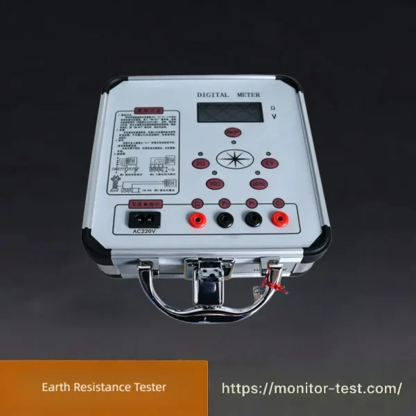
HF-GT-210 Earth Resistance Tester
This portable Earth Resistance Tester measures grounding, loop resistance, AC voltage and current. It features a color LCD, data storage, alarm reminder and strong anti-interference performance, widely used for grounding detection in power, communication and industrial fields.
Send your requirements, we will quote for you within 12 hours
The earth resistance tester is a classic digital measuring instrument for grounding system inspection. Adopting the four-wire measurement principle, it precisely tests grounding resistance and ground voltage with multiple adjustable measuring ranges. Sturdy portable metal casing ensures durability onsite. Widely applied in power stations, communication stations, factories and lightning protection projects to verify earthing safety and comply with electrical safety codes.
Product Features
- The device features a high-strength aluminum alloy housing. Its circuit applies phase-locked loop synchronous detection together with switched capacitor filters to suppress power frequency and radio frequency interference, delivering outstanding anti-interference performance.
- It adopts DC/AC conversion technology to convert direct current into stable low-frequency alternating current for accurate measurement.
- Variations of auxiliary earth resistance within 0~2kΩ (RC) and 0~40kΩ (RP) will not interfere with final measurement results.
- No manual balancing adjustment is required. Equipped with a 3½-digit LCD display, it can measure earth resistance, conductor low resistance, soil resistivity and AC earth voltage.
- When the test loop is disconnected, the digit “1” will be displayed to indicate overrange, consistent with universal measuring instrument conventions.
Technical Specifications
| Category | Item | Parameters |
|---|---|---|
| Operating Conditions | Ambient Temperature | 0℃ ~ +45℃ |
| Relative Humidity | ≤ 85% RH | |
| Measuring Range & Constant Current (RMS Value) | Resistance | 0~2Ω (10mA), 2~20Ω (10mA), 20~200Ω (1mA) |
| Voltage | AC 0 ~ 19.99V | |
| Measurement Accuracy & Resolution | Accuracy | 0~0.2Ω: ±3% ±1 digit 0.2Ω~199.9Ω: ±1.5% ±1 digit 1~19.99V: ±3% ±1 digit |
| Resolution | 0.001Ω, 0.01Ω, 0.1Ω, 0.01V | |
| Measuring Error Caused by Auxiliary Earth Resistance & Voltage | Allowable Auxiliary Earth Resistance RC (Between C1 & C2) | < 1.8kΩ |
| RP (Between P1 & P2) | < 40kΩ, error ≤ ±5% | |
| Allowable Earth Voltage | ≤ 5V (Power frequency RMS), error ≤ ±5% | |
| Power Supply & Power Consumption | Maximum Power Dissipation | ≤ 2W |
| Power Source | 6.8V~9V (6 pcs No.5 Ni-MH rechargeable batteries), or external AC 220V power supply | |
| Overall Dimensions | 220mm × 200mm × 105mm | |
| Weight | ≤ 1.4kg |
Earth Resistance Tester
- Measure grounding resistance of power substations, transmission towers, distribution cabinets and electrical equipment to ensure safe grounding performance.
- Test ground grid resistance for buildings, factories and photovoltaic power stations, preventing electric leakage and lightning strike hazards.
- Verify earthing system compliance with international electrical safety standards before equipment commissioning, regular maintenance and acceptance inspection.
- Detect poor grounding, broken grounding wires and corrosion defects of buried grounding electrodes effectively.
FAQ
Q: What is an Earth Resistance Tester used for?
A: It is a professional electrical measuring instrument applied to measure the resistance of grounding electrodes, grounding grids and overall earthing systems. It checks whether leakage and fault current can be safely released into the earth, protecting staff and electrical equipment from electric shock, lightning strikes and short-circuit hazards. It can also test soil resistivity to assist the design of new grounding projects.
Q: What measuring methods are supported by a digital Earth Resistance Tester?
A: Three common measuring methods are available. The 2-pole method is adopted for simple grounding continuity inspection with ordinary precision. The 3-pole fall-of-potential method is widely used for conventional grounding resistance measurement. The 4-pole Wenner method features high accuracy and is specially used for soil resistivity detection in grounding system design.
Q: What are the qualified earth resistance values for different application scenarios?
A: Test results shall comply with IEC, IEEE and NEC international standards. The qualified value for residential buildings is no more than 25Ω; general factories and commercial buildings require resistance below 10Ω; substations, power plants and computer rooms need grounding resistance ≤5Ω; lightning protection grounding for communication towers is generally controlled within 10Ω, which can be adjusted according to actual project demands.
Q: How often should we conduct regular earth resistance testing?
A: Ordinary industrial and civil buildings need testing every 6 to 12 months. Substations, high-voltage stations and communication base stations require quarterly inspection. Extra testing must be carried out right after thunderstorms, soil changes, grounding grid reconstruction and equipment maintenance.
Q: Why do the measured readings keep fluctuating unstably?
A: Unstable data is mainly caused by poor contact between ground probes and soil, strong electromagnetic interference from surrounding transformers and high-voltage cables, inconsistent soil humidity and temperature, as well as loose connections of test cables. You can firmly insert probes into soil, slightly water dry soil, stay away from high-power electrical facilities and tighten all wire terminals to solve this problem.
Q: Does soil humidity exert great influence on earth resistance test results?
A: Yes. Higher soil moisture improves soil conductivity and lowers grounding resistance, while dry soil will obviously increase resistance values. It is recommended to record weather conditions during each test for accurate comparison of periodic detection data.
Q: Do I need to disconnect all connected equipment from the grounding bar before measurement?
A: Yes, disconnection is highly recommended. Connected electrical equipment will cause stray current interference leading to inaccurate data. Besides, reverse current generated during testing may damage internal circuits of both the tester and on-site power equipment.
Q: What should I do if the tester fails to power on or automatically shuts down during measurement?
A: Insufficient battery power is the most common reason, you need to replace dry batteries or fully charge lithium batteries. If the battery metal contacts are oxidized and rusted, clean the shrapnel contacts. If the problem still exists, the internal power supply circuit is faulty and professional after-sales repair is required.
Q: What does OL/overload display on the screen mean?
A: The overload prompt appears when test cables are broken or improperly connected, ground probes are not inserted deep enough into the earth, or the grounding electrode itself has abnormal ultra-high resistance. Please check wiring and probe installation status first, then inspect the integrity of the on-site grounding system.
Q: Why are test results inconsistent with data measured by other instruments?
A: The instrument may pass its valid calibration period; the spacing between ground stakes fails to meet standard requirements; stray ambient current also affects measurement precision. It is suggested to calibrate the tester once a year, follow standard probe layout rules and avoid strong electromagnetic interference areas during testing.
Q: How frequently does an Earth Resistance Tester need official calibration?
A: Annual compulsory calibration is required for power industry, industrial enterprises and metrology departments. Calibration with standard resistance blocks can ensure the measuring precision meets international electrical test specifications.
Q: What daily maintenance and storage precautions should be followed?
A: Clean mud, dust and moisture on the device and test leads after each use. Take out batteries for long-term storage to prevent liquid leakage from corroding internal components. Keep the instrument in a cool and dry place, avoid heavy collision, rain and high-temperature environment. Do not pull test cables forcibly to prevent internal wire breakage.
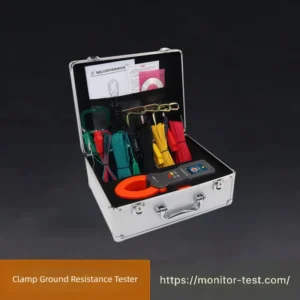
Q: What is the difference between clamp-on Earth Resistance Tester and stake-type Earth Resistance Tester?
A: Stake-type testers adopt 3-pole or 4-pole measurement with high accuracy, applicable to all grounding occasions but need manual embedding of ground probes. Clamp-on testers require no ground stakes, support rapid measurement for multi-loop parallel grounding systems, while its precision is slightly lower for single grounding electrode detection.
Q: Is it allowed to operate the Earth Resistance Tester outdoors on rainy days?
A: Outdoor testing in rainy weather is not recommended. Rainwater may permeate into the instrument interior and cause short circuit damage; meanwhile, rain will change soil conductivity and lead to inaccurate and incomparable test data.

Reviews
There are no reviews yet.