

Author: Baoding Houfeng Trading Co., Ltd. — Power Monitoring and Testing Equipment Team,
supplying relay test sets and high voltage test instruments to utilities and EPC contractors since 2026
Technical review: reviewed by the in-house power testing engineering team against IEC 60255-1:2022 and GB/T 7261-2016 practice
Last updated: 18 October 2026
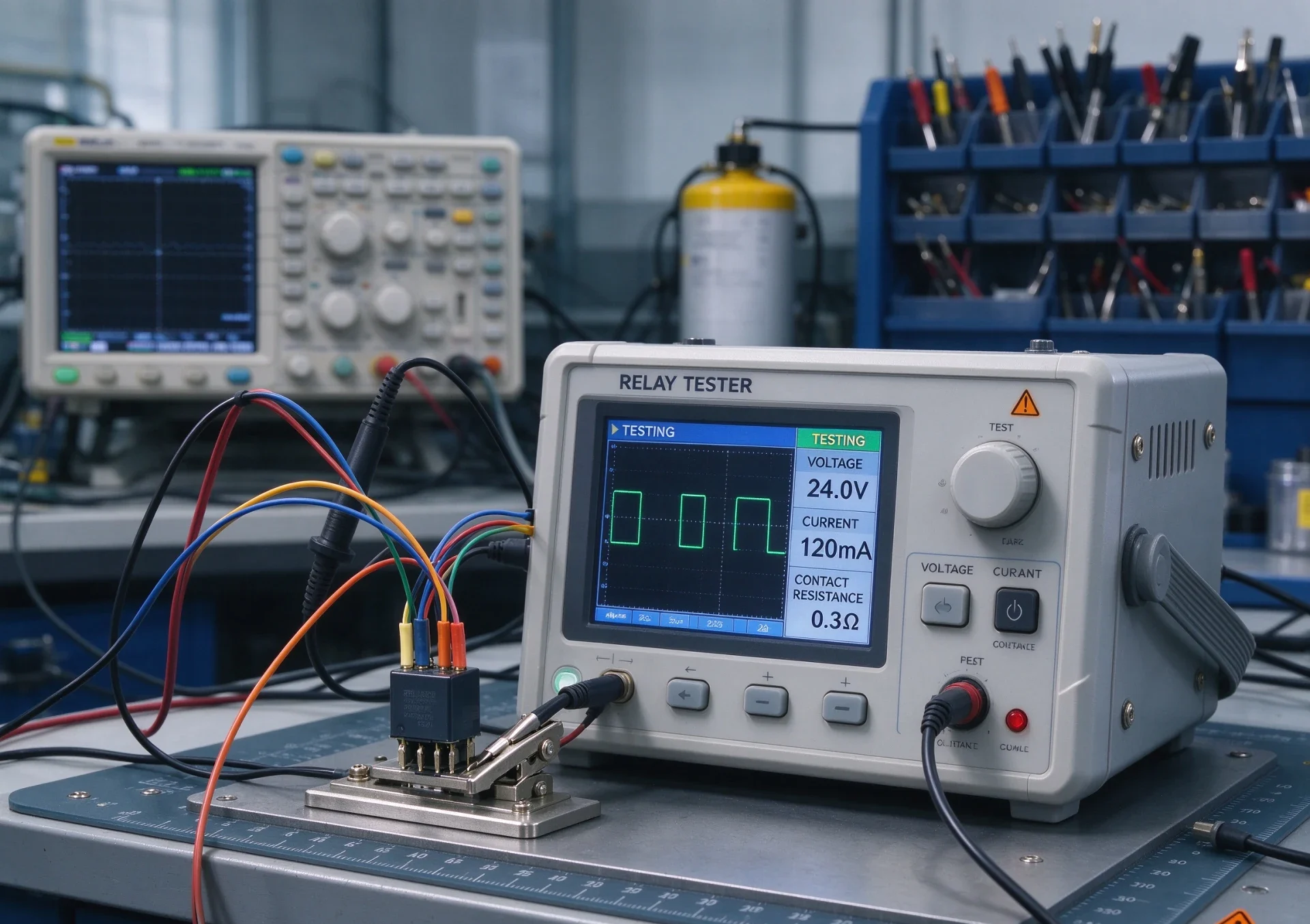
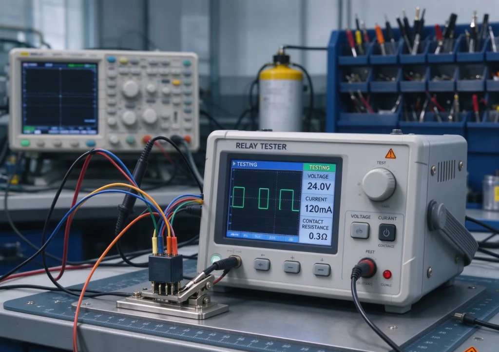
A relay tester is a secondary injection instrument that feeds calibrated voltage and current into a protection relay to prove it picks up, times out and trips at the settings written on its test sheet. Choosing one is a question of source count, timing accuracy and how much of the acceptance record the set can produce on its own, not of catalogue headline numbers or the number of channels printed on the front panel.
Most relay testing problems are not equipment faults. They are mismatches between what the test set can output and what the relay needs to see: a four-channel set asked to run a transformer differential characteristic, a set with no independent auxiliary supply energising the relay under test, or a timing accuracy that cannot resolve a 50 ms breaker failure stage. This guide sets out the specifications that actually decide those outcomes.
Key takeaways
- Relay testing is secondary injection: the relay sees scaled-down currents and voltages that represent a primary fault, and the tester controls what that fault looks like.
- Channel count is the first filter, not the quality mark. Three currents and three voltages cover most feeder and motor protection; transformer differential and busbar schemes usually need six.
- Timing accuracy matters more than output power for most acceptance work, because the pass criterion is usually a settable time band written in the client’s test sheet.
- A tester without an independent auxiliary DC supply forces you to power the relay from a separate source, which doubles the wiring and the ways the test can go wrong.
- Automatic test sequences are only worth the premium if the same relay type appears repeatedly in your workload.
- The record is half the deliverable. A test set that cannot export timestamped results leaves the commissioning engineer rebuilding tables by hand.
What does a relay tester actually do?
The instrument is a controllable source of voltage and current that replaces the real instrument transformers during a test, so the relay under test sees a scaled copy of a primary fault condition. The relay cannot tell the difference between 1 A from a current transformer on a feeder and 1 A from a test set on a bench, which is exactly why secondary injection works as a commissioning and maintenance method.
The instrument does four things. It generates the analogue quantities — typically three to six current channels and three to six voltage channels, each independently programmable in amplitude, phase angle and frequency. It sequences those quantities over time, so the relay sees a prefault condition, then a fault, then a trip. It measures the relay’s response: the current at which an overcurrent element operates, the time from fault inception to contact closure, the phase angle at which a directional element changes decision. Finally it records the result against the setting it was testing.
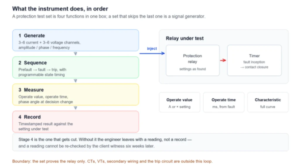
That last point is where cheap sets fail in practice. A tester that can produce a fault but cannot timestamp the response leaves the engineer with a stopwatch and a judgement call, and neither survives an audit by the client’s commissioning witness. The measurable output — operate value, operate time, characteristic curve — is what the test report is built from.
Fuse and relay tester: one name, three different instruments
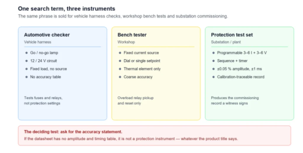
The phrase is used for at least three unrelated product families, and buying the wrong one is a common and expensive mistake that only becomes visible when the first commissioning witness asks for an accuracy statement the instrument cannot provide. An automotive version of the tool checks blade fuses and 12 V or 24 V relays in a vehicle harness, usually with a simple go/no-go indication and no calibrated source at all.
A substation relay test set is a different class of instrument. It produces programmable AC and DC quantities with specified accuracy, drives the relay through a sequence, and records timing to a resolution measured in milliseconds. Between the two sit bench devices that test thermal overload relays and small electromechanical elements with a fixed current source and a dial.
The distinction that matters for procurement is the accuracy statement. A vehicle tester will say it tests fuses up to 30 A. A protection test set will state something like ±0.05% of setting for amplitude and ±1 ms for timing, because those are the figures a protection engineer has to defend against a commissioning tolerance (accuracy classes and reference conditions in IEC 60255-1:2022). If a datasheet has no accuracy table, it is not a protection instrument regardless of what the product title says.
Protective relay testing: the four test types that matter
Protective relay testing covers four distinct activities, and the set is chosen by which of them dominate your workload rather than by a single overall capability score printed on a comparison sheet. The distinctions follow the structure of IEC 60255-1:2022. That standard sets out the common requirements and test reference conditions for measuring relays and protection equipment (IEC 60255-1:2022, common requirements).
Steady-state testing applies a fixed quantity and raises it slowly until the element operates, giving the pickup value and the reset ratio. Dynamic testing applies a step change and measures the time to operate, which is what most time-graded overcurrent schemes are commissioned on. Characteristic testing traces the whole operating curve by repeating dynamic tests at several current multiples, and it is the only way to prove an inverse-time curve matches its setting. Transient and scheme testing replays a recorded fault or a synthesised sequence across several relays at once, checking the logic between them rather than any single element.
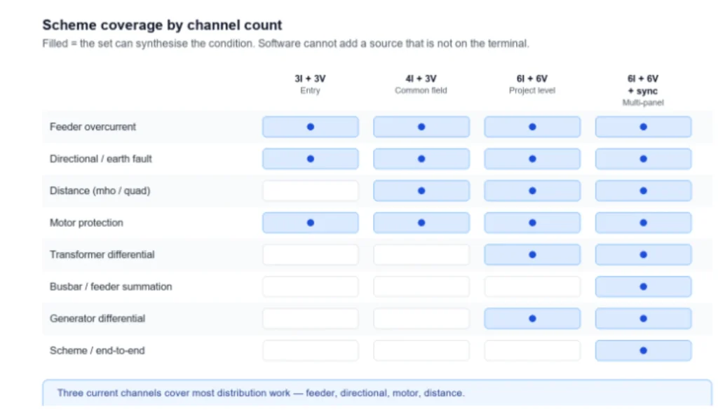
The fourth type is where channel count starts to bind. A transformer differential scheme needs currents from both sides simultaneously, plus a voltage reference for restraint; a busbar protection scheme needs one current per feeder. Sets with three current channels cannot generate those conditions no matter how the software is configured, and retrofitting a second synchronised unit is rarely cheaper than having bought six channels at the start.
Automatic relay testing: when the premium pays back
An automatic set runs a stored test plan against a relay type, presents the operator with pass or fail per element, and writes the results to a report without manual transcription, which is why the argument for buying one always comes back to how repetitive your test workload actually is. The premium over a manually operated set is real, and whether it pays back depends almost entirely on one number: how many relays of the same type you test per year.
The payback case is strongest in three situations. Utilities and service companies that commission the same feeder protection model across dozens of substations get the most value, because the plan is written once and reused. Testing teams under a fixed-price contract benefit because reduced test time per relay directly improves margin. Organisations with a quality system that requires traceable, consistent records benefit because the plan removes operator variation from the result.
The case is weak when your workload is diverse. Writing and validating a test plan for a relay type takes engineering time, and if you see that model twice a year the plan costs more than it saves. Manual operation with good instrument accuracy is the correct choice there, and it is not a compromise. [] The most common regret I have seen in this selection is a buyer who paid for automatic software, then discovered that half of their installed base was older electromechanical relays with no digital interface to sequence against, so the automatic capability sat unused while operators kept running manual tests.
Automatic capability also does not remove the need for engineering judgement. The plan tests what the plan was written to test. If the commissioning engineer misreads the protection philosophy, the automatic set will confirm the wrong settings faster and with a cleaner-looking report.
Key specifications to compare on the datasheet
The datasheet comparison should be built around six specifications that decide whether a set can do the job, because everything else on the page is convenience rather than capability. Other features matter for convenience, but these six decide capability, and they need to be read together rather than ranked.
Output channels are stated as current phases times voltage phases. Three current and three voltage channels cover feeder overcurrent, directional, distance and motor protection. Six current channels are needed where differential or busbar schemes are in scope.
Output range and duration decide what the set can sustain. A channel rated 30 A continuously is very different from one rated 30 A for ten seconds, and a differential test that soaks a restraint winding for several minutes will expose the difference. Confirm both the continuous rating and the duty cycle.
Accuracy is normally quoted as a percentage of setting plus a floor, and the floor dominates at low values. A set quoted at ±0.1% of setting with a 1 mA floor is precise at 5 A and coarse at 20 mA; check where your actual test points sit relative to that floor (reference conditions, IEC 60255-1:2022).
Timing resolution and accuracy decide whether the set can resolve the stages you test. A 1 ms resolution with ±1 ms accuracy is adequate for most overcurrent grading; sub-cycle distance and differential tests need better.
Auxiliary DC supply is the specification most often overlooked. An independent, adjustable DC output to energise the relay under test simplifies the wiring and removes a separate bench supply from the setup. Sets without it are still usable, but every test then involves a second instrument and its own failure modes.
Communication and reporting decide what the deliverable looks like. Check three things. The interface to the operating software, and whether results export to a common format. Whether timestamps come from the set or from the PC. Whether the report can carry a serial number and a calibration due date.
| Relay tester specification | Typical entry level | Typical field/project level | Why it decides capability |
|---|---|---|---|
| Current channels | 3 | 6 | Differential and busbar schemes need simultaneous sources |
| Voltage channels | 3 | 6 | Distance and synchronising checks need full phase sets |
| Continuous current per channel | 10–20 A | 30 A | Long restraint soaks expose duty-cycle ratings |
| Amplitude accuracy | ±0.2% of setting | ±0.05% of setting | Sets the usable resolution at low test points (accuracy classes, IEC 60255-1:2022) |
| Timer resolution | 10 ms | 1 ms | Resolves multi-stage time grading |
| Auxiliary DC output | Not fitted | 0–220 V adjustable | Removes a second instrument from every test |
Test setup: wiring the secondary injection circuit
Test setup is where accuracy is won or lost, because the instrument’s specification has no meaning if the circuit adds burden that the specification did not anticipate, and most failed tests trace back to the wiring rather than the relay. The wiring itself is simple; the discipline is in what gets disconnected and what gets proved before the first quantity is injected.
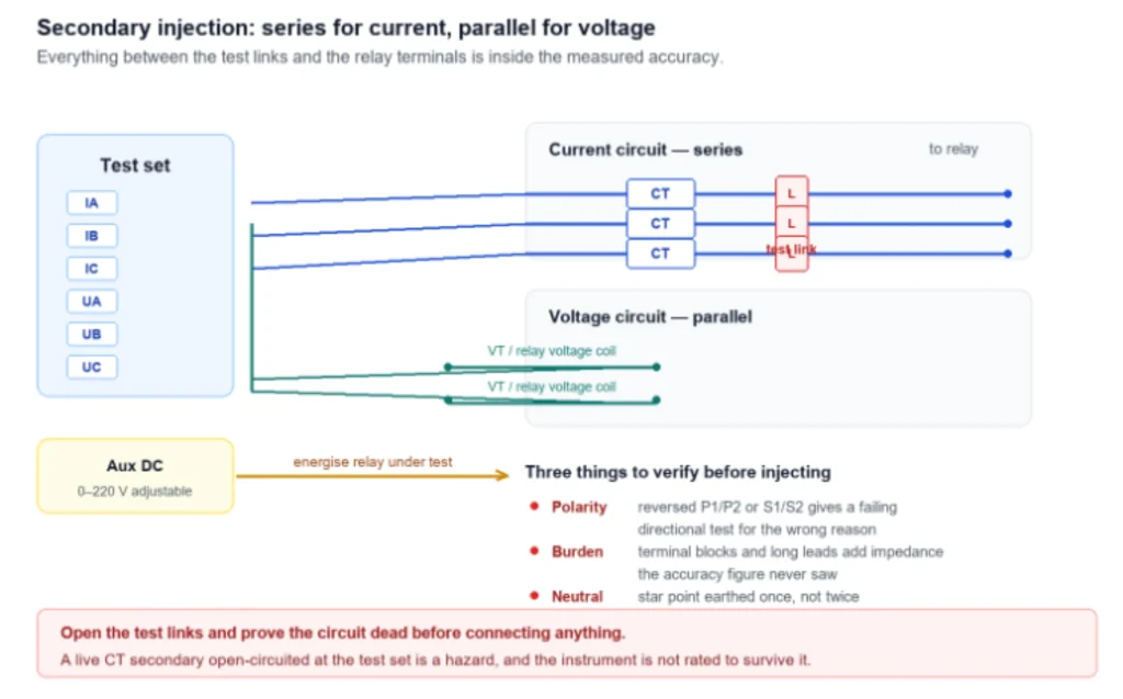
The safe sequence starts with isolation. Open the test links or terminal blocks that separate the relay current circuits from the current transformers, and prove the circuit is dead before connecting the set. A protection relay with a live CT secondary open-circuited is a hazard, and the test set is not rated to survive it.
Next, connect current sources in series with the relay current circuits and voltage sources in parallel with the voltage circuits, respecting polarity. Polarity errors are the single most common cause of a test that fails for the wrong reason: a directional element will refuse to operate, and the engineer will spend an hour adjusting settings before checking the marking on the terminal.
Then establish the reference condition. Set the ambient and the auxiliary supply to the values in the standard’s test reference conditions, note the calibration due date of the set, and record the relay’s firmware and settings version. Without those four data points the result is not reproducible, and a non-reproducible test cannot support a warranty or an insurance position.
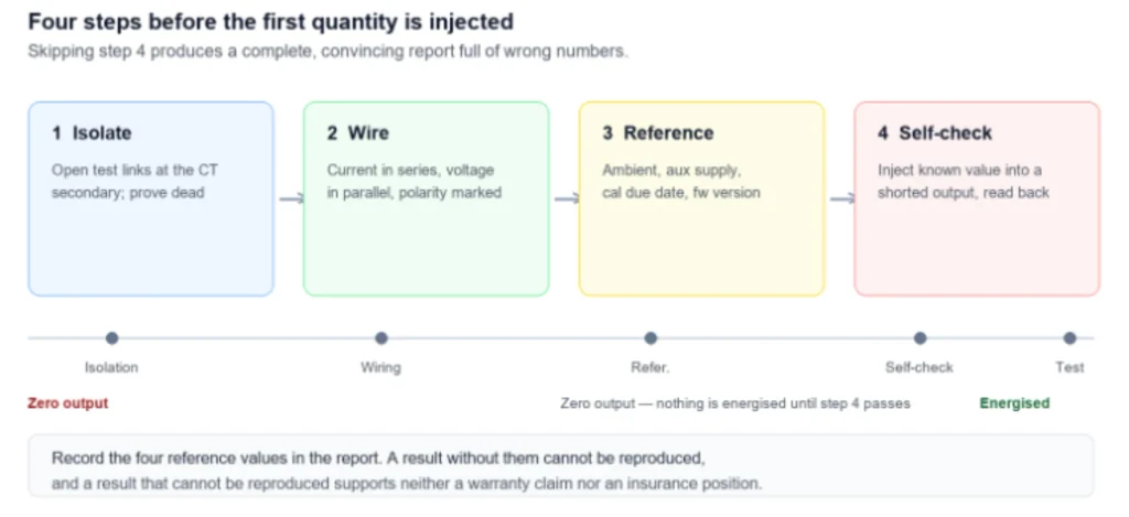
The final step is a self-check before testing the relay. Inject a known quantity into a shorted output and confirm the set reads what it should. A test set that has drifted will produce a beautiful report full of wrong numbers, and the drift will not appear anywhere in the results.
Limitations and boundaries
A test set verifies the relay, and only inside the conditions it can produce. The boundaries below are the ones that most often get lost between the test report and what the report is taken to prove.
Secondary injection does not test the current transformers, the voltage transformers, the secondary wiring between them and the relay, or the trip circuit from the relay contact to the breaker. Instrument transformers are covered separately in this guide to instrument transformer testing for ratio, polarity and burden. Those are separate tests with separate instruments, and a passing relay test says nothing about them. The same applies to cable and switchgear circuits on the same substation, which have their own cable testing and monitoring routine.
A test set cannot reproduce every primary condition. Saturation of a current transformer under a high-multiple fault, DC offset in the primary current, and the effect of remanence all change what the relay actually sees, and none of them can be generated by injecting into the secondary at the relay terminals.
Timing results are valid only within the tester’s own reference conditions. A set that is due for calibration, or that has been running for hours in a hot switch room, may be outside its stated accuracy band, and the report will not say so.
Finally, a passing test proves the relay operates as configured. It does not prove the configuration is correct for the network. That is a protection-setting study, and it is a different discipline from testing.
Frequently asked questions
How many channels does a set need?
Three current and three voltage channels cover feeder overcurrent, directional, distance and most motor protection, which is the majority of distribution work. Choose six current channels if transformer differential, busbar or generator protection is in scope, because those schemes require simultaneous currents from multiple windings or feeders that three channels cannot generate.
What is the difference between a fuse and relay tester and a relay test set?
A fuse and relay tester is an automotive or bench instrument that checks blade fuses and low-voltage relays with a go/no-go indication and no calibrated source. A relay test set is a protection instrument with specified amplitude and timing accuracy, programmable phase angles, sequencing and result recording, and it is the only one of the two that can produce a commissioning record.
How accurate should the timing measurement be?
A resolution of 1 ms and an accuracy of ±1 ms is adequate for time-graded overcurrent testing, where the grading margin between stages is usually far larger. Sub-cycle protection such as distance or high-speed differential needs better, and the specification should be read together with the timer’s own reference conditions rather than as a standalone figure.
Can I test a relay without disconnecting the current transformers?
No. The current circuits must be isolated from the CT secondary before the test set is connected, using test links or terminal blocks provided for the purpose. Connecting a test source into a live CT circuit is a safety hazard and will also produce meaningless results, because the CT will drive current into the test set.
Is automatic operation worth the extra cost?
It pays back when you test the same relay type repeatedly, typically more than about ten units a year, or when a quality system requires consistent traceable records. For a diverse installed base with a handful of each model, the engineering time to write and validate test plans usually exceeds the saving, and a manually operated set with good accuracy is the better buy.
What standards apply to relay testing?
IEC 60255-1:2022 sets the common requirements and test reference conditions for measuring relays and protection equipment, GB/T 7261-2016 gives the basic test methods for relaying protection and security automatic equipment in the Chinese system. IEEE C37.90.1-2024 covers surge withstand and fast transient immunity requirements for relays and their control devices.
Conclusion
Selecting one comes down to matching three things: the number of sources your protection schemes demand, the timing accuracy your test sheet tolerances require, and the amount of report automation your workload can justify. A six-channel set with 1 ms timing, operated by an engineer who understands the protection philosophy, will out-perform a twelve-channel set operated without one.
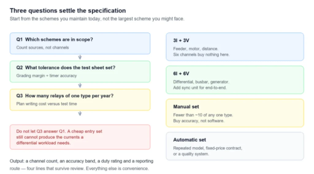
Start from the schemes you actually maintain, not from the largest scheme you might one day face. Confirm the continuous duty rating rather than the peak, check where the accuracy floor falls relative to your test points, and insist on an independent auxiliary supply if your relays need one.
Request a quotation for a relay tester matched to the relay models and protection schemes in your scope, and we will confirm the channel count, accuracy and reporting your commissioning work requires. Browse the full range of relay test sets and secondary injection instruments in the protective relay test category.
Technical references
1. IEC, IEC 60255-1:2022: Measuring relays and protection equipment — Part 1: Common requirements — webstore.iec.ch. 2. IEEE, IEEE C37.90.1-2024: IEEE Standard for Relays, Relay Systems, and Control Devices used for Protection and Control of Electric Power Apparatus — Surge Withstand Capability (SWC) and Electrical Fast Transient (EFT) Requirements and Tests — IEEE Xplore. 3. IEEE, IEEE C37.2-2022: IEEE Standard for Electrical Power System Device Function Numbers, Acronyms, and Contact Designations — standards.ieee.org. 4. SAC, GB/T 7261-2016: Basic testing method for relaying protection and security automatic equipment — openstd.samr.gov.cn.