

Author: Leon Zhang — Power monitoring and testing equipment team, Baoding Houfeng Trading Co., Ltd., specifying transformer test sets for substations, utilities and industrial plants
Technical review: this guide passed editorial review and was checked against IEEE C57.12.00-2021, IEEE 141-1993, IEC 60076-1:2011 and NFPA 70 (2026 edition) before publication
Last updated: 24 October 2026
Transformer calculator: A Practical Guide for Substation and Plant Engineers
A transformer calculator is a spreadsheet, a web page or a single function inside a design package that turns the numbers you already have — connected load, power factor, system voltage, number of phases — into the numbers you actually order against and test against: a kVA rating, a full-load current, a conductor size and a protection setting. The arithmetic underneath is four formulas and one table of standard ratings, which is why two calculators that disagree are almost always disagreeing about an input rather than about mathematics. This guide walks through what the calculation does, which single input moves the answer furthest, where the standard ratings come from, and how to check a result against the code and the standards before it becomes a purchase order or a setting sheet. It is written for the engineer specifying a new unit, and for the technician who has to decide whether the one already on site is big enough for what is about to be connected to it.
Key Takeaways
- The four outputs of every sizing tool — kVA rating, full-load current, conductor size and protection setting — come from four formulas and one lookup table; a transformer sizing calculator is simply the version that adds demand and growth factors in front of the first of them.
- Three-phase current is kVA × 1000 ÷ (√3 × line voltage), and at a 480 V bus the divisor collapses to 0.831, so a 750 kVA unit draws about 902 A. Single-phase current drops the √3, which more than doubles the answer for the same nameplate.
- Demand factor, diversity factor and load factor as defined in IEEE 141-1993 are the inputs that separate a defensible rating from a guess: the demand factor is the maximum coincident demand divided by the total connected load, and it is always 1 or less.
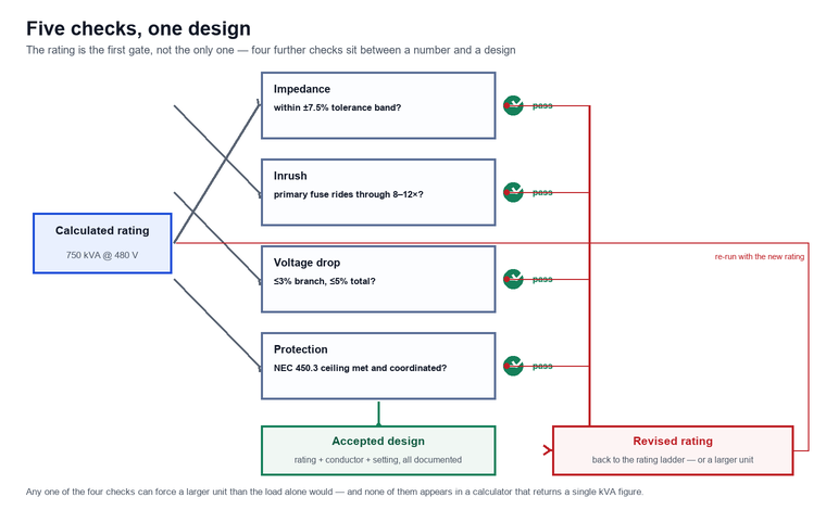
- A 3 phase transformer calculator that returns one number has answered the rating question only. Impedance, inrush and voltage drop each need their own pass, and any one of them can force a larger unit than the load alone would.
- Protection limits come from NEC 450.3: for a transformer with a primary over 1000 V, primary-only protection may reach 300% of primary full-load current, and adding secondary protection drops the primary limit to 250% (NFPA 70, Article 450.3).
- Every calculator output should be checked against the nameplate, the standard rating ladder and one field measurement — a turns-ratio reading taken from the installed unit settles any argument about the calculated ratio.
What a Transformer Calculator Actually Computes
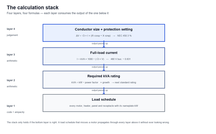
Ask a transformer calculator for a size and it returns one number, but ask it for a design and it returns four — the kVA rating the load requires, the full-load current at each winding voltage, the conductor size that carries that current within a voltage-drop limit, and the protection setting that keeps the transformer inside the code. The order matters, because each step consumes the output of the one before it, and an error in the first step propagates through all three without ever looking wrong.
Full-load current is the current a winding carries when the transformer is delivering its nameplate rating at its nameplate voltage, and it is the number every other calculation leans on. Get it wrong and the conductor is wrong, the protection is wrong, and the voltage-drop check is meaningless. Apparent power, measured in kVA, is the vector sum of real power in kW and reactive power in kvar, which is why a plant can have 504 kW of real demand and still need a 560 kVA transformer. Turns ratio is the primary-to-secondary voltage ratio of the winding set, and it is fixed by the nameplate — a calculator can predict it, but only a measurement on the installed unit confirms it.
What the calculator does not compute is equally important. It does not size for short-circuit duty, it does not derate for harmonics, it does not correct for altitude or ambient temperature, and it does not check whether the primary fuse will ride through magnetising inrush. Those are separate passes, and on a site with variable-frequency drives or a long feeder they are the passes that change the answer.
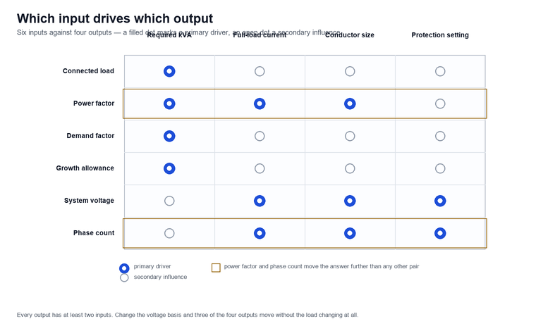
The inputs are worth one more sentence, because they are where the real work is. Connected load comes from a load schedule — every motor, heater, panel and receptacle with its nameplate rating — and it is only as complete as the discipline of whoever compiled it. Power factor comes from the load itself: induction motors sit near 0.85 lagging at full load and fall away sharply when they run lightly loaded, while resistive heating and modern lighting sit close to unity. System voltage comes from the utility’s nominal figure, and the phase count comes from the service. None of the four is a property of the transformer, which is exactly why two people can run the same tool on the same project and get answers 30 percent apart.
The Four Formulas Behind the Arithmetic
Strip away the interface and there are four formulas, and everything else in the tool is bookkeeping around them — unit conversions, dropdown lists, the standard rating table and the rounding rule that turns a calculated capacity into an orderable nameplate.
The first converts real power to apparent power, because transformers and conductors are rated in apparent power while load schedules are usually written in kilowatts:
- kVA = kW ÷ power factor
The second and third are the current formulas, and the only difference between them is the √3:
- Single phase: I = (kVA × 1000) ÷ V
- Three phase: I = (kVA × 1000) ÷ (√3 × V)
The fourth is the turns ratio, which ties the two winding voltages and the two winding currents together:
- V_primary ÷ V_secondary = N_primary ÷ N_secondary = I_secondary ÷ I_primary
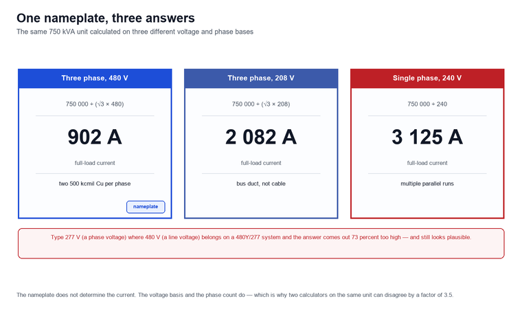
Two practical consequences follow immediately. First, at a 480 V three-phase bus the √3 × 480 product is 831.4, so the divisor becomes 0.831 and the mental arithmetic is just kVA ÷ 0.831: 300 kVA is 361 A, 500 kVA is 601 A, and 750 kVA is 902 A. Second, the same nameplate at a different voltage or phase count gives a completely different current, which is the single most common source of disagreement between two people comparing results.
The voltage-drop calculation is the fifth formula, and it is the one that decides conductor size once the current is known:
- ΔV = √3 × I × (R × cos φ + X × sin φ)
Power factor is the cosine of the phase angle between voltage and current, and it appears twice in that expression — once directly and once through the sine — which is why a plant running at 0.80 lagging needs a larger transformer for the same kilowatts than one running at 0.95.
The first formula deserves a moment, because it is the one most often skipped by people who start from a load schedule written in amperes. If the schedule is in kilowatts — and most are — the division by power factor is not optional: it is the step that accounts for the magnetising and leakage reactive power the transformer has to supply in addition to the real power the load consumes. Skipping it undersizes the unit by exactly the reciprocal of the power factor, so a 560 kVA requirement calculated as 504 kW becomes a 504 kVA purchase, and the unit runs hot on a load it was never rated for. The correction runs the other way as well: a site with power-factor correction capacitors installed downstream of the transformer presents a higher power factor at the primary than at the load, and the rating calculation should use the power factor at the transformer terminals rather than the one printed on the motor nameplates.
Transformer Sizing Calculator: From Connected Load to Nameplate
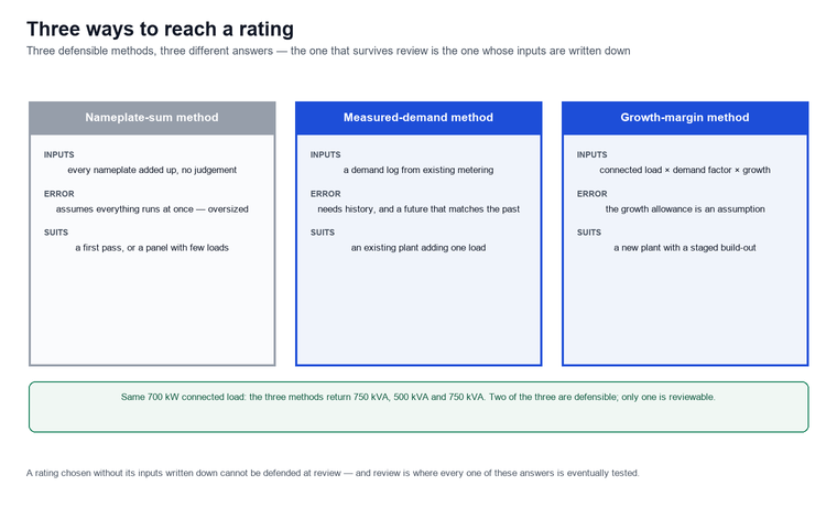
This is where a transformer sizing calculator earns its keep, because the step from a nameplate sum to a defensible rating is judgement dressed as arithmetic, and the judgement has to come from somewhere.
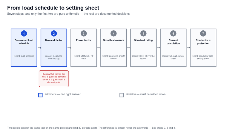
The method is the same in every tool. Start from the total connected load in kilowatts. Multiply by a demand factor to get the maximum coincident demand in kilowatts. Divide by the power factor to get kVA. Multiply by a growth allowance. Round up to the next standard rating. Consider a worked example, because it makes the size of each step visible and shows where the judgement is hiding:
| Step | Input | Value |
|---|---|---|
| 1 | Total connected load | 700 kW |
| 2 | Demand factor | 0.72 |
| 3 | Maximum coincident demand | 504 kW |
| 4 | Power factor | 0.90 |
| 5 | Required capacity | 560 kVA |
| 6 | Growth allowance | 25 percent |
| 7 | Design capacity | 700 kVA |
| 8 | Next standard rating | 750 kVA |
| 9 | Full-load current at 480 V | 902 A |
Row 2 is the row that carries the risk. Demand factor is the ratio of the maximum coincident demand of a system to the total connected load of that system, and it is always 1 or less; IEEE 141-1993 notes it commonly falls between 0.8 and 1 but can drop to 0.15 to 0.25 in plants with very low diversity. A demand factor taken from a rule of thumb instead of from a load log is a guess with a decimal point on it, and it is the reason a calculator result should always be cross-checked against a measured demand where metering exists.
Two companion factors appear alongside it. Diversity factor is the ratio of the sum of the individual non-coincident maximum demands of the subdivisions of a system to the maximum demand of the complete system, and it is always 1 or greater — it is the factor that explains why adding a second panel does not double the transformer. Load factor is the ratio of the average load over a designated period to the peak load in that period, and it governs losses and thermal ageing rather than the nameplate: a unit loaded to 750 kVA for two hours a day and 200 kVA for the rest is not thermally equivalent to one loaded at 750 kVA continuously, even though the rating calculation treats them identically.
Transformer Size Calculator: Choosing Among Standard Ratings
Once the design capacity is known, a transformer size calculator has very little left to decide, but what it decides is expensive in both directions, because the rating it lands on sets the efficiency class, the bus and cable sizes and the protection scheme for the life of the installation.
Ratings are standardised so that a unit drops into an existing pad, onto an existing cable and into an existing protection scheme. The standard three-phase ratings run 75, 112.5, 150, 225, 300, 500, 750, 1 000, 1 500, 2 000 and 2 500 kVA, continuing to 10 MVA inside the IEEE C57.12.34-2022 scope, and the rule is to take the next standard rating above the design capacity rather than the nearest one below. The example above lands on 750 kVA, which also happens to be the rating at which the low-voltage compartment bus and the service conductors stop being trivial.
Oversizing is not free. Federal conservation standards in 10 CFR 431.196 set a minimum efficiency at half of nameplate load for three-phase liquid-immersed units manufactured on or after 1 January 2016 and before 23 April 2029, and the minimum rises from 99.03% at 75 kVA through 99.27% at 300 kVA and 99.35% at 500 kVA to 99.53% at 2 500 kVA (10 CFR 431.196). At 500 kVA the half-load loss of a compliant unit is about 1.6 kW, and a unit two percentage points less efficient wastes about 6.8 kW at the same load — a permanent cooling penalty inside a sealed cabinet, paid for in capital and in energy for the life of the unit. Undersizing, by contrast, costs a second unit, a second pad and a second outage, which is almost always the more expensive mistake.
The ladder itself is worth having in front of you when the calculated capacity lands between two ratings, because the step you take up is the step the bus, the cable and the protection all have to live with:
| Standard rating | Full-load current at 480 V | Where the step usually lands |
|---|---|---|
| 75 kVA | 90 A | lighting and small receptacle panels |
| 150 kVA | 181 A | small process skid or single compressor |
| 300 kVA | 361 A | one large chiller or a machine shop feeder |
| 500 kVA | 601 A | mid-size plant section, half-load loss about 1.6 kW |
| 750 kVA | 903 A | the worked example above |
| 1 000 kVA | 1 204 A | multi-panel industrial feeder |
| 2 500 kVA | 3 009 A | plant main, top of the common range |
3 Phase Transformer Calculator: The √3 Factor and Why It Trips People Up
Most arguments about a 3 phase transformer calculator are arguments about the √3, and most of those turn out to be arguments about which voltage was typed into the box — the line voltage or the phase voltage, which on a 480Y/277 system differ by a factor of 1.73.
In a three-phase system the √3 converts between line and phase quantities. On a delta winding the line voltage equals the phase voltage and the line current is the phase current times √3; on a wye winding the line voltage is the phase voltage times √3 and the line current equals the phase current. The current formula uses the line voltage, because that is what the nameplate prints and what the busbars carry. Type in a phase voltage instead — 277 instead of 480 on a 480Y/277 system — and the answer comes out 73 percent too high, an error that still looks like a plausible current and that survives a casual review.
The same nameplate therefore produces four different currents depending only on the voltage and phase basis:
| Basis | Formula | Current for 750 kVA |
|---|---|---|
| Three phase, 480 V | 750 000 ÷ (√3 × 480) | 902 A |
| Three phase, 208 V | 750 000 ÷ (√3 × 208) | 2 082 A |
| Single phase, 480 V | 750 000 ÷ 480 | 1 563 A |
| Single phase, 240 V | 750 000 ÷ 240 | 3 125 A |
Two further traps live in the same territory. The first is the single-phase bank: three IEEE C57.12.38-2025 cabinets fed phase-to-neutral give the utility a spare that fits in a pickup truck, but the current through each unit is the single-phase figure, not the three-phase one, and an open-delta configuration left behind by a failed unit runs at about 58 percent of the original bank capacity. The second is the connection symbol: a delta-wye unit with a 13.8 kV delta primary and a 480Y/277 wye secondary has a 30-degree phase displacement that a vector-group check will find and a calculator will not mention.
The Numbers a Calculator Leaves Out
The rating answer is the easy part, and three further checks decide whether the unit that satisfies the load also satisfies the network — a tool that returns only a kVA figure has not attempted any of them, and any one of the three can force a larger unit than the load alone would.
Impedance is the first. Percent impedance is the per-unit voltage drop across the winding at rated current, and it sets both the through-fault current and the voltage dip. IEEE C57.12.00-2021 allows a tolerance of plus or minus 7.5% (IEEE C57.12.00-2021) on the measured impedance voltage of a two-winding transformer, so a unit stamped 5.75% can legitimately measure anywhere in a band of roughly 5.3% to 6.2% and still be inside the standard (IEEE C57.12.00-2021). On the infinite-bus assumption the same unit passes about 17.4 times its full-load current into a bolted fault, which at 902 A is roughly 15.7 kA — and that is the number the downstream switchgear has to interrupt, not the full-load current.
Magnetising inrush is the second. On energisation, a transformer draws an asymmetric first-cycle current commonly eight to twelve times rated current, decaying over a few cycles — for a 750 kVA unit at 480 V that is roughly 7.2 kA to 10.8 kA on the first peak, which is why the primary fuse is a coordination decision rather than a current rating and why a fuse that has operated on a healthy unit is an inrush question before it is a fault question.
Two further effects sit outside the rating arithmetic altogether. Ambient temperature and altitude both reduce the thermal margin: a unit rated at 30 °C ambient and 1 000 m does not deliver its nameplate at 45 °C and 2 500 m without a derating that the manufacturer states and the calculator does not model, and IEC 60076-1:2011 is the document that defines how the correction is applied. Motor starting is the other: a 200 hp motor on the secondary draws six to eight times its full-load current for the duration of the start, and while that is a voltage-dip question rather than a transformer-rating question, the dip is what the lighting and the drives on the same bus actually notice.
Voltage drop is the third, and it is the one that most often forces a conductor change rather than a rating change. For example, take the worked example further: a 250 ft one-way feeder carrying 902 A at 0.90 power factor with three parallel 500 kcmil copper conductors per phase has a resistance of about 0.0026 Ω and a reactance of about 0.004 Ω, giving ΔV = √3 × 902 × (0.0026 × 0.90 + 0.004 × 0.436) ≈ 6.4 V, or about 1.3% of the 480 V bus — inside the 3% branch-circuit and 5% total guidance in the informational notes to NEC 210.19(A) and 215.2(A) (NFPA 70). Halve the conductor count or double the run and the same arithmetic moves the answer outside the guidance without changing the transformer rating at all.
The three checks sit side by side like this, and none of them appears in a tool that stops at the kVA figure:
| Check | What it decides | Where the number comes from |
|---|---|---|
| Impedance | through-fault current and the voltage dip at the bus | nameplate percent impedance, measured within ±7.5% (IEEE C57.12.00-2021) |
| Magnetising inrush | whether the primary fuse holds on energisation | 8–12× rated current on the first peak, decaying over a few cycles |
| Voltage drop | conductor size and bus voltage under load | ΔV = √3 × I × (R × cos φ + X × sin φ) |
Checking the Answer Against the Standards
A calculator output is a proposal, and the standards are what turn it into a design — four documents are worth reading against the result, and each one closes a different gap that the arithmetic leaves open.
NEC Article 450 governs transformer protection in the United States, and its two tables are the reason a protection setting is not simply the full-load current. For a transformer with a primary over 1000 V, primary-only protection — a fuse or a breaker on the primary — may be rated up to 300% of primary full-load current; adding secondary protection drops the primary limit to 250% and caps the secondary device at 250% as well. For transformers at 1000 V or less, Table 450.3(B) is stricter: primary-only protection is limited to 125% of primary full-load current (NFPA 70, Table 450.3(B)), with the next higher standard size permitted where the calculated value does not correspond to a standard rating, and combined primary and secondary protection permits 250% on the primary against a secondary device at 125% where both currents are 9 A or more. On the 750 kVA example the secondary full-load current of 902 A gives a 1 128 A maximum, so a 1 200 A device, and the 13.8 kV primary full-load current of 31.4 A gives a 94 A primary fuse under the 300% rule — which is exactly where the utility’s own inrush coordination practice usually overrides the arithmetic, and why the fuse curve has to be checked against the eight-to-twelve-times inrush band rather than against the current alone.
IEEE 141-1993, the Red Book, remains the reference most load schedules still cite for demand, diversity and load factor, and IEEE 241-1990, the Gray Book, carries the equivalent guidance for commercial buildings. Both are listed by IEEE as inactive-reserved standards since March 2021, which means they are no longer maintained but are still the documents that most project specifications name; where a specification cites them, the calculator inputs should be traceable to their definitions rather than to a spreadsheet default.
IEC 60076-1:2011 is the international counterpart for rating, tolerances and testing of power transformers, and it is the document that defines the tolerance band within which a measured ratio or resistance is acceptable. IEEE C57.12.34-2022 and IEEE C57.12.38-2025 cover the three-phase compartmental and single-phase distribution families that most plant-level units belong to, and IEEE C57.152-2025 is the diagnostic testing guide that says results should be interpreted together rather than one at a time.
Read against a calculated result, the four documents divide the work like this:
| Check | Governing document | Acceptance criterion | What a transformer calculator returns |
|---|---|---|---|
| Impedance | IEEE C57.12.00-2021 | measured impedance within ±7.5% of nameplate | nothing — a factory or field test |
| Magnetising inrush | fuse curve against the inrush band | primary device rides through 8–12× rated current | nothing — a coordination study |
| Voltage drop | informational notes to NEC 210.19(A) and 215.2(A) | 3% branch circuit, 5% total | a conductor size, not a drop figure |
| Protection | NEC 450.3, Tables 450.3(A) and 450.3(B) | 300% / 250% / 125% ceilings by voltage class | a percentage applied to full-load current |
Field Use: Verifying What the Calculator Predicted
The calculation is finished when the unit is on site, and the site is where it is proved — four measurements close the loop, and each one maps onto a formula above, so a wrong assumption in the spreadsheet shows up as a wrong reading in the field.
A turns-ratio measurement on every tap confirms the ratio the calculator predicted and catches an open turn, a wrong tap position and a mislabelled bushing in one pass; the HF-TC-601 transformer turns ratio tester covers 0.9 to 10 000 with 0.1 percent accuracy, which spans a 34.5 kV to 480 V unit comfortably. A DC winding-resistance measurement, corrected to a reference temperature, confirms the conductor path that the conductor-size step assumed and finds loose connections and broken strands; the HF-TC-602 transformer DC winding resistance tester runs six current steps to 10 A across 500 μΩ to 50 kΩ. On a unit with an on-load tap changer, the HF-TC-604 transformer load tap changer analyzer records the transition waveform that a static ratio reading cannot show. Where the question is the switchgear rather than the winding, the HF-TC-612 handheld loop resistance tester measures the assembled contact path that the protection step assumed to be negligible.
On one 750 kVA, 13.8 kV to 480 V unit at a food plant, the sizing sheet carried a 0.72 demand factor taken from a rule of thumb, and the calculated 902 A full-load current was used to set both the secondary breaker and the feeder. A power quality analyzer logged for two weeks showed real peak demand at 31 percent of connected load — the plant ran one shift with staggered starts — so the measured demand factor came out nearer 0.31 than 0.72. The unit was not oversized by judgement; it was oversized by an assumption, and the logging paid for itself the first time it stopped the same assumption being carried into the next expansion.
The wider condition picture sits alongside these. For instance, the transformer monitoring work that follows a new unit into service, the instrument transformer testing programme that keeps the measurement chain honest, and the cable testing and monitoring that covers the conductors the current step sized all use the same numbers the calculator produced, which is the practical reason to keep the calculation sheet with the test records rather than in a separate folder. The IEC 60599:2022 DGA guide is the reference for reading the oil once the unit is energised, and the power quality analyzer is the instrument that produces the measured demand that should replace the assumed demand factor the next time the calculation is run. A ground resistance tester closes the loop on the earthing that the protection step assumed.
Limitations and Boundaries
The calculation is a sizing aid, not a design, and four boundaries are worth stating explicitly, because each one describes a case where the tool returns a confident answer that is wrong and the site pays for it later.
- It assumes a balanced three-phase load with a single power factor. A plant with single-phase lighting and process loads mixed on the same bus, or with large single-phase welding loads, will have a phase imbalance the calculation never sees.
- It does not account for harmonics. Variable-frequency drives, LED lighting and rectifier loads draw non-sinusoidal current that heats a winding more than the fundamental current alone, and the K-factor or the harmonic spectrum has to be applied separately.
- It does not perform a short-circuit or motor-starting study. The rating it produces may be perfectly adequate for the load and still be inadequate for the fault duty or the voltage dip at the bus.
- It does not check the protection coordination. The 300%, 250% and 125% limits from NEC 450.3 are maximums, not targets, and the fuse curve or breaker setting has to be coordinated with inrush and with the downstream devices separately.
FAQ
What is this kind of tool used for?
The tool converts a load description into equipment ratings: it turns connected load, power factor and system voltage into a kVA rating, a full-load current at each winding, a conductor size and a protection setting. It is used at design stage to select a unit, at review stage to check someone else’s selection, and at commissioning stage to predict the currents that the field instruments should then confirm.
How accurate is the calculation?
The arithmetic is exact; the inputs are not. A calculator is as accurate as its power factor, demand factor and voltage basis, and a single wrong input — a phase voltage typed where a line voltage belongs, or a demand factor assumed rather than measured — produces an answer that looks entirely reasonable. Treat the output as a proposal to be checked against a nameplate, a measured demand and one field measurement, not as a result.
What is the difference between kVA and kW in transformer sizing?
Kilowatts measure real power delivered to the load; kilovolt-amperes measure apparent power, which is the real power plus the reactive power the magnetic circuit needs. Transformers, conductors and switchgear are rated in kVA, so the sizing calculation divides the kilowatt load by the power factor to reach the rating. A plant drawing 504 kW at 0.90 power factor needs 560 kVA of capacity, not 504 kVA.
How do I calculate transformer full load current?
For a three-phase transformer, divide kVA × 1000 by √3 times the line voltage; for a single-phase transformer, divide kVA × 1000 by the voltage. At 480 V three-phase the divisor is 0.831, so a 500 kVA unit is 601 A and a 750 kVA unit is 902 A. Always use the line voltage on the nameplate, not the phase voltage, and always state the phase count alongside the answer.
What demand factor should I use for transformer sizing?
Use a measured one if metering exists. Where it does not, IEEE 141-1993 gives the definition and the range: the ratio of maximum coincident demand to total connected load, commonly between 0.8 and 1 but falling to 0.15 to 0.25 in plants with very low diversity. A value chosen from a rule of thumb for a plant whose load profile nobody has measured is the most common source of an oversized or undersized unit.
Can the calculation size the protection as well?
It can apply the NEC 450.3 percentages to the full-load current it just calculated, but that is a ceiling rather than a setting. The fuse curve or breaker characteristic still has to be coordinated with magnetising inrush, with the downstream devices and with the utility’s practice on the primary side, and on a medium-voltage primary the inrush coordination usually decides the rating rather than the current arithmetic.
Why does my transformer calculator give a different answer from the nameplate?
Because the nameplate current is a fact and the calculated current is a prediction. They differ when the power factor, demand factor, voltage basis or phase count in the calculation does not match the installed conditions, and they also differ legitimately when the calculation includes a growth allowance the nameplate obviously does not. The nameplate wins on an installed unit; the calculation wins on a unit that does not exist yet.
Conclusion
A transformer calculator is four formulas, one table of standard ratings and a set of documented assumptions. The formulas are not where the risk lives; the assumptions are. Write down the power factor, the demand factor, the growth allowance and the voltage basis alongside the answer, and the result becomes reviewable — which is the difference between a number and a design.
For the field side of the same question, the transformer tester category covers the instruments that confirm a calculated ratio, a calculated current and a calculated protection setting on an installed unit, including the HF-TC-601 turns ratio tester, the HF-TC-602 DC winding resistance tester, the HF-TC-604 load tap changer analyzer and the HF-TC-612 handheld loop resistance tester. If you are specifying a unit and want the calculation checked against your load log, contact us — we would rather argue about the demand factor before the unit is on the pad than after.
References and Technical Sources
- IEEE, IEEE Recommended Practice for Electric Power Distribution for Industrial Plants (Color Book series), IEEE 141-1993, published 29 April 1994, reaffirmed 1999, inactive-reserved since 25 March 2021 — demand, diversity and load factor definitions. standards.ieee.org
- IEEE, IEEE Recommended Practice for Electric Power Systems in Commercial Buildings (Color Book series), IEEE 241-1990, published 18 September 1991, reaffirmed 1997, inactive-reserved since 25 March 2021 — commercial load characteristics. standards.ieee.org
- IEEE, IEEE Standard for General Requirements for Liquid-Immersed Distribution, Power and Regulating Transformers, IEEE C57.12.00-2021 — impedance tolerance and inrush basis. standards.ieee.org
- IEEE, IEEE Standard for General Requirements for Liquid-Immersed Distribution, Power and Regulating Transformers — compartmental-type three-phase units, IEEE C57.12.34-2022 — standard ratings to 10 MVA. standards.ieee.org
- IEEE, IEEE Standard for Pad-Mounted-Type, Self-Cooled, Single-Phase Distribution Transformers 250 kVA and Smaller, IEEE C57.12.38-2025 — single-phase pad-mounted units to 250 kVA. standards.ieee.org
- IEEE, IEEE Guide for Diagnostic Field Testing of Liquid-Filled Power Transformers, Regulators, and Reactors, IEEE C57.152-2025 — interpreting results together. standards.ieee.org
- IEC, Power transformers — Part 1: General, IEC 60076-1:2011, edition 3.0, published 20 April 2011 — rating, tolerances and testing. webstore.iec.ch
- IEC, Mineral oil-filled electrical equipment in service — Guidance on the interpretation of dissolved and free gases analysis, IEC 60599:2022, edition 4.0, published 25 May 2022 — in-service gas interpretation. webstore.iec.ch
- NFPA, NFPA 70, National Electrical Code, 2026 edition — Article 450 transformer protection; informational notes to 210.19(A) and 215.2(A) on voltage drop. nfpa.org
- U.S. Government Publishing Office / eCFR, Energy Conservation Program: Energy Conservation Standards for Distribution Transformers, 10 CFR 431.196 — minimum efficiency at half load. ecfr.gov
- NIST, Applied Electrical Metrology — measurement traceability for current, voltage and ratio calibration. nist.gov