

Introduction
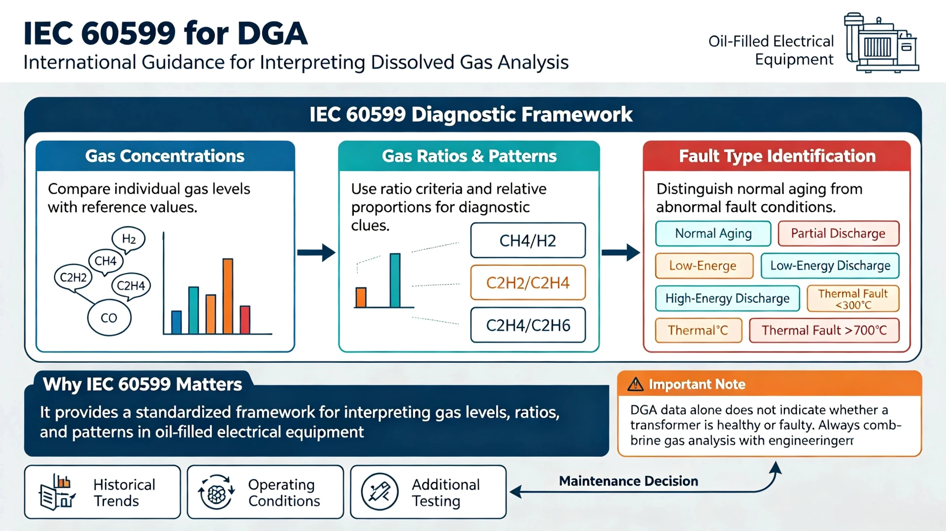
IEC 60599 provides guidance for interpreting dissolved gas analysis results from mineral-oil-filled electrical equipment. It helps engineers relate dissolved gas patterns to possible thermal and electrical fault conditions.
IEC 60599 transformer DGA is not a measurement method itself — it is an interpretation framework. It defines how dissolved gas data should be evaluated, what gas ratios and concentration levels are typically associated with different fault types, and how those findings should be applied in transformer fault diagnosis.
The standard addresses a practical problem: dissolved gas data alone does not indicate whether a transformer is healthy or faulty. IEC 60599 DGA provides structured criteria for distinguishing normal aging from abnormal conditions such as partial discharge, electrical discharge, and thermal faults. It applies primarily to oil-filled power transformers and similar electrical equipment filled with mineral insulating oil.
Within the broader DGA diagnostic landscape, IEC 60599 serves as a foundational reference, alongside methods such as the Duval Triangle, Rogers Ratios, and Key Gas Method. It does not replace those methods — it provides the standard framework within which they are applied.
What Is IEC 60599 for DGA?
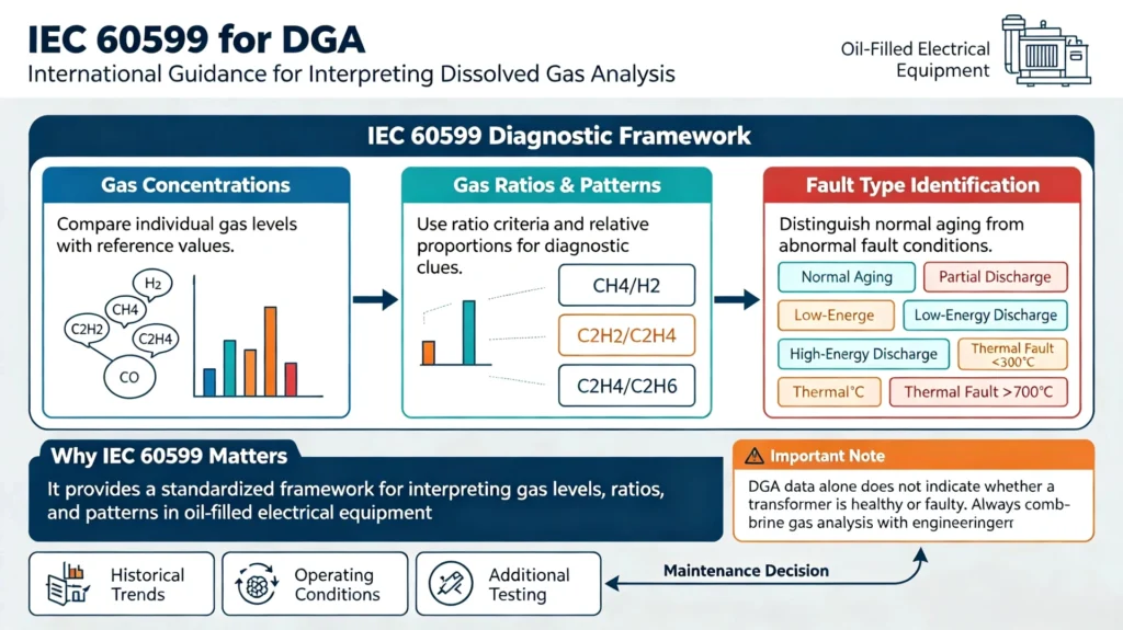
IEC 60599 is an international standard that provides guidance for interpreting dissolved gas analysis results from oil-filled electrical equipment. It helps engineers relate dissolved gas patterns to possible thermal and electrical fault conditions.
DGA data alone does not indicate whether a transformer is healthy or faulty. A diagnostic standard is needed to define what gas levels, ratios, and patterns typically mean. IEC 60599 dissolved gas analysis provides this framework — it establishes criteria for distinguishing normal aging from abnormal conditions such as partial discharge, electrical discharge, and thermal faults.
The table below summarizes the standard’s role:
| Item | Description |
|---|---|
| Standard | IEC 60599 |
| Application | Dissolved Gas Analysis |
| Main purpose | Interpretation of dissolved gases |
| Equipment | Oil-filled electrical equipment |
| Diagnostic focus | Thermal and electrical fault conditions |
| Output | Diagnostic indications, not a standalone failure prediction |
IEC 60599 supports DGA interpretation; it does not by itself provide a complete prediction of when a transformer will fail. It is a diagnostic framework that helps engineers organize gas data into meaningful fault categories — which can then be combined with historical trends, operating conditions, and other diagnostic methods.
Within the broader DGA landscape, IEC 60599 serves as a foundational reference alongside methods such as the Duval Triangle, Rogers Ratios, and Key Gas Method.
Scope of IEC 60599 DGA
IEC 60599 transformer DGA provides guidance on interpreting dissolved gas analysis results for mineral-oil-filled electrical equipment in service. Its scope is defined by equipment type, the data it covers, and the boundaries of its diagnostic role.
Applicable Equipment
IEC 60599 applies to electrical equipment filled with mineral insulating oil and insulated with cellulosic paper or pressboard-based solid insulation. The standard provides specific application notes for equipment types including power transformers, instrument transformers, industrial transformers, railway transformers, distribution transformers, reactors, bushings, switchgear, and oil-filled cables. However, information for these specific equipment types is given only as an indication in the application notes — the standard’s core framework applies broadly to mineral-oil-filled equipment.
It may also be applied with caution to other liquid-solid insulating systems, but the indications obtained are given only as guidance, with resulting action undertaken only with proper engineering judgment.
What IEC 60599 Covers
The standard covers the interpretation of dissolved and free gas concentrations to diagnose the condition of oil-filled electrical equipment and suggest future action. Its scope includes:
- DGA interpretation using gas concentrations and gas generation rates
- Diagnostic approaches for identifying thermal and electrical fault conditions
- Typical gas concentration values and rates of gas increase
- Interpretation of abnormal gas patterns
The interpretation process described in IEC 60599 typically involves comparing individual gas contents with typical values, checking rates of gas increase, and applying gas ratio methods when abnormalities are detected.
What IEC 60599 Does Not Determine
IEC 60599 does not replace engineering judgment, laboratory confirmation, or other transformer diagnostic tests. The indications obtained are given only as guidance, and any resulting action should be undertaken only with proper engineering judgment. The standard does not provide a definitive diagnosis on its own — it supports structured interpretation of gas data, which must then be combined with historical trends, operating conditions, and additional testing before maintenance decisions are made.
How IEC 60599 Is Used for Dissolved Gas Analysis
IEC 60599 uses a structured, multi-step approach that moves from raw gas measurements to a possible fault classification. The overall logic follows this sequence:
DGA Measurement
↓
Gas Concentration
↓
Gas Generation Rate
↓
Gas Pattern
↓
Diagnostic Method
↓
Possible Fault Type
↓
Engineering Assessment
DGA Data Collection
IEC 60599 interpretation starts with reliable dissolved gas measurements. The standard applies to mineral-oil-filled electrical equipment in service and provides guidance on interpreting both dissolved and free gas concentrations . Without accurate gas concentration data, the subsequent steps cannot produce meaningful results.
Gas Concentration Assessment
The first diagnostic step compares individual gas concentrations against typical reference values. IEC 60599 establishes concentration thresholds for individual gases, providing specific action levels that trigger investigation or intervention . For example, acetylene concentrations above 35 ppm typically indicate serious arcing conditions requiring urgent attention . The standard also provides typical 90% concentration values observed in service for different equipment types, including power transformers, instrument transformers, and bushings .
Gas Generation Trends
A single DGA result provides only a snapshot. IEC 60599 also considers rates of gas increase, which can indicate whether a condition is stable, developing, or accelerating. The standard provides typical rates of gas increase observed in service for power transformers (all types) . Trend analysis helps distinguish between normal aging, transient fluctuations, and a developing fault condition.
Gas Ratios and Diagnostic Methods
When gas concentrations or generation rates indicate an abnormality, IEC 60599 applies gas ratio analysis to classify the fault type. The standard employs three key ratios: C₂H₂/C₂H₄, CH₄/H₂, and C₂H₄/C₂H₆ . These ratios create distinct fault categories that enable systematic diagnosis of thermal faults, partial discharge, and arcing conditions . Additional ratios such as CO₂/CO and C₂H₂/H₂ are suggested for specific fault cases .
The standard also references graphical methods such as the Duval Triangle for specific equipment types, including Duval Triangle 2 for OLTCs .
Fault Classification
IEC 60599 categorizes faults into five main types that can be reliably identified by visual inspection after a fault has occurred :
- PD — Partial discharges of the cold plasma (corona) type, with possible X-wax formation
- D1 — Low-energy discharges, evidenced by small carbonized punctures in paper
- D2 — High-energy discharges, evidenced by extensive carbonization, metal fusion, and possible tripping
- T1 — Thermal faults below 300°C, where paper has turned brownish
- T2 — Thermal faults between 300°C and 700°C, where paper has carbonized
- T3 — Thermal faults above 700°C, evidenced by oil carbonization, metal coloration, or fusion
The standard also describes a combined thermal and electrical fault category (DT) in some interpretations .
Engineering Assessment
The final step is engineering assessment. IEC 60599 explicitly states that the indications obtained are given only as guidance, with resulting action undertaken only with proper engineering judgment . The standard does not replace laboratory confirmation, electrical testing, or other diagnostic methods. It provides a structured framework for interpreting gas data, which must then be combined with historical trends, operating conditions, and additional testing before maintenance decisions are made.
IEC 60599 DGA Interpretation
IEC 60599 DGA interpretation is a structured process that moves from individual gas measurements to a possible fault classification. The standard provides guidance on how dissolved gas concentrations should be evaluated, not just reported.
Interpreting Dissolved Gas Concentrations
Gas concentration tells engineers how much of a specific gas is present in the oil. IEC 60599 provides typical 90% concentration values observed in service for different equipment types, helping distinguish between normal and abnormal levels . The standard also establishes alarm concentration values that trigger investigation .
However, concentration alone is not enough. A gas level within typical limits does not automatically mean the transformer is healthy, and an elevated level does not confirm a fault. Concentration must be evaluated together with gas generation rates, gas ratios, and operating history.
Evaluating Gas Generation Rates
IEC 60599 considers rates of gas increase as a key diagnostic input. The standard provides typical rates of gas increase observed in power transformers, expressed in µl/l/year . A gas concentration that is moderate but rising rapidly may indicate a developing fault more clearly than a higher but stable concentration.
This is where IEC 60599 interpretation connects directly with DGA Fault Detection: rate-of-change data helps identify whether a condition is stable, developing, or accelerating.
Identifying Gas Patterns
Certain combinations and relative proportions of dissolved gases can indicate different fault categories. IEC 60599 uses three key gas ratios — C₂H₂/C₂H₄, CH₄/H₂, and C₂H₄/C₂H₆ — to classify faults into categories including partial discharge (PD), low-energy discharge (D1), high-energy discharge (D2), and thermal faults (T1, T2, T3) . Additional ratios such as CO₂/CO are suggested for specific fault cases .
Combining Gas Data With Operating History
IEC 60599 emphasizes that DGA results should not be interpreted in isolation. The standard states that indications obtained are given only as guidance, and any resulting action should be undertaken only with proper engineering judgment .
Transformer load, temperature, maintenance activities, switching events, and previous DGA results all provide context that can explain gas behavior or confirm a developing condition. Combining gas data with operating history improves diagnostic accuracy and supports sound maintenance decisions.
IEC 60599 Transformer Fault Diagnosis
IEC 60599 transformer fault diagnosis provides a structured framework for interpreting DGA patterns and classifying possible fault types. The standard groups faults into general diagnostic categories:
| Fault Category | General Diagnostic Meaning |
|---|---|
| Partial discharge | Low-energy electrical activity |
| Electrical discharge | Higher-energy electrical activity |
| Thermal fault | Abnormal heating |
| Thermal fault involving insulation | Thermal stress associated with oil/paper insulation |
Partial Discharge
IEC 60599 provides a framework for interpreting DGA patterns that may be associated with partial discharge activity. This category covers low-energy electrical activity, often characterized by elevated hydrogen and methane. The standard does not confirm partial discharge — it indicates that the gas pattern is consistent with this type of condition.
Electrical Discharge
IEC 60599 distinguishes between lower-energy discharge (D1) and higher-energy discharge (D2). D1 may involve sparking or small carbonized punctures in paper insulation, while D2 is associated with extensive carbonization, metal fusion, and possible tripping. The presence of acetylene is a key indicator in both categories. For graphical classification, see Duval Triangle DGA.
Thermal Faults
IEC 60599 classifies thermal faults by temperature range:
- T1 — Thermal faults below 300°C
- T2 — Thermal faults between 300°C and 700°C
- T3 — Thermal faults above 700°C
Higher temperatures generally correspond to more severe thermal decomposition of oil and insulation. The gas patterns associated with each range help indicate the likely severity of the condition.
Thermal Faults Involving Paper Insulation
When thermal stress affects cellulose-based paper insulation, CO and CO₂ levels may rise alongside hydrocarbon gases. This category indicates that the fault involves solid insulation rather than the oil alone, which has implications for transformer service life assessment. The CO/CO₂ relationship provides additional diagnostic insight.
IEC 60599 fault categories support consistent interpretation, but they are diagnostic indications rather than standalone confirmation. Results should be combined with gas generation rates, historical trends, and operating conditions before maintenance decisions are made.
IEC 60599 Duval Triangle
IEC 60599 and the Duval Triangle are complementary DGA diagnostic tools. IEC 60599 provides a broader interpretation framework, while the Duval Triangle offers a focused graphical method for classifying specific fault types.
| IEC 60599 | Duval Triangle |
|---|---|
| DGA interpretation framework | Graphical diagnostic method |
| Broader diagnostic guidance | Specific fault classification method |
| Uses multiple diagnostic approaches | Uses relative proportions of selected gases |
| Broader interpretation | Focused graphical diagnosis |
IEC 60599 references graphical methods such as the Duval Triangle for specific equipment types. For example, the standard notes the use of Duval Triangle 2 for OLTCs and Duval Triangle 3 for non-mineral oils. In practice, IEC 60599 provides the overall diagnostic framework — including gas concentration limits, generation rates, and ratio-based methods — while the Duval Triangle provides a visual, zone-based classification tool that can be used within that framework.
Neither method replaces the other. IEC 60599 offers broader diagnostic guidance across multiple fault categories, while the Duval Triangle converts three gas percentages into a single plotted point that indicates a likely fault zone. Used together, they support more consistent and repeatable transformer fault diagnosis.
For a detailed explanation of the calculation and fault zones, see the dedicated Duval Triangle DGA guide.
IEC 60599 and Other DGA Diagnostic Methods
IEC 60599 provides a broader framework in which different diagnostic approaches can be applied and interpreted. It does not replace other methods — it establishes the overall context for DGA interpretation.
Common diagnostic approaches used alongside IEC 60599 include:
- Duval Triangle — a graphical method using CH₄, C₂H₄, and C₂H₂ percentages to classify fault zones
- Rogers Ratio — a ratio-based method using gas ratios to assign fault codes
- Key Gas Method — a simpler approach based on the principle that certain gases indicate specific fault types
- Other ratio-based methods — additional approaches for specific equipment types or fault categories
The goal is not to determine which method is best, but to apply the appropriate method — or combination of methods — within a consistent interpretation framework.
IEC 60599 and Online DGA Monitoring
Online DGA monitoring and IEC 60599 serve different roles. Online DGA monitoring can provide frequent or continuous dissolved gas measurements, while IEC 60599 can provide a reference framework for interpreting the resulting DGA data.
The relationship follows this sequence:
Online DGA Monitoring
↓
Continuous / Frequent Gas Data
↓
DGA Trend Analysis
↓
IEC 60599-Based Interpretation
↓
Fault Assessment
↓
Alarm / Engineering Action
IEC 60599 is not an online monitoring technology. It is a diagnostic guidance standard, while online DGA monitoring is a measurement and monitoring approach. The two are complementary: online monitoring supplies the data, and IEC 60599 provides the interpretive framework.
Transformer DGA Standards and IEC 60599
IEC 60599 is one of several standards relevant to transformer DGA. Different standards address different aspects of the process:
| Topic | Role |
|---|---|
| IEC 60599 | DGA interpretation guidance |
| DGA measurement standards | Measurement and testing requirements |
| Transformer design/operation standards | Equipment requirements |
| Laboratory methods | DGA measurement and confirmation |
IEC 60599 focuses on interpretation — how to evaluate dissolved gas data and relate it to possible fault conditions. It does not cover measurement procedures, equipment design, or laboratory methods, which are addressed by other standards. When referencing specific standards, always verify the current effective version and its applicable scope.
Limitations of IEC 60599 DGA Interpretation
IEC 60599 provides structured guidance, but it has limitations that engineers should understand.
1. DGA is diagnostic evidence, not absolute proof
IEC 60599 supports interpretation; it does not confirm a fault on its own.
2. A single DGA result has limitations
One measurement provides a snapshot. It cannot show whether a condition is stable, developing, or accelerating.
3. Historical trends are important
Repeated measurements over time reveal gas generation behavior that a single result cannot capture.
4. Operating conditions affect interpretation
Load, temperature, maintenance activities, and switching events can influence gas behavior and should be considered alongside DGA data.
5. Additional tests may be required
An IEC 60599-based DGA interpretation should be considered together with historical DGA data, transformer operating conditions, and other diagnostic evidence when necessary.
IEC 60599 DGA Interpretation Workflow
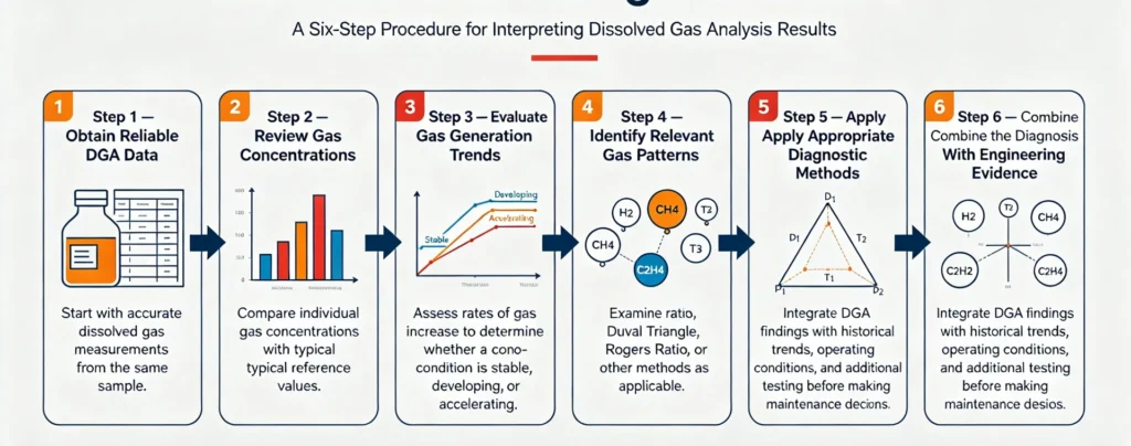
The IEC 60599 interpretation process can be summarized in six steps:
Step 1 — Obtain Reliable DGA Data
Start with accurate dissolved gas measurements from the same sample.
Step 2 — Review Gas Concentrations
Compare individual gas concentrations with typical reference values.
Step 3 — Evaluate Gas Generation Trends
Assess rates of gas increase to determine whether a condition is stable, developing, or accelerating.
Step 4 — Identify Relevant Gas Patterns
Examine gas combinations and relative proportions for diagnostic clues.
Step 5 — Apply Appropriate Diagnostic Methods
Use gas ratios, Duval Triangle, Rogers Ratio, or other methods as applicable.
Step 6 — Combine the Diagnosis With Engineering Evidence
Integrate DGA findings with historical trends, operating conditions, and additional testing before making maintenance decisions.
Frequently Asked Questions About IEC 60599 DGA
What is IEC 60599 used for?
It is the global standard for interpreting dissolved gas analysis data of oil-immersed electrical equipment, used for transformer fault classification, condition evaluation and maintenance guidance.
What gases are analyzed under IEC 60599?
Seven core gases: H₂, CH₄, C₂H₆, C₂H₄, C₂H₂, CO, CO₂, covering all characteristic gases of transformer electrical and thermal faults.
How does IEC 60599 interpret DGA results?
It adopts multi-dimensional comprehensive judgment of gas pattern matching, ratio analysis, concentration threshold and historical trend, rather than single data judgment.
What transformer faults can DGA detect?
It can detect partial discharge, low/high-energy discharge, and thermal faults of different temperature grades, covering most internal insulation faults of transformers.
Is IEC 60599 the same as IEEE C57.104?
No. IEC 60599 is an international standard focusing on fault pattern interpretation, while IEEE C57.104 is an American standard focusing on gas limit grading and risk classification.
Does IEC 60599 use the Duval Triangle?
The standard does not directly define the Duval Triangle, but recognizes graphical diagnostic methods as effective auxiliary verification tools for standard diagnosis.
Can DGA identify a transformer fault with certainty?
No. DGA is a predictive monitoring tool. Final fault confirmation requires combination of electrical tests, visual inspection and other means.
How often should transformer DGA be performed?
Routine monitoring follows annual/quarterly cycles; intensive monitoring is required for abnormal trends and post-fault scenarios.
Conclusion
IEC 60599 DGA provides unified, standardized and repeatable technical specifications for global transformer DGA interpretation and transformer fault diagnosis. Its core value is to convert discrete DGA test data into actionable equipment condition assessment results through pattern matching, ratio analysis and trend tracking.
In engineering practice, the combination of IEC 60599 standard specifications, Duval Triangle DGA graphical verification and online continuous monitoring can effectively avoid diagnostic errors, accurately identify latent faults and sudden abnormalities, and support power asset full-life-cycle management.
For EPC projects, utility operation and maintenance and power plant equipment management, standardized IEC 60599 DGA diagnosis is the core guarantee for safe and stable operation of transformer equipment. If you need customized online DGA monitoring system solutions, laboratory DGA testing services or professional fault diagnosis technical support for your transformer fleet, contact our technical team for targeted scheme consultation.
Reference & Technical Sources
- IEC 60599:2022, Mineral oil-filled electrical equipment in service – Guidance on the interpretation of dissolved and free gases analysis
- IEC 60567:2011, Oil-filled electrical equipment – Sampling of gases and analysis of free and dissolved gases
- IEEE C57.104-2019, Guide for Interpretation of Gases Generated in Mineral Oil-Immersed Transformers
- CIGRE Working Group 13.09, Transformer Diagnostics Monitoring Techniques
- Industry engineering specification: Field Application Guidelines for Transformer DGA Fault Diagnosis
[…] What Is IEC 60599? […]