

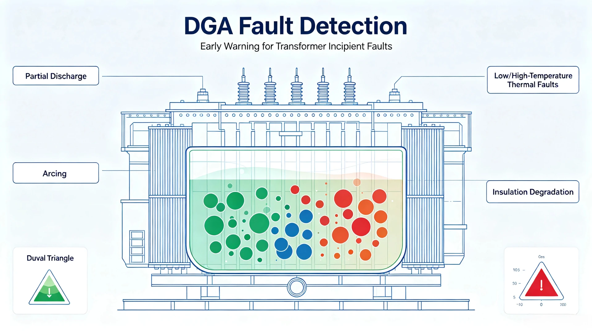
DGA fault detection uses dissolved gas concentrations, gas generation trends, and changes in gas composition to identify developing faults inside oil-filled transformers.
Rather than simply indicating whether a fault exists at the moment of measurement, DGA fault detection focuses on detecting developing faults. By combining gas concentration, rate of change, gas pattern, and historical trend, transformer fault detection using DGA helps determine whether a transformer is entering an abnormal condition. When abnormal gas behavior is detected, alarms, SCADA integration, and condition monitoring support further investigation and timely maintenance decisions.
How Does DGA Detect Transformer Faults?
DGA fault detection is a structured process that combines multiple layers of gas data rather than relying on a single reading.
| Step | DGA Data | Purpose |
|---|---|---|
| 1 | Gas concentration | Identify abnormal gas levels |
| 2 | Gas generation rate | Detect accelerating activity |
| 3 | Gas composition | Identify possible fault patterns |
| 4 | Historical trends | Detect developing conditions |
| 5 | Diagnostic methods | Classify the suspected fault |
| 6 | Alarm thresholds | Trigger engineering attention |
| 7 | Condition monitoring | Support follow-up inspection |
DGA fault detection is therefore not based on a single gas reading. Engineers normally evaluate gas levels, gas generation rates, gas relationships, and historical trends together. This layered approach supports transformer fault detection using DGA by identifying abnormal gas generation before it develops into a severe fault.
For the meaning of individual gases, see What Do DGA Gases Mean?
What Transformer Faults Can DGA Monitoring Detect?
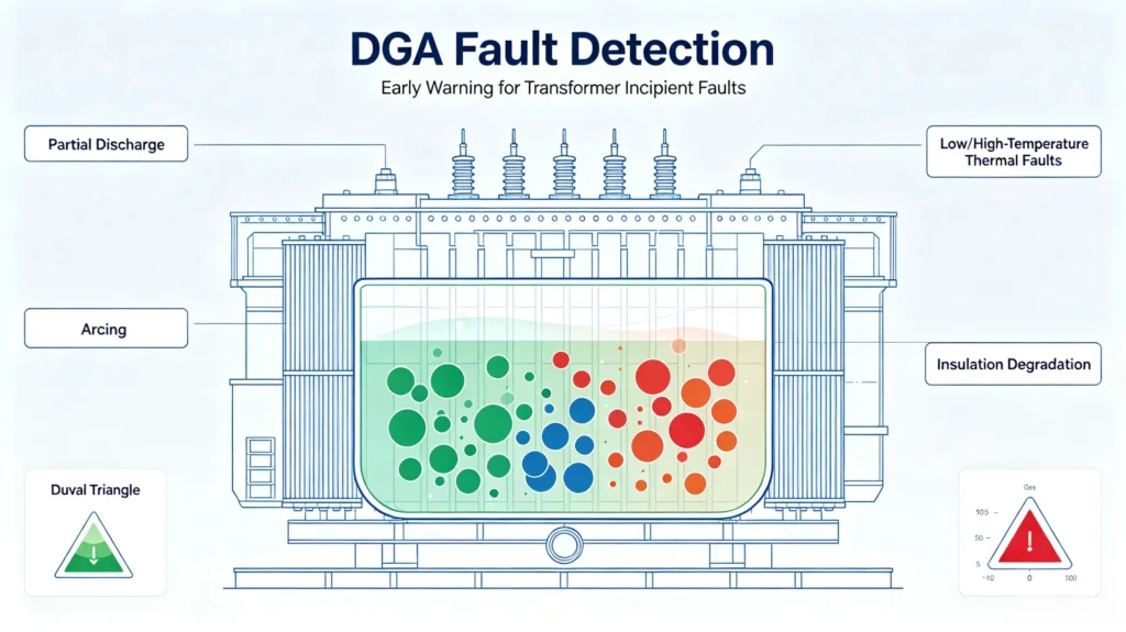
DGA identifies internal transformer faults by analyzing dissolved gas signatures in insulating oil. No single gas can fully confirm a fault type. Professional DGA fault diagnosis relies on integrated judgment of gas composition pattern, absolute concentration, rate of concentration increase, and real-time operating conditions. The table below summarizes common detectable faults, typical gas indicators and practical engineering implications, complying with IEC 60599 and IEEE C57.104 industry standards.
| Transformer Fault | Typical DGA Indicators | What the Pattern May Indicate |
|---|---|---|
| Partial discharge | H₂, sometimes trace CH₄ | Low-energy, continuous electrical discharge activity inside oil or insulation; typical early-stage electrical fault |
| Low-temperature thermal fault | CH₄, C₂H₆ | Local oil overheating below 300°C; mild thermal stress with no obvious carbonization |
| High-temperature thermal fault | Rising C₂H₄ (with CH₄/C₂H₆) | Severe thermal stress above 300°C; local hot spots and oil carbonization risk |
| Arcing (high-energy discharge) | C₂H₂ + elevated H₂ | Intermittent or continuous high-energy electrical arcing; critical abnormal electrical fault |
| Cellulose insulation overheating & degradation | Sustained rising CO, CO₂ | Thermal aging or overheating of paper insulation; progressive insulation performance decline |
| Mixed/complex fault | Simultaneous increase of multiple fault gases | Superimposed electrical and thermal stress; advanced developing internal fault |
How Is DGA Used for Transformer Fault Diagnosis?
DGA fault diagnosis combines several layers of analysis to determine whether a transformer is developing an internal fault. Rather than relying on a single gas value, it evaluates gas concentration, generation rate, composition, historical trends, and diagnostic methods together.
Gas Concentration
Gas concentration tells engineers how much gas is present in the oil. It provides the first indication of whether gas levels are within normal limits or have exceeded applicable thresholds. However, concentration alone cannot confirm a fault — a value within limits does not necessarily mean the transformer is healthy, and an elevated value does not always indicate an active fault.
Gas Generation Rate
Gas generation rate is a critical part of transformer fault diagnosis because absolute concentration does not equal a developing fault. A transformer with a relatively moderate gas concentration but a rapidly increasing generation rate may require more attention than a transformer with a higher but stable historical value. Rate-of-rise analysis often provides earlier warning than concentration thresholds alone.
Gas Composition
Different combinations of dissolved gases can provide clues about the type of abnormal activity. For example, the presence of acetylene alongside hydrogen suggests a different condition from elevated methane and ethane. Gas composition helps narrow down the possible fault direction without repeating the full gas-by-gas explanation covered in What Do DGA Gases Mean?
Historical Gas Trends
Historical trends compare previous DGA results with current measurements, evaluating:
- Rate of change
- Repeated abnormality
- Accelerating trend
This layer distinguishes between normal aging, transient fluctuations, and a developing fault. For a complete step-by-step interpretation process, see DGA Results Interpretation.
Diagnostic Methods
Diagnostic methods such as IEC 60599, the Duval Triangle, Rogers Ratio, and Key Gas Method can be used to interpret gas patterns after an abnormal condition has been identified. These methods classify the suspected fault type and support consistent, repeatable diagnosis. Detailed calculation examples are covered in DGA Results Interpretation.
Why Is Gas Trend Monitoring Important for Fault Detection?
Gas trend monitoring is essential because a single DGA measurement only tells you what the gas condition is at that moment. It cannot reveal whether a condition is stable, developing, or accelerating. That requires comparing current results with previous measurements over time.
| DGA Observation | Possible Interpretation |
|---|---|
| Stable gas level | No significant recent change |
| Gradual increase | Developing abnormal condition may require monitoring |
| Rapid increase | Potentially active fault condition |
| Repeated abnormal trend | Further diagnosis may be required |
These interpretations are indicative only. A rapid gas increase does not by itself confirm a transformer fault — it indicates a need for further investigation. Trend monitoring helps engineers distinguish between normal aging, transient fluctuations, and a developing condition that warrants closer attention.
For transformer fault detection using DGA, trend data often provides earlier warning than concentration thresholds alone. A moderate gas level that is rising steadily may be more significant than a higher level that has remained stable for years. This is why continuous or regular trend monitoring is a core part of DGA fault detection.
Rapid Gas Changes and Early Fault Detection
Early fault detection depends on recognizing changes in gas behavior before they develop into a serious condition. DGA monitoring does not wait for gas concentrations to reach high levels — it looks for the earliest signs of abnormal gas generation and tracks how those signs evolve.
The typical progression from normal operation to corrective action follows this sequence:
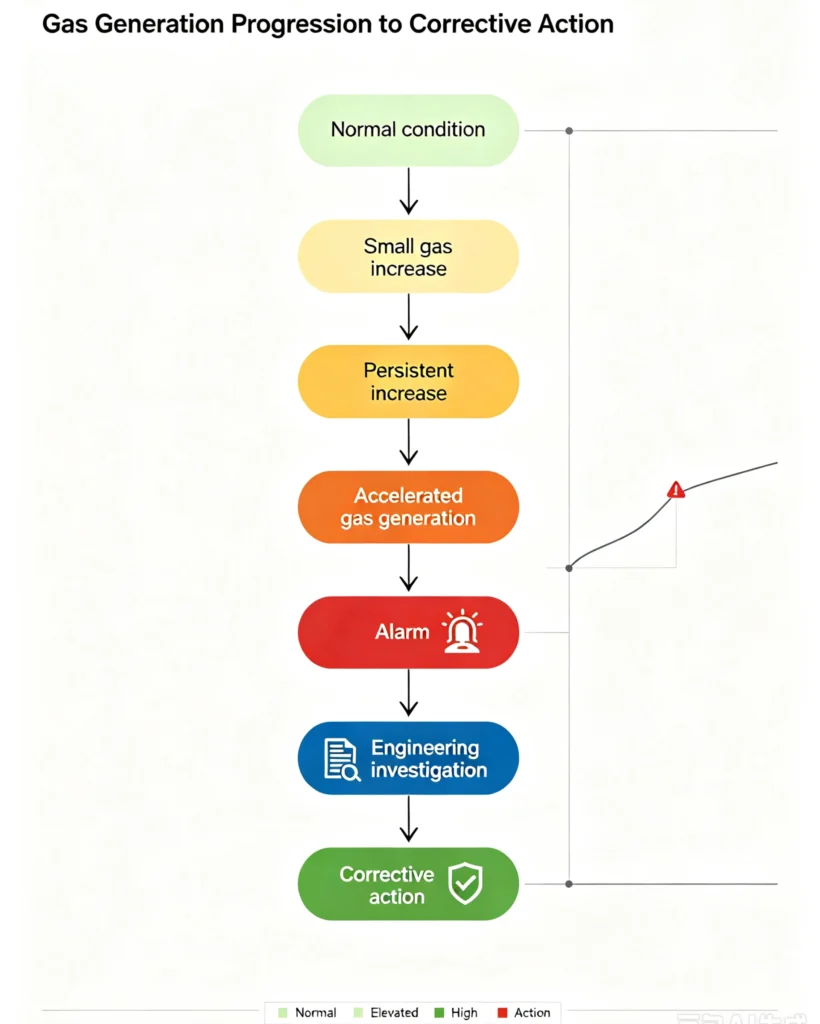
At each stage, the monitoring system provides different information. A small gas increase may only warrant attention. A persistent increase suggests a developing condition that should be monitored more closely. Accelerated gas generation typically triggers an alarm and prompts engineering investigation. Corrective action follows once the fault type and severity are confirmed.
This staged approach is what makes early fault detection possible. By catching abnormal gas behavior at the early stages, operators can investigate and respond before a developing fault causes severe transformer damage or unplanned outage. Rapid gas changes are particularly important because they may indicate an active fault condition — one that requires timely attention rather than routine follow-up.
DGA Alarm and Transformer Fault Detection
When DGA detects an abnormal condition, the monitoring system does not simply record a gas value — it triggers a response. Alarm logic is what converts gas data into actionable engineering attention.
Alarm Thresholds
DGA alarm thresholds are typically defined by a combination of:
- Gas concentration thresholds — based on applicable standards such as IEC 60599 or IEEE C57.104
- Rate-of-change thresholds — detecting rapid gas generation even when concentrations remain moderate
- User-defined limits — adjusted for transformer type, history, and operating conditions
- Equipment-specific alarm settings — configured for individual transformers or transformer groups
Because transformers differ in design, loading, and operating environment, alarm settings should be tailored rather than applied uniformly.
Alarm Levels
| Condition | Typical Response |
|---|---|
| Normal | Continue monitoring |
| Warning | Review trend and operating condition |
| Alarm | Perform engineering assessment |
| Rapid abnormal change | Investigate promptly |
A warning level typically indicates that gas behavior has deviated from baseline and should be reviewed. An alarm level indicates a more significant condition requiring engineering assessment. A rapid abnormal change — such as a sudden rise in acetylene — usually calls for prompt investigation, since it may indicate an active fault condition.
Alarm outputs can be delivered locally, pushed remotely, or transmitted to SCADA and centralized monitoring platforms, ensuring the right people are notified in time to act.
Online DGA Monitoring for Transformer Condition Monitoring
Online DGA monitoring supports transformer condition monitoring by providing continuous or frequent gas data rather than relying solely on periodic laboratory testing. It helps identify changes that may occur between scheduled laboratory tests — changes that could otherwise go unnoticed until the next sampling interval.
Periodic Laboratory DGA
Periodic laboratory DGA testing provides a snapshot at the time of sampling. It is useful for routine condition assessment, but it cannot capture gas behavior between test intervals. A developing fault may begin and progress during that gap without being detected.
Continuous Online DGA Monitoring
Online DGA monitoring provides continuous or frequent measurement, enabling earlier trend detection. It tracks gas concentrations, generation rates, and composition changes over time, supporting DGA monitoring for transformer faults as they develop.
What Online DGA Adds
- Continuous condition monitoring — ongoing visibility into transformer gas behavior
- Earlier trend detection — identifying changes between scheduled laboratory tests
- Alarm and notification — triggering timely engineering attention
- Remote monitoring — supporting centralized management and unattended substations
Online DGA monitoring does not replace laboratory testing, but it extends condition monitoring beyond the limits of periodic sampling. Together, they provide a more complete picture of transformer condition.
DGA Fault Detection vs Transformer Failure Detection
DGA is a powerful tool, but it is important to distinguish between fault detection and failure detection. These terms are related but not interchangeable.
| Term | Meaning |
|---|---|
| Fault Detection | Identifying evidence of an abnormal internal condition |
| Fault Diagnosis | Determining the likely fault type |
| Condition Monitoring | Continuously tracking transformer condition |
| Failure Detection | Identifying an actual or imminent loss of normal operation |
DGA fault detection is primarily concerned with identifying abnormal conditions — such as abnormal gas generation, rising gas trends, or unusual gas composition — that may indicate a developing fault. It is well suited to detecting developing abnormal conditions at an early stage.
Transformer failure detection, by contrast, involves identifying an actual or imminent loss of normal operation. This may require additional information beyond DGA, such as electrical test results, temperature data, partial discharge measurements, and operating records.
DGA is therefore best understood as a fault detection and condition-monitoring method, not a stand-alone failure prediction tool. It provides early warning and supports engineering assessment, but it should be combined with other diagnostic information when evaluating transformer condition.
What Should Engineers Do After DGA Detects an Abnormality?
When DGA detects an abnormality, the next steps should follow a structured engineering process rather than an immediate conclusion. The following six steps provide a practical response framework.
Step 1 — Verify the DGA Result
Confirm measurement quality and system status before acting on the result:
- Measurement quality
- Sampling or measurement conditions
- Sensor and system status
This step helps rule out false readings caused by sensor drift, sampling issues, or communication errors.
Step 2 — Compare Historical Data
Review previous measurements to place the current result in context:
- Previous DGA measurements
- Gas trend over time
- Rate of gas generation
A single elevated value may be less significant than a moderate value that is rising steadily.
Step 3 — Review Operating Conditions
Check whether operating factors may explain the abnormal reading:
- Load level
- Temperature
- Recent switching events
- Maintenance activities
- Abnormal operating events
Step 4 — Perform Fault Diagnosis
Apply diagnostic methods as needed:
- IEC 60599
- Duval Triangle
- Rogers Ratio
- Other diagnostic methods
These methods help classify the suspected fault type and guide further action.
Step 5 — Perform Additional Testing
Depending on the severity and diagnostic results, additional testing may be required:
- Laboratory DGA verification
- Electrical tests
- Insulation tests
- Visual or mechanical inspection
Step 6 — Decide Monitoring or Maintenance Action
Based on the overall assessment, determine the appropriate response:
- Continue monitoring
- Increase monitoring frequency
- Perform further testing
- Plan maintenance
- Schedule outage inspection
This structured approach ensures that DGA findings are translated into informed engineering decisions rather than reactive actions.
DGA Fault Detection Checklist
| Question | What to Check |
|---|---|
| Are gas concentrations abnormal? | Compare with applicable limits and historical data |
| Are gas levels increasing? | Check trend |
| Is the gas generation rate accelerating? | Compare measurement intervals |
| Are multiple gases changing? | Evaluate gas pattern |
| Is the change persistent? | Compare multiple measurements |
| Has the transformer operating condition changed? | Load, temperature, switching, etc. |
| Has an alarm been triggered? | Review alarm status |
| Is further diagnosis required? | Apply appropriate diagnostic methods |
| Is laboratory testing needed? | Confirm abnormal findings where appropriate |
Conclusion
DGA fault detection is based on monitoring dissolved gas concentrations, gas generation rates, gas patterns, and historical trends. By identifying abnormal or accelerating gas changes, DGA can provide early indications of developing transformer faults and support transformer condition monitoring. Transformer fault detection using DGA is most effective when gas data is interpreted together with diagnostic methods, operating conditions, and maintenance records — not as a stand-alone reading.
For utilities, asset managers, and EPC contractors, online DGA monitoring extends condition monitoring beyond periodic laboratory testing, providing continuous trend visibility and timely alarm notification. It helps reduce unplanned outage risks, optimize maintenance planning, and extend transformer service life.
Need help selecting the right DGA monitoring solution for your project? Share your transformer specifications, monitoring objectives, and communication requirements — our team will provide a tailored configuration and technical proposal.
FAQs About DGA Failure Detection
What faults can DGA detect in a transformer?
DGA can effectively detect developing partial discharge, high-energy arcing, low/high-temperature thermal overheating, and cellulose insulation degradation faults inside oil-immersed transformers, covering most common internal latent faults of power transformers.
Can DGA detect partial discharge?
Yes. Continuous rising H₂ and trace CH₄ are typical early characteristics of partial discharge faults. Combined with trend analysis, DGA can capture weak partial discharge activities that are difficult to find in routine inspections.
Can DGA detect thermal faults?
Yes. DGA achieves graded detection of thermal faults through thermal gas combinations: CH₄+C₂H₆ corresponds to low-temperature overheating, and rising C₂H₄ indicates severe high-temperature thermal stress and hot spot faults.
What gas indicates arcing in a transformer?
Acetylene (C₂H₂) is the core indicator gas for high-energy arcing faults. Any detectable or rapidly increased C₂H₂ concentration is a key warning signal of internal arcing discharge.
Can DGA detect insulation degradation?
Yes. Sustained abnormal growth of CO and CO₂ effectively reflects thermal degradation and accelerated aging of cellulose paper insulation, supporting long-term insulation health assessment.
Can DGA predict transformer failure?
DGA cannot achieve 100% failure prediction, but it can provide weeks to months of early warning for developing internal faults, helping operation teams eliminate hidden dangers before equipment failure and unplanned outage occurs.
Is online DGA monitoring better than laboratory DGA?
The two methods have their own advantages and are complementary. Online monitoring excels in continuous trend tracking and early warning, while laboratory testing is suitable for accurate calibration and in-depth fault analysis. Combined application achieves the best monitoring effect.
How often should transformer DGA be monitored?
Critical main transformers adopt 24/7 continuous online monitoring; conventional distribution transformers can adopt periodic laboratory sampling monitoring. For equipment with abnormal gas trends, increase monitoring frequency until the condition stabilizes.
Technical References & Data Sources
- IEC 60599:2022, Mineral oil-filled electrical equipment in service – Guidance on interpretation of dissolved and free gases analysis
- IEEE C57.104-2019, IEEE Guide for the Interpretation of Gases Generated in Oil-Immersed Transformers
- CIGRE TB 771: Transformer Condition Monitoring and Diagnostic Techniques
- Megger Official Technical Guidelines: IEC vs IEEE DGA Interpretation Standard Comparison (2025)
- Power Prognosis Industry Report: Complete DGA Standard Interpretation & Practical Limitation Analysis (2026)