

Author: Leon Zhang — Baoding Houfeng Trading Co., Ltd
Technical review: Power Testing Engineering Team — Senior Protection Engineer, 15 years in substation commissioning
Last updated: 21 October 2026
Current transformer simulation is the engineering practice of representing a current transformer by a mathematical model so that its ratio error, phase error and saturation behaviour can be predicted before the physical unit is energised. This guide shows plant and substation engineers how the model is built, what standards bound it, and how to use it for protection coordination and metering accuracy.
Key Takeaways
- A current transformer is modelled by an equivalent circuit whose nonlinear excitation branch decides where the core saturates.
- The knee point voltage, defined in IEC 61869-2:2012, is the single most useful number for predicting saturation under fault current.
- Protection classes (5P, 10P) are specified by composite error at an accuracy limit factor; metering classes (0.2S, 0.5S) are specified by ratio error across the load range.
- Simulation is done offline in network tools, in real time on hardware-in-the-loop rigs, or verified physically with a CT test set such as the HF-IT-203 current transformer calibrator.
- A simulation is only as good as the nameplate it starts from, so specify the datasheet evidence you require from a current transformer supplier before purchase.
What Is a Current Transformer
A current transformer is a type of instrument transformer that reproduces the primary current in its secondary winding at a fixed turns ratio, so that relays, meters and recorders can observe a high primary current through a safe, standardized secondary current that is normally 5 A or 1 A. Unlike a power transformer, a current transformer is deliberately designed to behave as a near-ideal current source over its working band.
A current transformer does three jobs at once. It scales the current down to an instrument-friendly value, it galvanically isolates the secondary from the high-voltage primary, and it constrains the secondary voltage so that the connected burden can be driven without saturating the core. The defining parameters are the rated transformation ratio (for example 600/5 A), the rated secondary current, the accuracy class, and the rated burden in volt-amperes.
Physically the most common constructions are the window (toroidal) type, where the primary is the conductor passing through the core; the wound primary type, used where a small number of primary turns is needed; the bushing type, built around an existing conductor; and the split-core or clamp type, which opens to be placed around a cable. For simulation purposes the construction matters only through its leakage reactance and the access it gives to the excitation characteristic.
For any engineer new to the topic, the phrase what is a current transformer is really a question about the equivalent circuit: a current transformer is only as linear as the excitation branch that shunts its secondary, and every simulation begins by describing that branch.
Why Simulate a Current Transformer
Current transformer simulation is the practice of representing a current transformer by an equivalent circuit so that its ratio error, phase error and saturation can be predicted before the physical unit is installed or fault-tested. Engineers simulate a current transformer for four reasons that directly affect plant reliability.
The first reason is protection coordination. A overcurrent or differential relay only sees what the current transformer delivers, so a simulation tells you whether the core will stay linear through the worst-case through-fault or will saturate and clip the current the relay needs. The second reason is metering accuracy: revenue and power-quality billing depend on the current transformer holding its ratio at low load as well as at full load, which a model makes explicit.
The third reason is specification. Before buying, you can simulate the candidate current transformer against the real burden and fault level to confirm that the chosen accuracy limit factor is adequate. The fourth reason is training and digital-twin work, where a simulated current transformer feeds a real-time protection relay so the relay logic can be exercised without a live substation.
Consider a 600/5 A protection current transformer feeding a relay across 200 m of 2.5 mm² cable. A quick simulation of the lead resistance shows the effective accuracy limit factor falls well below the nameplate, which is exactly the kind of surprise that a model surfaces before commissioning.
What Current Transformer Simulation Actually Models
The model every simulation tool uses is the single-phase equivalent circuit, in which the primary current divides into the transformed secondary current and the excitation current that flows through a nonlinear branch representing the magnetic core. The excitation branch is a nonlinear impedance whose value collapses as the core approaches saturation, and the secondary current that the instruments see is the ideal current minus that excitation current, which must also drive the burden impedance.
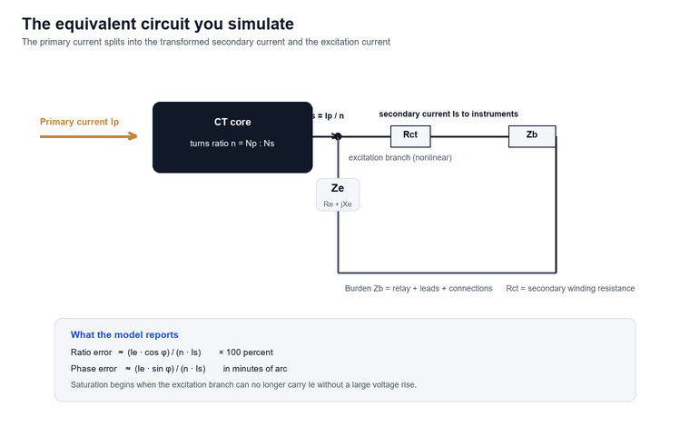
The two errors a simulation reports are derived directly from this circuit. The ratio error is approximately the excitation current multiplied by the cosine of the excitation angle, divided by the secondary current and the turns ratio, expressed as a percentage. The phase error is the same excitation current multiplied by the sine of that angle, expressed in minutes of arc. When the burden is resistive the ratio error dominates; when the burden is inductive the phase error grows. A model that ignores the burden power factor will therefore mis-state which error governs.
For a 600/5 A current transformer with a 0.5 Ω secondary winding resistance, a 10 VA burden at 0.8 power factor and an excitation current of 0.18 A at the operating point, the ratio error works out to about minus 1.8 percent and the phase error to about minus 34 minutes, both within a 5P class if the excitation current does not climb further.
The nonlinear part is the excitation characteristic, and that is why a simulation needs the nameplate excitation curve or, failing that, the rated knee-point voltage. Without the saturation data the model cannot tell you where the current waveform will distort.
Saturation and the Knee Point
The knee point voltage is the r.m.s. value of the sinusoidal voltage at rated frequency applied to the secondary terminals, all other windings being open-circuited, which, when increased by 10 percent, causes the r.m.s. value of the exciting current to increase by 50 percent. This definition, taken from IEC 61869-2:2012, gives a single, repeatable point on the excitation curve that separates the linear region from the saturated region.
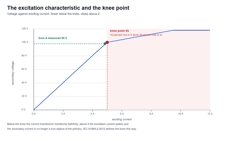
Below the knee the current transformer transforms almost perfectly. Above it the core cannot support more flux, the excitation current spikes, and the secondary current is no longer a faithful replica of the primary. For protection this is the failure mode that a simulation must predict, because a saturated current transformer hides the very fault current the relay exists to detect.
IEC 61869-2:2012 limits the composite error of a 5P protection class to 5% and a 10P class to 10% at the rated accuracy limit current and rated burden (IEC 61869-2:2012); both are measured at the rated burden and the rated accuracy limit factor. The composite error is the r.m.s. of the difference between the ideal and the actual secondary current over a specified cycle, so it captures both magnitude and phase distortion in a single figure.
The accuracy limit factor is the ratio of the rated accuracy limit primary current to the rated primary current, and it tells you how far the core stays linear above nameplate. Standard values are 5, 10, 15, 20 and 30. A 5P20 current transformer therefore holds a 5 percent composite error up to twenty times its rated primary current, which is the condition a through-fault imposes on a differential or overcurrent scheme.
The link between the knee point and the accuracy limit factor is the dimensioning equation. For a class P current transformer the rated knee-point e.m.f. must satisfy Ek ≥ ALF × (Rct + Rb) × Isn, where Rct is the secondary winding resistance, Rb is the total burden resistance and Isn is the rated secondary current. This single inequality is what the model checks first.
The knee point read on the excitation curve is not the same as the voltage at which the current transformer saturates under load. Under burden the saturation voltage follows the loop equation Vsat = iex·Rct + is·(Rct + Zb), so two 5P20 units with the same label but different Rct can saturate at very different fault currents even though their open-circuit knee points look close.
The table below shows how the effective accuracy limit factor collapses as the actual burden rises above the rated value, which is why a simulation must use the installed burden rather than the nameplate rating.
| Actual burden (% of rated) | Effective ALF | Composite error at rated ALF |
|---|---|---|
| 0 VA | ~50 | within 5 percent (5P) |
| 50 percent of rated current | ~15 | within 5 percent (5P) |
| 100 percent of rated current | 20 (nameplate) | within 5 percent (5P) |
| 150 percent of rated current | ~13 | rises above 5 percent |
| 200 percent of rated current | ~10 | exceeds 5 percent (fails 5P) |
Current Transformer Metering
Metering-class current transformers are governed by ratio and phase error across the load range rather than by composite error at high overcurrent, which means current transformer metering accuracy must be checked at one percent of load as carefully as at full load. The special classes 0.2S and 0.5S extend the accuracy down to 1 percent of rated current, which ordinary 0.2 and 0.5 classes do not guarantee, and that low-load accuracy is what makes revenue billing fair when a plant spends most of its life below peak demand.
For current transformer metering the burden sum decides the error, so the table below contrasts the metering and protection families on the single number each is judged by.
| Family | Classes | Judged by | Low-load accuracy | Typical burden |
|---|---|---|---|---|
| Metering | 0.2S, 0.5S, 0.2, 0.5 | Ratio and phase error across load | 0.5S holds ±1.5 percent at 1 percent of load | 2.5–5 VA |
| Protection | 5P, 10P, TPS/TPX/TPY/TPZ | Composite error at ALF | Not specified | 5–30 VA |
At 1 percent of rated current a 0.5 metering class may reach ±3% ratio error whereas 0.5S holds ±1.5% (IEC 61869-2:2012), a difference that grows into a visible billing discrepancy over a year of variable load. The 0.2S class tightens the limit further and is preferred where the connected demand exceeds about 100 kW and the meter is electronic with a low burden.
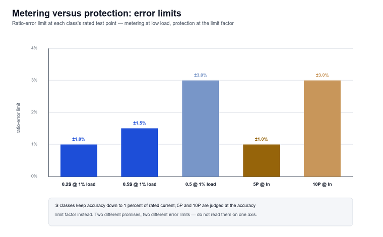
The instrument security factor, often written FS5 or FS10, is the metering counterpart to the protection accuracy limit factor. An FS5 current transformer is designed to saturate by five times rated primary current so that, during a fault, it never drives a dangerous multiple of rated secondary current into the connected meter. This protective saturation is intentional and is why a metering core should never be pressed into protection service.
The burden a metering current transformer sees is the sum of the meter impedance, the lead resistance and the connection resistance. Because the error grows with burden, a low-burden electronic meter is easier to keep accurate than an old moving-iron meter, and the model should always be re-run whenever the secondary wiring is changed.
Current Transformer Manufacturers and How to Specify One
Choosing between current transformer manufacturers is less about brand and more about the evidence each one can put on the datasheet, because a substation engineer ultimately buys a verified set of numbers rather than a logo on the nameplate. When you compare current transformer manufacturers, the datasheet evidence matters more than the marketing sheet, and the checklist below turns that evidence into a contract.
A substation engineer should request, at minimum, the rated transformation ratio, the accuracy class with its limit factor or security factor, the rated burden, the secondary winding resistance, and the excitation characteristic or rated knee-point e.m.f.
| Evidence to request | Why it matters | Minimum acceptable |
|---|---|---|
| Type test to IEC 61869-2:2012 | Confirms the design meets the standard | Test report number |
| Routine test per unit | Catches a bad unit before install | Certificate per serial |
| Excitation curve (digital) | Feeds the simulation directly | CSV or table |
| Knee-point e.m.f. and Rct | Sets the saturation margin | Single value each |
| Ratio and burden range | Matches the installed relay | Per nameplate |
A manufacturer that can show a type test to IEC 61869-2:2012 and a routine test report per unit is demonstrably in control of its process. Ask for the excitation curve in digital form so it can be loaded straight into your simulation, and confirm the ratio range the test set must cover if you intend to verify the delivery yourself.
For transparency, Baoding Houfeng Trading Co., Ltd. is a trading company and supplier, not a current transformer manufacturer. What we supply are the verification instruments that confirm a delivered current transformer meets its claimed ratings, such as the HF-IT-201 instrument transformer calibrator for error measurement and the HF-IT-203 current transformer calibrator for on-site ratio, burden and excitation testing. The HF-IT-207 CT burden tester and the HF-IT-210 instrument transformer analyzer complete a CT verification set.
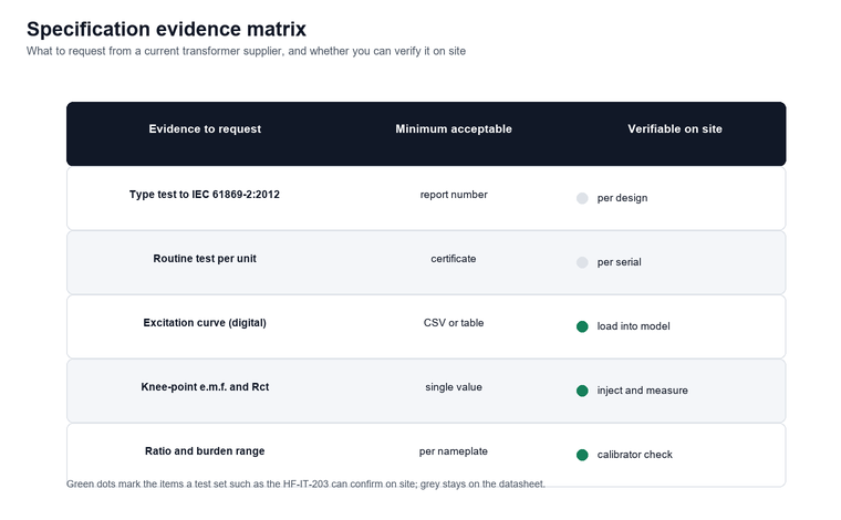
When you specify, write the requirement as a contract, not a hope. For a protection core state the class, the accuracy limit factor and the burden together (for example 5P20 10VA), and for a metering core state the class and the security factor (for example 0.5S FS5). The variable frequency instrument transformer tester is one way to confirm those numbers independently before the unit enters service.
Simulation Methods and Tools
There are three ways to study a current transformer, and the right one depends on whether you need a planning answer, a real-time answer, or a proof that the physical unit matches the model. Offline simulation uses network tools such as EMTP/ATP, PSCAD or ETAP, where the current transformer is one component in a larger fault or load-flow study and the excitation curve is entered as a lookup table.
Real-time simulation places the current transformer model, or the actual relay fed by a simulated current transformer, on a hardware-in-the-loop rig such as an RTDS or OPAL-RT cabinet. This is the method used to validate protection schemes because it reproduces the transient fault current, including the dc offset that drives the core toward saturation, in closed loop with the real relay.
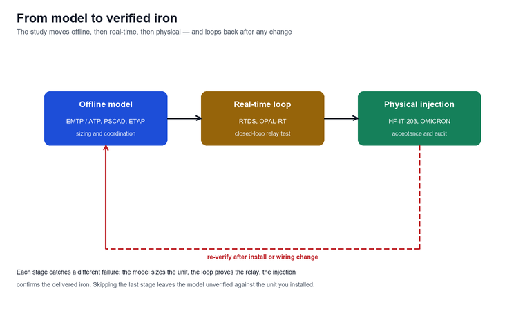
Physical verification is the third leg. A test set such as the HF-IT-203 injects current and measures the actual ratio error, phase error, excitation curve and knee point, so the simulation and the unit can be reconciled, and a wireless CT ratio tester removes the lead resistance from the measurement entirely. A digital substation adds a fourth layer, where the current transformer is represented by an IEC 61850-9-2LE sampled-value publisher and the relay subscribes to the stream.
The table below summarises the three stages and what the model reveals at each, so you can match the effort to the decision you need to make.
| Stage | Tool | What current transformer simulation reveals | When to use |
|---|---|---|---|
| Offline | EMTP/ATP, PSCAD, ETAP | Steady and fault behaviour, knee-point margin | Sizing and coordination |
| Real-time | RTDS, OPAL-RT | Closed-loop relay response to transients | Scheme validation |
| Physical | HF-IT-203, OMICRON, Doble | Actual error vs nameplate | Acceptance and audit |
For a plant engineer the practical sequence is: simulate offline to size the current transformer, model it in real time to prove the relay, then inject the delivered unit to confirm the nameplate. Each step catches a different failure, and skipping the last one leaves the model unverified against the iron you actually installed.
A Worked Simulation Example
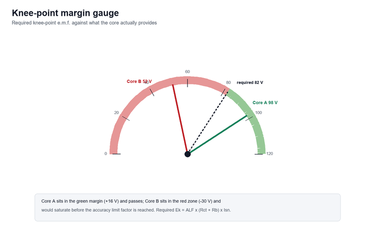
Consider a 600/5 A, 5P20, 10 VA protection current transformer with a secondary winding resistance Rct of 0.5 Ω, a rated secondary current Isn of 5 A, and a relay plus leads that present a 10 VA burden at 0.8 power factor, which is 0.32 Ω at 5 A. The required knee-point e.m.f. is Ek ≥ ALF × (Rct + Rb) × Isn = 20 × (0.5 + 0.32) × 5 = 82 V.
The table below computes the saturation margin for two candidate cores, one measured at a knee point of 98 V and one at 52 V, holding every other parameter constant.
| Candidate | Rct (Ω) | Rb (Ω) | Required Ek (V) | Measured Ek (V) | Margin | Verdict |
|---|---|---|---|---|---|---|
| Core A | 0.50 | 0.32 | 82 | 98 | +16 V | Pass |
| Core B | 0.50 | 0.32 | 82 | 52 | −30 V | Fail at high fault |
Core B, despite carrying the same 5P20 10VA label, would saturate before the accuracy limit factor is reached and would clip the fault current the relay depends on. This is exactly the kind of difference the model exposes before the unit is commissioned.
The worked example also shows why lead length matters. If the 200 m of 2.5 mm² cable raised Rb from 0.32 Ω to 0.52 Ω, the required knee point would climb to 20 × (0.5 + 0.52) × 5 = 102 V, and even Core A would fall short. Re-simulating after any wiring change is not optional.
Limitations and Boundaries
Every simulation is only as good as the nameplate it starts from, so the boundaries below should be stated explicitly whenever a result is used to accept or reject a protection or metering scheme.
In the field, two 5P20 units carrying the same label can show more than 40% difference in measured knee point when their secondary resistances differ, which is why a physical check of the delivered unit beats a paper comparison of nameplates (IEC 61869-2:2012).
- The equivalent circuit assumes a linear, known burden, but real leads, joints and relay inputs drift with temperature and age, so a field-measured burden should replace the nameplate estimate before the final check.
- Class P models ignore remanence and the detailed hysteresis loop, so they understate the risk when a previous fault has left a dc bias in the core; TPY and TPZ classes exist precisely because transient remanence matters.
- The excitation curve is normally supplied at one temperature, while the installed core runs warmer, lowering the knee point and shrinking the margin the simulation reported.
- Simulation software and its current transformer libraries carry their own licence and version assumptions; two tools can legitimately return different answers from the same nameplate if their saturation models differ.
FAQ
What is a current transformer used for?
A current transformer scales a high primary current down to a safe 5 A or 1 A secondary so that meters, protective relays and recorders can observe it without connecting directly to the high-voltage circuit. It also provides galvanic isolation between the primary conductor and the measuring equipment.
How do I calculate the knee point voltage of a CT?
Apply an increasing AC voltage to the secondary terminals with the primary open-circuited and record the exciting current at each step. The knee point is the voltage at which a further 10 percent rise causes the exciting current to rise by 50 percent, as defined in IEC 61869-2:2012. A test set such as the HF-IT-203 current transformer calibrator automates this curve.
What is the difference between 5P and 10P classes?
Both are protection classes defined by composite error at the accuracy limit factor, but 5P holds that error to 5 percent while 10P allows 10 percent. A 5P class also specifies a phase displacement at rated current, whereas 10P does not, making 5P the tighter choice for directional and differential protection.
Can I run current transformer simulation in ETAP or PSCAD?
Yes. Both ETAP and PSCAD, along with EMTP/ATP, let you enter the current transformer excitation characteristic as a curve and run fault or load-flow studies that show where the core saturates. For closed-loop relay validation you would move the model onto a real-time rig such as RTDS or OPAL-RT.
What burden should I assume for a 5P20 CT?
Assume the rated burden stated on the nameplate, for example 10 VA, but always re-calculate the actual burden from the relay impedance plus the lead resistance of the installed wiring. If the actual burden exceeds the rated value, the effective accuracy limit factor falls and the current transformer may saturate earlier than the nameplate suggests.
How often should a current transformer be tested?
New current transformers should be verified before commissioning, metering cores typically every one to three years, and protection cores annually together with the protective relays. Immediate re-testing is warranted after a through-fault, abnormal meter readings, or equipment overhaul. The HF-IT-203 current transformer calibrator supports this routine on site.
Does saturation affect metering or only protection?
Saturation affects both, but in different ways. A saturated metering core over-reads or under-reads the load current and distorts billing, which is why metering classes use a security factor to force early saturation. A saturated protection core clips the fault current and can delay or block relay operation, which is why protection classes are sized by the accuracy limit factor instead.
What standard covers current transformer accuracy?
The current international standard is IEC 61869-2:2012 for current transformers, with general requirements in IEC 61869-1:2007, and IEEE C57.13-2016 covers application in North American systems. Protection-specific transient classes are detailed in IEC 61869-2:2012 clause 5.4.
Conclusion
Current transformer simulation turns a nameplate into a behavioural model that predicts ratio error, phase error and, most importantly, saturation under fault current, which is the single behaviour that decides whether a protection relay sees the fault it was installed to clear. The knee point voltage from IEC 61869-2:2012 and the accuracy limit factor are the two numbers that decide whether a protection current transformer will deliver the fault current a relay needs, while the 0.2S and 0.5S classes decide whether a metering current transformer bills fairly at low load.
The model is only the first step. Confirm the delivered unit with the instrument transformer tester range, starting from the HF-IT-203 current transformer calibrator for ratio, burden and excitation testing, and the HF-IT-201 instrument transformer calibrator for laboratory-grade error measurement. If you need help matching a simulated current transformer to your real burden and fault level, contact us and our engineering team will run the dimensioning check with you.
References
- IEC 61869-2:2012, Instrument transformers — Part 2: Additional requirements for current transformers (webstore.iec.ch/publication/6065).
- IEC 61869-1:2007, Instrument transformers — Part 1: General requirements (webstore.iec.ch/publication/6047).
- IEEE C57.13-2016, IEEE Standard for Instrument Transformers (standards.ieee.org/ieee/C57.13/4867/).