

Tan delta testing is the field procedure that verifies a transformer’s insulation performance under power frequency excitation, reading the dielectric loss factor tan delta, the power factor and the dissipation factor test result so a rising loss factor, a capacitance drift or an insulation defect is found before the transformer is sent into service at full capacity.
This guide treats tan delta testing as a dielectric condition judgement procedure rather than a single loss reading. It covers how the tan delta and power factor are measured on the test lead and the measurement circuit, how the dissipation factor test result is read against the rated loss factor, and how the tan delta test procedure is repeated over the insulation life cycle before the transformer is energized.
Key Takeaways
- A tan delta reading only counts when it is compared against the rated loss factor, not against an absolute number, because a stable loss at a high value is normal for a short insulation while a rising loss shows a developing insulation defect.
- The dissipation factor test result must be read as a combination with the capacitance measurement, because the capacitance trend and the loss factor trend tell different parts of the insulation, and a loss rise with a stable capacitance points to a defect rather than a capacity drift.
- A tan delta test procedure run against a fixed test voltage and a fixed test frequency avoids different readings from the same insulation, because the loss factor depends on the test excitation, and a test that changes the excitation gives an inconsistent judgement.
- A tan delta test procedure without a boundary and a baseline comparison produces a loss number with no insulation life judgement attached to it, so the test result must be compared against the baseline before it is used for maintenance planning.
- A tan delta test procedure that omits the power factor channel leaves the real part of the impedance without a loss trend, so the power factor reading must be included so the tan delta result counts as the full dielectric picture.
tan delta measurement
The practice of tan delta measurement is the primary channel of a tan delta test procedure, because the dielectric loss factor reads the insulation continuity and the insulation state under power frequency excitation, and the reading is compared against the rated loss factor for the rated insulation. The measurement applies a known test voltage to the insulation and records the voltage, the current and the power factor, so the tan delta is computed and the reading is judged against the rated value and the insulation level.
A tan delta measurement matters most where the insulation continuity is suspect, because a degraded insulation or a loose or failing measurement lead will raise the measured tan delta and show up in the loss factor reading before any load or capacitance defect appears. A test that records only the voltage and not the current cannot compute the tan delta, so the current must be recorded alongside the voltage for the loss factor to be judged against the rated value.
tan delta measurement is the practice of measuring the dielectric loss factor on the primary and secondary test leads and comparing it against the rated loss factor for the rated insulation.
tan delta test procedure
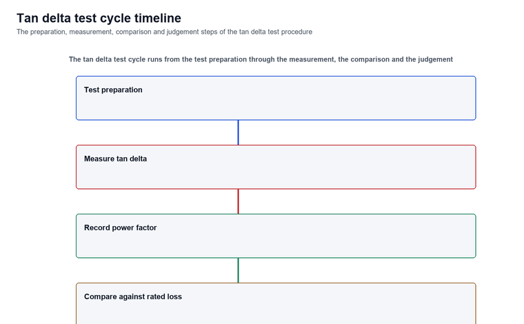
The practice of tan delta test procedure is the fixed sequence of a tan delta testing procedure, because the test carries the result that the dielectric loss and the capacitance behaviour are judged against. The procedure runs from the test preparation and the test excitation application, through the tan delta and power factor recording, to the comparison and the judgement against the rated loss factor.
The procedure applies the known test voltage to the test lead, records the primary and secondary tan delta, and records the power factor, so the tan delta is computed and the power factor is read against the impedance real part. A test that omits the power factor recording will leave the real part of the impedance judgement missing, and the loss defect that follows is not found before the transformer is energized.
tan delta test circuit wiring
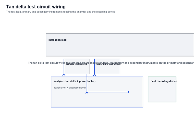
The practice of tan delta test circuit wiring is the channel that wires the test instrument, the measurement leads and the recording device so that the tan delta, the power factor and the dissipation factor test result are read in one pass, because the trend only counts when all three are measured under the same test conditions. The wiring places the test lead on the insulation lead, the primary instrument on the primary test lead, and the secondary instrument on the secondary test lead, all feeding the analyzer that computes the tan delta and records the power factor.
The circuit links the test instrument to the field recording device for the site, so the test result can be recorded and compared against the rated loss factor instead of a manual reading that needs a manual review. A local-only test box is a valuable box that nobody reads the result with.
dissipation factor test result bands
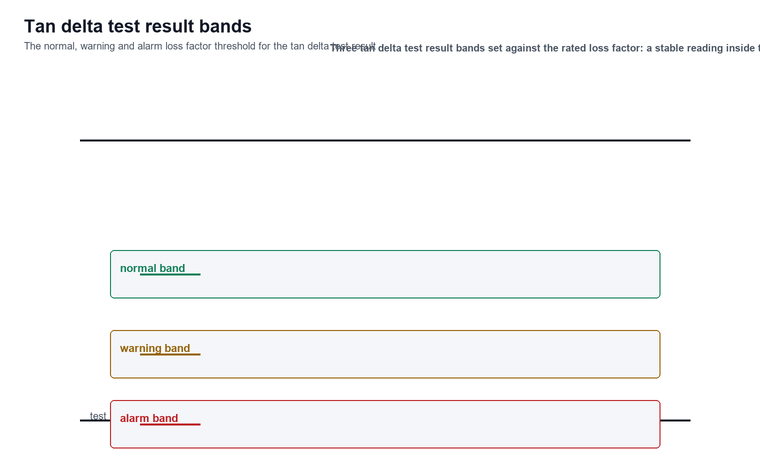
The test result is judged against a loss factor band rather than an absolute level. A loss that sits at a high but stable value for a year is not the same as a loss that has risen over the last test, even if the two end at the same number. The test uses three bands so the result is judged on the change rather than on a single reading, and the dissipation factor test result is read against the band for each insulation level rather than against the primary reading alone.
Test condition selection
The tan delta test condition selection decides the test voltage, the test frequency and the insulation level combination, because the loss factor depends on the test excitation and the measurement accuracy depends on the insulation level. The three factors are selected together so the reading can be judged against the rated loss factor with a stable and comparable result.
| Test factor | Value range | Unit | Applicable condition |
|---|---|---|---|
| Test voltage | 100–500 | V | Standard power frequency insulation test condition |
| Test frequency | 50 | Hz | Power frequency insulation test condition |
| Insulation level | Low / medium / high | Class | From low insulation maintenance to high insulation full-capacity service |
The test condition selection table sets the three core factors of the tan delta test: the test voltage, the test frequency and the insulation level, each with its value range, unit and applicable condition, so the test can be chosen to match the insulation maintenance stage and the rated loss factor judgement.
tan delta measurement layers
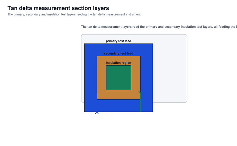
The tan delta measurement layers are the channel that reads the insulation primary and secondary loss layers feeding the test instrument, because the loss factor on the primary and the secondary test leads read different insulation regions, and the measurement layers feed the instrument that computes the tan delta and records the power factor.
power factor vs tan delta
The power factor versus tan delta relationship is the channel that separates the impedance real part from the insulation loss, because the power factor is the cosine of the impedance angle and the tan delta is the sine of that angle, so the power factor reading and the tan delta reading together show the impedance shape and the insulation loss shape. The test records both under the same test conditions, so the power factor change and the tan delta change are read against each other, and a power factor shift with a stable tan delta points to an impedance defect rather than an insulation loss defect.
The power factor versus tan delta relationship matters most where the transformer is used at a high load rating, because the impedance angle set by the core and the insulation sets the power factor floor, and a power factor change shows an impedance defect before the tan delta shows it. A test that records only the tan delta and not the power factor will miss the impedance defect, and the impedance that becomes unusable is not found before the transformer is energized.
How tan delta testing fits the insulation monitoring picture
The tan delta test procedure is the set that fits the insulation life picture between maintenance visits, and it answers a different question from a transformer condition monitoring system: what is the dielectric loss and the capacitance state under power frequency excitation, rather than whether the transformer passed a factory insulation test.
A tan delta test result only counts when the tan delta, the power factor and the dissipation factor test result are measured under the same test conditions and judged against the rated loss factor, because a stable high loss is different from a loss that has risen, and a stable power factor is different from a power factor that has fallen.
The test cycle runs from the test preparation, through the tan delta and power factor measurement, to the comparison and the judgement against the rated loss factor. A tan delta test result turns a scheduled insulation maintenance into a dielectric-based decision.
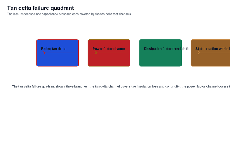
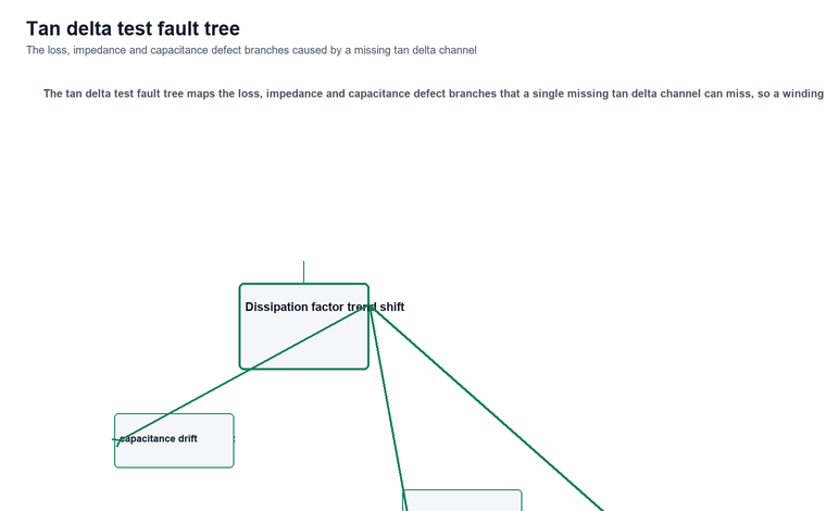
The test also distinguishes the failure modes the three channels catch. A tan delta above the normal band shows a rising insulation loss or a insulation continuity defect; a power factor change shows an impedance real part shift; and a dissipation factor test result trend change shows a capacitance or insulation state shift. The three together give a tan delta test report that tells the crew whether it is an insulation loss correction, an impedance check or a capacitance adjust.
Limitations and Boundaries
Three boundaries are worth stating before a tan delta test procedure is performed, and each limits what the loss reading can claim even when the test instrument is working and the numbers are clean.
First, the tan delta reading is affected by the test voltage and the test frequency, because the loss factor changes with the test excitation, so the reading must be judged against the rated loss factor at the rated test voltage and the expected test frequency, and not against a single absolute loss factor.
Second, the power factor is a screening signal rather than a measurement of the insulation defect itself, because the insulation and the test circuit configuration set the power factor floor, and the power factor is judged by the trend against the impedance rating rather than by a single isolated number. An online power factor reading is a trend built on the same physics, and it is not a substitute for the offline tan delta measurement.
Third, a test result only counts when the power factor is included for the impedance judgement. A tan delta test procedure installed without the power factor confirmation produces a loss number with no impedance judgement attached to it, and the result is not useful until the power factor reading is recorded alongside the loss factor.
FAQ
What three channels should a tan delta test procedure include?
A tan delta test procedure should include the tan delta, the power factor and the dissipation factor test result, because each channel answers a different question and together they show the dielectric loss, impedance and capacitance state of the insulation.
Why must the power factor be recorded alongside the tan delta?
The power factor must be recorded alongside the tan delta because the power factor sets the real part of the impedance for the transformer, and a power factor change shows an impedance defect before the tan delta shows it, so the impedance is confirmed before the loss factor is judged as a fault.
Can the tan delta measurement alone confirm an insulation loss defect?
The tan delta measurement is a screening number rather than a final judgement. It catches a rising insulation loss by showing a loss change, but it is not the full test because the power factor and the dissipation factor test result must be included to confirm the impedance and the capacitance behaviour, so the test result must be judged as the combination of all three channels.
Does the dissipation factor test result trend affect the insulation life?
The dissipation factor test result trend matters for the insulation life, because the loss factor sets the insulation dissipation and the capacitance state, so a dissipation factor test result change at the insulation level shows an insulation defect that affects the life and the behaviour. A test that reads only the primary insulation and not the secondary test leads will miss the insulation defect that affects the life.
Can the tan delta test procedure be done without a field recording device?
The tan delta and power factor must still be measured and recorded for the test to be judged, and the test result is compared against the rated loss factor by the field engineer. A test without a field recording device can still measure the three channels, but the result cannot be compared against the rated loss factor without a manual review of the recorded readings.
Conclusion
tan delta testing turns a scheduled insulation maintenance into a dielectric-based decision, and its value comes from how the tan delta, the power factor and the dissipation factor test result are measured and judged against the rated loss factor between maintenance visits. Follow the tan delta test procedure, measure the tan delta, the power factor and the dissipation factor test result under the same test conditions, and judge the result as the combination of all three channels against the rated loss factor rather than an absolute number. A stable high loss is not the same as a loss that has risen, and the power factor is the signal that confirms the impedance before the insulation defect degrades the transformer.
Last updated: 31 October 2026
References
- IEC 60050-1:2002, power frequency insulation tests and dielectric loss measurement standard
- IEC 60270:2025, partial discharge charge-based measurement standard
- IEC 60060-1:2010, switchgear general requirements and product standard reference
- IEC 60815-10:2016, capacitive measurement standard for dielectric measurements