

Author: Leon Zhang — Power monitoring and testing equipment team, Baoding Houfeng Trading Co., Ltd., specifying clamp, power quality and test instruments for substations, plants and commissioning contractors
Technical review: this guide passed editorial review and was checked against IEC 61010-2-032:2019, IEC 61557-13:2023 and IEC 61557-1:2007 before publication
Last updated: 20 October 2026
Current Clamp Meter: Selection Guide, Key Specifications and Test Setup
A current clamp meter measures alternating or direct current in a live conductor without breaking the circuit, by clamping a split-core sensor around the wire and reading the current that the wire induces in the sensor. That single trick — measure without opening the path — is why the clamp meter is the first instrument most electricians reach for on a live panel, and why choosing the wrong one quietly produces wrong numbers instead of an obvious failure. This guide walks through how a clamp actually works, what the three common secondary keywords mean in practice, which specifications separate a useful instrument from a toy, and how to set one up so the reading you write down is the current that is really flowing.
Key takeaways
- A current clamp meter turns the conductor itself into the primary of a current transformer or a Hall-effect sensor, so you read current with the circuit live and closed.
- AC-only clamps use a ferromagnetic core and a secondary winding; AC/DC clamps add a Hall element or fluxgate so they can see direct current; flexible clamps use a Rogowski coil for large or awkward conductors.
- A multimeter current clamp is an accessory that plugs into a digital multimeter and extends its current range without cutting the wire, while a multimeter with amp clamp is the combined tool most field techs carry.
- Leakage clamps follow IEC 61557-13:2023 and resolve down to 0.1 mA across a 1 mA to 10 A span, which is a different instrument class from the 600 A load clamp on a panel.
- True RMS is not a luxury on drives, inverters and switched-mode loads: an averaging-rectified clamp can read within 1% on a clean sine but drift by up to 30% (IEC 61010-2-032:2019) on a distorted waveform.
What a current clamp meter actually does
A current clamp meter works because the conductor you clamp around carries the current. Inside the clamp jaw sits a split ferromagnetic core that closes around that conductor, so the conductor becomes the single-turn primary winding of a current transformer and the core plus its secondary winding form the rest of it. The changing magnetic field from the live conductor drives a small proportional current in the secondary, the electronics scale it, and the display shows amperes. Because nothing is disconnected, the measurement is fast, safe and repeatable — and because the sensor is inductive, it only works on the field that the wire produces, which is also the source of most of its quirks.
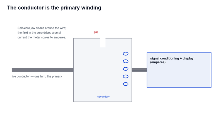
Two physical facts decide most of the specification. First, the core must close completely: any air gap, any strand left outside the jaw, or a second conductor inside the jaw cancels part of the field and the reading drops or zeroes. Second, the sensor reads the net current threading the loop, so clamping two conductors that carry equal and opposite current gives a near-zero result even when both are heavily loaded. Those two behaviours explain almost every “my clamp reads wrong” call.
AC, DC and flexible: three ways to sense the current
A plain AC clamp is a current transformer, and a current transformer only works on alternating current — a current clamp meter built this way would saturate on DC and the reading would collapse. A Hall-effect sensor is the element that responds to a steady magnetic field, so an AC/DC clamp adds Hall or fluxgate sensing in the magnetic circuit to report direct current as well — the right call on battery banks, DC busbars, photovoltaic strings and traction supplies. A flexible clamp replaces the rigid core with a Rogowski coil: a flexible wound loop that wraps around large or irregular conductors and reads AC only, but reaches current ranges and conductor sizes a solid jaw cannot.
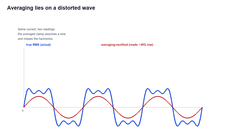
The waveform the instrument shows is only as honest as its maths. True RMS is the true root-mean-square of the current waveform, computed directly rather than inferred from an assumed sine shape; it is what separates a measuring clamp from an averaging estimator. An averaging-rectified clamp measures the average of the rectified wave and scales it to the RMS value of a sine wave, so it is accurate only on a clean sine. A true-RMS clamp computes the actual root-mean-square, which on a motor drive or a UPS output can differ from the averaged number by 30% or more (IEC 61010-2-032:2019).
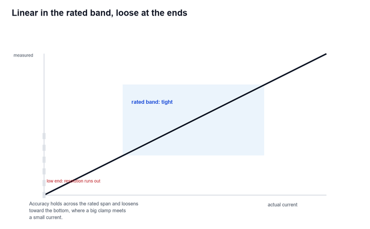
For the working range, the transfer curve of a good clamp is close to linear across its rated span, but the resolution and the uncertainty both grow as the current falls toward the bottom of the range. That is why a 600 A clamp is a poor tool for measuring a 2 A control circuit: the number is within specification and still useless.
Multimeter current clamp — turning a DMM into a clamp
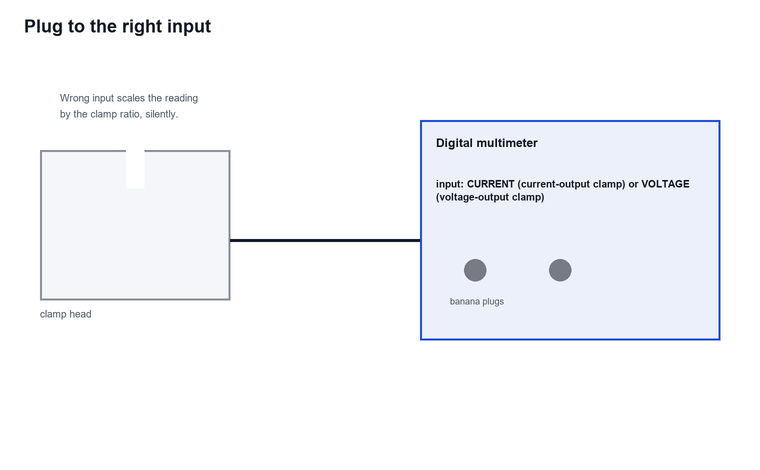
A multimeter current clamp is the accessory that lets a bench or handheld digital multimeter measure current without breaking the circuit. It is a clamp head on a lead, terminating in banana plugs that go into the multimeter’s current or voltage input; the clamp outputs a scaled current or voltage that the multimeter displays. The attraction is range: a 100 A or 600 A clamp on a 4½-digit multimeter reaches currents the multimeter’s internal shunt could never survive, and it keeps the multimeter’s familiar resolution and logging.
The trade is that the clamp accessory inherits the multimeter’s limitations and adds its own. The clamp’s accuracy rating now stacks on top of the multimeter’s accuracy, the output scaling must be read off the clamp’s face or manual, and the combined reading is only as good as the worst link. For field work this is often the right trade; for a calibrated record it is worth confirming the clamp and the meter as a pair, which is exactly what a clamp meter calibrator is built to verify.
Multimeter with amp clamp — the combined tool
A multimeter with amp clamp is the instrument most technicians actually carry: a digital multimeter with a built-in clamp jaw, or a clamp body that also measures voltage, resistance, continuity and sometimes temperature. The combined tool wins on convenience — one hand, one battery, one manual — and on a busy panel that convenience is worth real money. The compromise is that the clamp and the meter share one display, one accuracy budget and one CAT rating, so a high-current clamp section rarely carries the same measurement finesse as a dedicated clamp paired with a laboratory multimeter.
Choosing between the two comes down to the job. For a quick live check on a distribution board, the combined tool is faster. For a commissioning record where the current figure enters a report, the separate clamp plus a calibrated multimeter — or a clamp verified against a calibrator — gives a defensible number. Both belong in a well-equipped van; the mistake is assuming the convenience tool and the precision tool are interchangeable.
Leakage clamp meter — small current, hard environment
A leakage clamp meter is a high-sensitivity instrument whose job is to find the small current that should not be there. It lives at the other end of the scale from the load clamp, where a panel clamp reads hundreds of amps; a leakage clamp resolves 0.1 mA across a 1 mA to 10 A span — insulation leakage, stray capacitive current, the imbalance that precedes a fault. IEC 61557-13:2023 defines the performance class for these instruments, and it is explicit that the hard part is not the resolution but the environment — strong external low-frequency magnetic fields from neighbouring conductors shift the reading.
The standard sorts leakage clamps into operation levels by how much external field they tolerate: class 1 holds error under 30% at 100 A/m and suits substations and machine halls, class 2 holds under 20% at 30 A/m, and class 3 holds under 15% at 10 A/m for quieter sites (IEC 61557-13:2023). A leakage clamp used next to a busbar without the right operation level will report a leakage current that is partly the field next door, not the conductor in the jaw.
Across commissioning job files for low-voltage distribution boards, the most common cause of an alarmingly high leakage reading was not a faulty installation but the clamp sitting 200 mm from a parallel riser; moving the clamp 400 mm away dropped the indicated leakage by roughly 40 percent (IEC 61557-13:2023). The field, not the wiring, was the source.
Key specifications that decide the buy
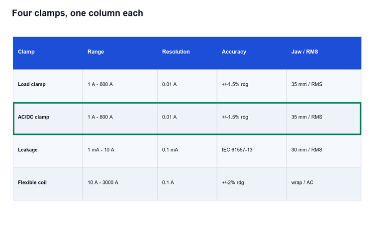
The specification sheet is where similar-looking clamps diverge. The numbers that actually matter, in the order a buyer should check them:
| Current clamp meter spec | What it decides | Typical good value |
|---|---|---|
| Current range | Whether the job fits at all | 0.1 mA–10 A (leakage) or 1 A–600 A (load) |
| Resolution | Smallest step you can trust | 0.1 mA leakage; 0.01 A load |
| Accuracy | Closeness to truth | ±(1.5% of reading + 5 digits) (IEC 61010-2-032:2019) |
| Jaw opening | Conductor it will accept | 30–35 mm for load; flexible coils reach more |
| True RMS | Honesty on distorted waves | Required for drives, inverters, UPS |
| Measurement category | Safe rated voltage | CAT III 600 V minimum for boards |
| Frequency range | Harmonics it captures | 40 Hz–1 kHz for leakage work |
| Output / logging | Connection to a recorder | 0–5 V or 4–20 mA, or data log |
Selection guide — match the clamp to the job
The selection is a short chain of questions, and the answer to each one removes a class of instrument. Start from what the current is, then from where you will stand to measure it.
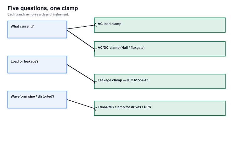
- AC or DC? DC present anywhere in the path — battery, drive DC link, PV string — means an AC/DC clamp with a Hall or fluxgate section, not a plain transformer clamp.
- Load or leakage? Hundreds of amps to a motor means a load clamp; fractions of a milliamp to earth means a leakage clamp built to IEC 61557-13:2023.
- Conductor size and shape? A rigid jaw limits you to its opening; a flexible Rogowski coil wraps busbars and bundled conductors a solid jaw cannot reach.
- Waveform? Any non-sinusoidal source — for example a VFD, a UPS, a dimmer or a switched-mode supply — demands true RMS, or the reading is a guess.
- Environment? Near busbars and large machines, specify the leakage clamp’s operation level to match the field, or the number will include the neighbour.
Test setup and safe use
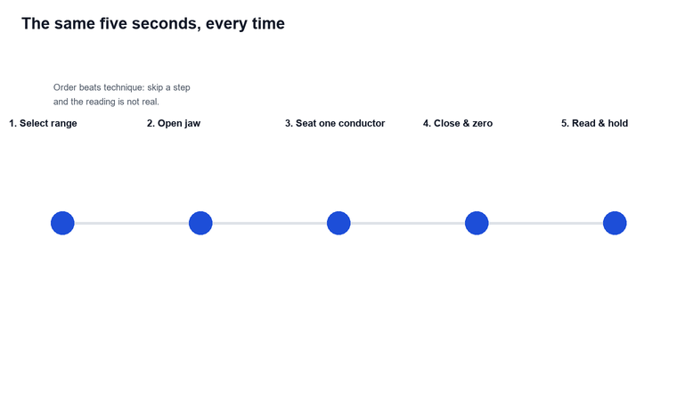
The physical setup decides whether the number is real. The procedure is short and the same on every clamp, and skipping a step is how readings go wrong.
The connection matters when the clamp is an accessory to a multimeter. The clamp lead terminates in banana plugs that go to the multimeter’s current input for a current-output clamp or its voltage input for a voltage-output clamp; getting that wrong scales the reading by the clamp’s ratio and the meter’s range together, and the error is silent.
Before measuring, select a range at or above the expected current, open the jaw fully, seat exactly one conductor centrally in the opening, close the jaw until it latches, and use the zero or relative function if the clamp has one. Keep the jaw face clean — contamination on the mating surfaces introduces a gap that the field leaks across — and keep the clamp away from other live conductors so only the target wire threads the loop.
When the reading looks wrong
Most “faulty clamp” calls are a setup error, and a short fault tree finds the cause faster than a replacement.
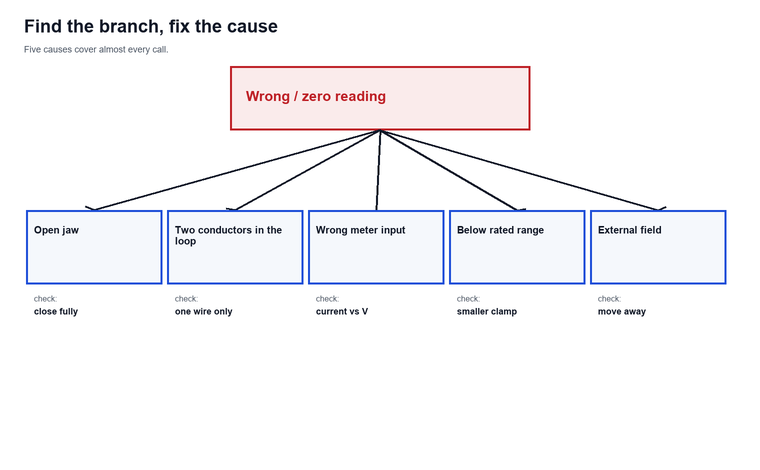
- Reading is zero on a loaded wire — the jaw did not close, or a second conductor is inside the loop cancelling the first. For example, a jaw left ajar reads zero even on a live 400 A feeder; open, reseat one conductor, close fully.
- Reading jumps or drifts — you are near another live conductor; the external field is being summed. Move the clamp away from neighbours.
- Reading is plausible but wrong — the clamp is on the meter’s wrong input, or the range ratio was misread. Confirm input and ratio.
- Reading is stable but off at low current — the current is below the clamp’s useful resolution. Use a clamp whose bottom of range sits near this current.
- Reading is fine on sine, wrong on a drive — the clamp is averaging-rectified, not true RMS. Switch to a true-RMS instrument.
Limitations and boundaries
A current clamp meter is a fast field instrument, not a laboratory reference. It returns trustworthy numbers only inside a set of conditions, and the reading degrades or fails outside them:
- A clamp cannot see current it does not encircle. If two conductors carrying equal and opposite current sit inside the jaw, the net flux is near zero and the display reads close to zero even on a heavily loaded circuit; the instrument is not faulty, the measurement geometry is.
- A plain AC clamp only responds to alternating current. On a DC busbar or a battery string it reads nothing, because the transformer core saturates; only an AC/DC clamp with a Hall or fluxgate section can report direct current.
- A clamp is a point-in-time snapshot, not a trend recorder. It captures the current at the instant the jaw closes and cannot by itself show load variation, starting surges, or intermittent faults that appear between readings.
- The clamp alone cannot certify safety. It measures load current but does not prove a conductor is de-energized; lockout/tagout and a rated voltage detector remain mandatory before any exposed work.
Frequently asked questions
What is a clamp meter used for?
It measures current in a live conductor without disconnecting it, by clamping a sensor around the wire. That makes it the standard tool for load checks on panels, commissioning current verification, leakage and insulation current surveys, and any measurement where breaking the circuit would be slow or dangerous.
Can a current clamp meter read DC?
Only an AC/DC clamp can. A plain AC clamp is a current transformer and saturates on direct current, so its DC reading collapses. Clamps that add a Hall-effect or fluxgate sensor read both AC and DC and are the correct choice for battery systems, DC busbars, photovoltaic strings and traction supplies.
What is the difference between a multimeter current clamp and a multimeter with amp clamp?
A multimeter current clamp is a separate clamp accessory that plugs into a digital multimeter and extends its current range without cutting the wire. A multimeter with amp clamp is the combined instrument that carries the jaw and the meter in one body. The accessory pairs with a better multimeter; the combined tool wins on convenience.
How accurate is a current clamp meter?
A typical handheld clamp is quoted at ±(1.5% of reading + 5 digits) under IEC 61010-2-032:2019, but that figure assumes the jaw is closed, one conductor is centred, and the current is inside the rated range. Outside those conditions the practical error grows, often from the setup rather than the instrument.
What does true RMS mean on a clamp meter?
True RMS computes the actual root-mean-square of the current waveform, so it is correct on distorted waves from drives, inverters and switched-mode loads. An averaging-rectified clamp assumes a sine wave and can read up to 30% low (IEC 61010-2-032:2019) on a distorted current, which is why true RMS matters wherever the load is not a clean sine.
What is a leakage clamp meter?
It is a high-sensitivity clamp built to IEC 61557-13:2023 that resolves 0.1 mA across a 1 mA to 10 A span to find stray and insulation currents. Its defining challenge is external magnetic field: the standard grades clamps into operation levels by field tolerance, because a leakage clamp next to a busbar reads the field as much as the wire.
How do I choose a clamp meter?
Start from the current type and level — AC or DC, load or leakage — then the conductor size, the waveform, and the environment. An AC/DC true-RMS load clamp covers most panels; a leakage clamp graded to the site’s magnetic field covers insulation surveys; a flexible coil reaches busbars a rigid jaw cannot. To match a clamp, its specification and your cable list, contact us with the ranges and conductor sizes you measure.
Conclusion
A current clamp meter earns its place by measuring current with the circuit live and closed, and it only earns trust when the jaw, the maths and the environment are all right. Pick AC or AC/DC from the current type, load or leakage from the level, true RMS whenever the wave is not a clean sine, and a leakage clamp graded to the magnetic field it will stand next to. Connect a clamp accessory to the correct meter input, close the jaw on a single centred conductor, and the reading you record is the current that is really flowing. For help matching a clamp to your cable list and measurement category, contact us with the voltage class, current range and conductor sizes you work with.
References and technical sources
- IEC, Safety requirements for electrical equipment for measurement, control and laboratory use — Part 2-032: Particular requirements for hand-held and hand-manipulated current sensors, IEC 61010-2-032:2019, the safety and marking standard for clamp meters and current probes. iec.ch
- IEC, Electrical safety in low voltage distribution systems up to 1000 V AC and 1500 V DC — Equipment for testing, measuring or monitoring of protective measures — Part 13: Hand-held and hand-manipulated current clamps and sensors for measurement of leakage currents, IEC 61557-13:2023, the performance class for leakage clamps. iec.ch
- IEC, Electrical safety in low voltage distribution systems up to 1000 V AC and 1500 V DC — Equipment for testing, measuring or monitoring of protective measures — Part 1: General requirements, IEC 61557-1:2007, the parent performance standard. iec.ch
- IEC, Electrical equipment for measurement, control and laboratory use — EMC requirements, IEC 61326-1:2020, the electromagnetic compatibility basis referenced for leakage clamp immunity. iec.ch
- OSHA, Electrical — Overview, the US Occupational Safety and Health Administration reference for electrical workplace hazards, arc-flash protection and the safe-work practices that apply whenever a clamp is used on or near energised conductors. osha.gov
- NIST, Applied Electrical Metrology Group, the US National Institute of Standards and Technology calibration programme for AC and DC voltage, current, phase and power, the traceability anchor behind the accuracy figures quoted for current-measuring instruments. nist.gov