

Author: Leon Zhang — Power monitoring and testing equipment team, Baoding Houfeng Trading Co., Ltd., specifying transformer test sets for substations, utilities and industrial plants
Technical review: this guide passed editorial review and was checked against IEC 61010-1:2010, IEC 61010-2-033:2023, IEC 61010-031:2022, IEC 61557-1:2019 and IEC 60529:2013 before publication
Last updated: 24 October 2026
Digital multimeter for electricians: Selection Guide, Key Specifications and Test Setup
A digital multimeter for electricians is judged less by how many digits it displays than by how it behaves on the third job of a wet Tuesday: the leads are damp, the panel is live, the reading has to be believed, and the CAT III 600 V rating printed beside the jacks is the only thing standing between a mistake and an arc flash. This guide works through what an electrician actually asks a meter to do, how to read a 7-function label without being misled by it, what the category and the transient rating on the front really promise, which parts of the hardware decide whether the meter survives its first year in a van, and how to set up the measurement so the number means what you think it means. It is written for the person choosing the meter and for the apprentice who has just been handed one and told to check a board before touching it.
Key Takeaways
- Four jobs decide everything else: proving a circuit dead, finding why it is not working, confirming it is inside tolerance, and surviving all three a dozen times a day — a digital handheld multimeter specified for anything else is specified for the wrong job.
- On a hand-held meter built to measure mains voltage, the current standard does not allow CAT II to be printed on the mains terminals at all: those terminals carry CAT III or CAT IV (IEC 61010-2-033:2023).
- The category letter and the working voltage have to be read together, because the transient test behind them is what does the work: CAT III 600 V is tested at 6 000 V from a 2 Ω source, while CAT II 1 000 V is tested at 6 000 V from a 12 Ω source (IEC 61010-1:2010).
- A 7-function digital multimeter label is a marketing count rather than a standard one, so the only reliable comparison is which seven functions are being counted and what each one actually measures.
- Accuracy is a formula, not a number: ±(0.5 percent + 2) means half a percent of the reading plus two counts of the least significant digit, and on a 4 000-count meter those two counts are worth roughly half a volt on the 100 V range.
- Most wrong readings are correct answers to the wrong question — ghost voltage, burden voltage, lead resistance and the wrong jack for the rotary position account for almost all of them.
What an Electrician Actually Asks a Meter to Do
A working electrician asks a meter to do four things, and only one of them is a measurement: prove a circuit dead, find out why it is not working, confirm it is working within tolerance, and survive doing all three a dozen times a day.
Each of those jobs pushes the specification sheet in a different direction. Proving a circuit dead puts the safety case first — category, transient rating, fuse energy and lead construction — and nobody cares whether the meter resolves a tenth of a volt. Finding a fault puts resolution and response first, because the difference between 0.4 Ω and 0.04 Ω across a contact decides whether a partner gets replaced. Confirming tolerance puts repeatability first, which is where accuracy formula and calibration interval start to matter. All four jobs sit against the same panel, usually within the same half hour.
The consequences of getting each one wrong are different too, which is worth stating plainly before any of the numbers:
| Job for a digital multimeter for electricians | What it really asks | Function doing the work | What goes wrong when the meter is not up to it |
|---|---|---|---|
| Prove dead | faith in a 0 V reading | voltage input, category rating | a high-impedance input shows coupled voltage and the circuit is declared live — or the reverse |
| Find the fault | the ability to see a small difference | millivolt and ohm resolution, continuity buzzer | a 0.5 Ω contact reads as zero and the search moves past it |
| Confirm tolerance | repeatability over months | basic accuracy, stability, calibration | two meters disagree and neither can be believed |
| Survive the day | mechanical and ingress integrity | case, holster, jacks, IP rating (IEC 60529:2013) | worn jacks make intermittent contact and every reading becomes suspect |
Notice that only one row is really about accuracy, which is not how multimeters are marketed.

What a 7-Function Digital Multimeter Label Actually Means
The number in front of “function” is a marketing figure rather than a standard one, so two meters labelled 7-function can be counting different things, and the only reliable way to read the label is to count what each position on the dial actually measures.
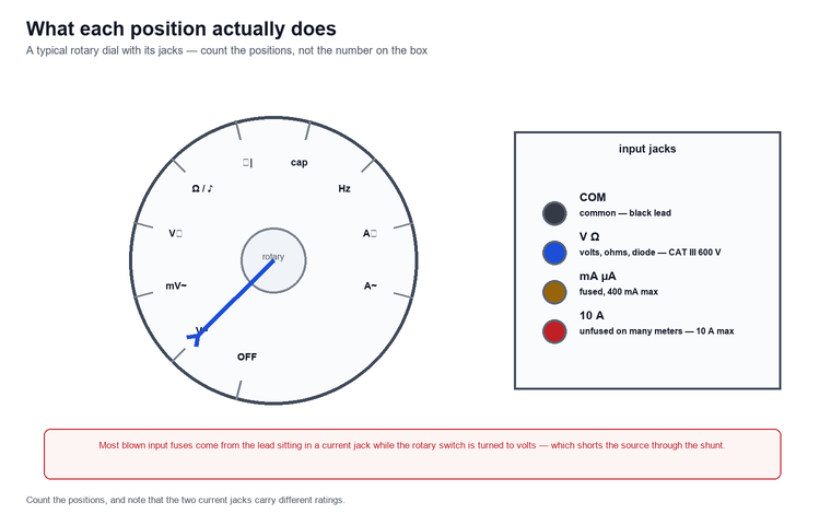
There is no definition of “seven functions” in the standard that governs these instruments (IEC 61010-2-033:2023), and manufacturers reach seven by different routes: some count continuity separately from resistance, some count diode test separately from continuity, some count capacitance and frequency and drop the current ranges that a general-purpose electrician uses weekly. Consider what that means in practice — a 7-function meter advertised without a current range is a voltage and continuity tester with a plausible-looking label, and it will not tell you that until you look at the rotary positions. The practical rule is to count the positions on the dial and ignore the number on the box:
| Function | What it returns | Where a 7-function label usually includes it | Site task it serves |
|---|---|---|---|
| AC / DC voltage | RMS or average-responding value between two points | always | proving dead, supply checks |
| AC / DC current | current in series, or via a clamp accessory | usually current-coded jacks | load check, circuit verification |
| Resistance | ohms, with the circuit isolated | always | continuity of a conductor, contact quality |
| Continuity | audible threshold below a stated resistance | sometimes counted separately | tracing a conductor quickly |
| Diode / transistor test | forward voltage drop of the junction | often counted | checking a rectifier or a driver output |
| Capacitance | capacitance with the circuit discharged | sometimes | motor run capacitors, filter banks |
| Frequency | fundamental frequency of the input | sometimes | drive output, generator checks |
Which of these a 7-function digital multimeter actually delivers is the first question to ask a supplier, because the answer changes what else you have to carry.
Digital Handheld Multimeter Safety: Category and Transient Rating
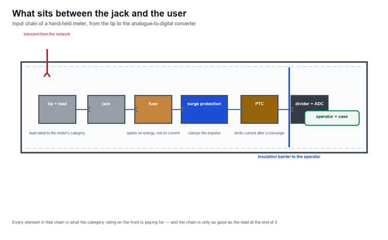
Every rating printed beside the input jacks has two halves, and the half most people read — the voltage number — is the less important one: the category letter tells you how much energy the meter has to absorb when the network throws a transient at it.
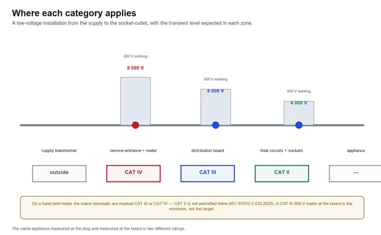
Measurement categories describe where in an installation a meter may be connected, and IEC 61010-1:2010 assigns each combination of category and working voltage an impulse-withstand level measured from a source with a defined impedance. The working numbers, at the voltages an electrician actually meets:
| Working voltage to earth | CAT II impulse | CAT III impulse | CAT IV impulse |
|---|---|---|---|
| 300 V | 2 500 V (12 Ω source) | 4 000 V (2 Ω source) | 6 000 V (2 Ω source) |
| 600 V | 4 000 V (12 Ω source) | 6 000 V (2 Ω source) | 8 000 V (2 Ω source) |
| 1 000 V | 6 000 V (12 Ω source) | 8 000 V (2 Ω source) | 12 000 V (2 Ω source) |
Two things follow from that table, and both are counter-intuitive (IEC 61010-1:2010). First, the same impulse voltage does not mean the same protection: CAT II 1 000 V and CAT III 600 V are both tested at 6 000 V, but the CAT III test uses a 2 Ω source against 12 Ω for CAT II, and a lower-impedance source delivers several times the current at the same voltage. Second, a meter must be rated for the worst category it can ever be plugged into, not the one it is used in most — a distribution board fed from a service entrance is CAT III work even if the panel looks like every other panel.
The standard governing hand-held multimeters goes further than recommending a category. Since IEC 61010-2-033:2023, terminals of measuring circuits rated for mains voltage are marked CAT III or CAT IV with the nominal line-to-neutral voltage, and marking them CAT II is not permitted (IEC 61010-2-033:2023); the third edition published on 20 September 2023 also added requirements for surge protective devices inside the meter and a new clause on protecting the measuring circuit against the spread of fire and arc flash. In other words: if the label says CAT II on the mains input, it is a compliance question before it is a suitability question.
On one pre-purchase check for a maintenance contractor, six meters were laid out on a bench with six apparently equivalent specification sheets, and two of them carried a CAT II marking on the input jacks at 600 V — a marking no current hand-held multimeter standard permits on mains terminals (IEC 61010-2-033:2023) — and the same two carried no category marking on their leads at all. The other four declared CAT III 600 V or CAT IV 600 V on the terminals and CAT III or CAT IV on the leads. Six meters at the same price, two that should not have been bought, and a thirty-second check that separates them.
The leads matter as much as the meter. Probe assemblies are covered by their own document — IEC 61010-031:2022, edition 3.0, published on 22 December 2022, which also introduced Kelvin probes as a probe type and, for the first time, probes intended to measure voltage without any electrical connection to the conductor (IEC 61010-031:2022). A CAT III 1 000 V meter on CAT II leads is a CAT II installation, and the paperwork that came with the instrument usually says so in small print.
For a sense of what a real compliance statement looks like, take an instrument in this family: the HF-GT-209 clamp ground resistance tester declares conformity with the three documents that govern this class — the general safety part, the probe standard and the installation-test-equipment part — at CAT III 300 V and CAT IV 150 V with pollution degree 2, and backs it with insulation resistance of at least 20 MΩ at 500 V between circuit and housing and a withstand test of AC 3 700 V RMS. That is what a printed rating is supposed to mean: a category, a working voltage, a pollution degree and the test evidence behind them.
Portable Digital Multimeter Build: What Survives the Van
A portable digital multimeter lives in a van under a coil of cable, gets pulled out into the rain and dropped once a week, and the specifications that decide whether it still works in six months are mostly mechanical rather than electrical.
Work backwards from the failure modes and the checklist writes itself. Ingress protection is rated under IEC 60529:2013, which defines the two-digit code for solids and liquids (IEC 60529:2013) — a second digit of 4 or higher is what separates “survives drizzle” from “survives being set down in a puddle”. Operating temperature and humidity ranges are printed against a narrower band than most people assume: purpose-built field instruments in this class are typically quoted at −10 °C to 40 °C and no more than 80 percent relative humidity, and accuracy is usually guaranteed inside an even narrower reference band of 23 °C ± 5 °C. Display readability in a switchroom is a specification too, not a preference, and battery life decides whether the meter is switched on when the fault finally shows up.
| Check | What to look for | Why it fails on site |
|---|---|---|
| Ingress | IP code to IEC 60529:2013, second digit 4 or better | damp boards, outdoor boards, condensation in a cold van |
| Input jacks | shuttered jacks, tight fit after a year | worn jacks make intermittent contact and every reading becomes suspect |
| Fuse access | replaceable without opening the case further than the battery door | wrongly fused meters are not repaired, they are thrown away |
| Drop and holster | stated drop height, holster that survives it | leads wrench sideways out of the case in a fall |
| Display size | readable at arm’s length, backlight | dim displays get misread in a shaded board |
| Battery life | stated hours of continuous use | auto power-off of 15 minutes is a compromise, not a feature |
Two details from this family of instruments are worth holding up as benchmarks, because they show what “specified for site” looks like in practice. The HF-GT-209 clamp ground resistance tester is quoted for 0.01 Ω resistance resolution and 0.001 mA current resolution on a 2.4-inch colour screen of 46 mm by 29 mm, weighing 975 g with the battery fitted, running more than eight hours on its 3.7 V lithium pack and switching itself off 15 minutes after the last operation. The HF-LT-308 digital insulation resistance meter takes the other end of the trade-off — a single-hand tool of 185 mm by 83 mm by 30 mm and roughly 300 g, running on four AA cells, rated to ±5 percent basic error over a 0 to 1 999 MΩ range with 1 MΩ resolution, and usable from −10 °C to +50 °C.
Choosing a Digital Multimeter for Electricians: Reading the Specification Sheet
A specification sheet is a negotiation between what the instrument does and how honestly the manufacturer is willing to state it, and the two lines that matter most — the accuracy formula and the input impedance — are the two most often printed without their conditions: the headline figure is quoted between 18 °C and 28 °C, below 75 percent relative humidity, for a stated period after calibration, and none of those conditions is met on a roof in February.
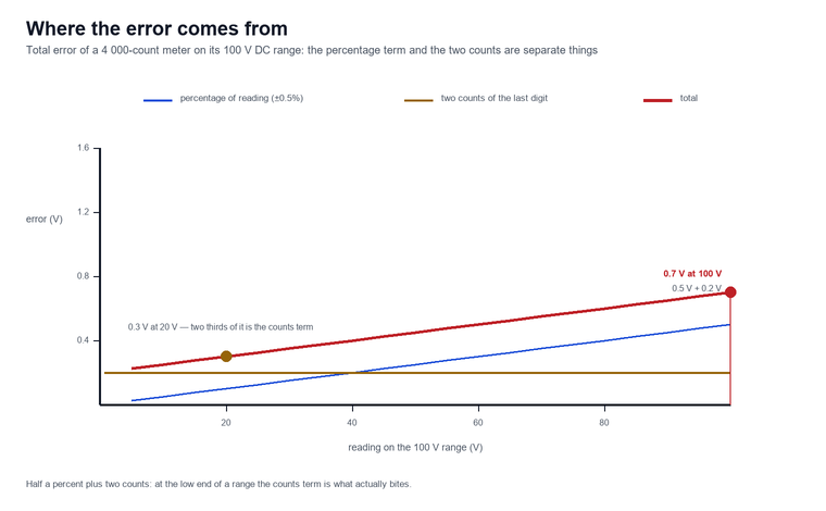
Accuracy is written as a sum, and the second term is usually the more revealing one. A meter quoted at ±(0.5 percent + 2) on DC volts incurs half a percent of the reading plus two counts of the least significant digit; on a 4 000-count instrument measuring 100.0 V that is 0.5 V plus two counts of 0.1 V, so about 0.7 V, which is roughly 0.7 percent of reading rather than the 0.5 percent the headline suggests — and that is before the conditions printed underneath it are taken into account. Which is exactly why comparing two meters on their headline number alone is close to meaningless.
The mechanism behind input impedance is the second trap, and it is worth spelling out. An input that draws almost no current cannot tell the difference between a conductor that is genuinely energised and one that is picking up charge capacitively from a live circuit running alongside it in the same tray. For example, a long parallel run can sit at tens of volts to earth with the supply off, and the reading collapses to a volt or two the moment anything resembling a load is applied; the standard measure is a low-impedance input — usually labelled LoZ or VFD — that deliberately loads the circuit long enough to separate the two cases. Purpose-built instrumentation takes the filtering route instead: the HF-GT-208 frequency selective multimeter specifies input impedance above 500 kΩ, holds ±(2 percent of reading + 0.1 mV) on its voltage input and keeps accuracy within 5 percent even with 10 000 times power-frequency interference present, which is an interference rejection ratio approaching 1 000 000:1.
Resolution and accuracy are then two different conversations, and conflating them is the last trap on the sheet: a 60 000-count meter resolves six times more finely than a 10 000-count one, but if its basic accuracy is two counts worse the extra digits are decoration. Traceability is the answer to whether either can be believed — and it comes from a calibration chain rather than from anything printed on the device, which is the point of reference metrology work such as NIST applied electrical metrology.
Test Setup: The Sequence That Keeps You Safe
Good technique costs nothing and prevents most of the accidents that a good meter cannot, and the sequence of checks around applying a digital multimeter for electricians to a live panel matters more than any feature on the dial.
The order is fixed and it is short. Before anything else, prove the meter itself on a known live source — a proved tester, a proved socket, anything independently known to be energised — because a meter that reads zero when it should read zero is indistinguishable from a dead circuit until you check it against something alive. Then take the reading on the circuit under test. Then prove the meter again on the same known source. If any of the three steps goes wrong, stop: the meter, the leads or the assumption about the source has failed, and none of the readings in between can be trusted. Only after all three steps does the measurement get used to authorise touching the circuit.
Four details turn that sequence into a habit that survives a busy shift:
- Lead condition first. Look at the insulation, look at where the probe meets the moulded handle, and look at whether tips are the retractable-sleeve type now covered by IEC 61010-031:2022; damaged leads fail silently and then catastrophically.
- Correct jack for the rotary position. Most blown input fuses come from leaving the lead in the current jack and moving the rotary switch to volts, which shorts the source through the shunt. IEC 61010-2-033:2023 added requirements aimed directly at input and range mismatch for exactly this reason.
- One hand where possible, the other behind your back or in your pocket, so that a shock path cannot run arm to arm across the chest.
- Read the category before you read the volts, every time, including on the panel you have worked on for ten years.
Where the work is the verification of protective measures rather than the measurement of a value, the governing document changes: IEC 61557-1:2019 sets the general requirements for measuring and monitoring equipment used to test electrical safety in low-voltage distribution systems up to 1 000 V AC and 1 500 V DC, and was revised to align its uncertainty figures with the ISO/IEC Guide 98-3 approach (IEC 61557-1:2019). A general-purpose multimeter is not automatically equipment for verifying protective measures, and the two are not interchangeable in a signed-off test record.
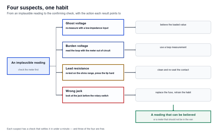
When the Reading Is Wrong: Four Usual Suspects
Most wrong readings are not meter failures; they are correct answers to a question nobody meant to ask of a digital multimeter for electricians, and four suspects account for almost all of them: capacitively coupled voltage, burden voltage, lead resistance and the wrong jack for the rotary position.
Ghost voltage is the first, and it is the one that sends crews looking for faults that do not exist. A conductor running alongside a live one for twenty metres picks up charge, and an input that draws no current holds that charge indefinitely, so the reading is real — it is just not a measurement of supply voltage. The check is deliberately loading the circuit with a low-impedance input, which either collapses the reading to a couple of volts or confirms that a real source sits behind it.
Burden voltage is the second, and it belongs to the current ranges. Every current measurement inserts a shunt, and the voltage dropped across it is subtracted from the circuit being measured — which is why a 4–20 mA loop can behave differently with the meter in circuit than without it, and why the answer is normally a separate loop measurement rather than a different meter.
Lead resistance is the third, and it is the reason continuity readings on a digital meter should always be followed by the resistance range rather than trusted from the buzzer. A poor contact between probe and terminal adds tens of milliohms that vanish and reappear depending on how hard the probe is pressed, and it looks exactly like an intermittent fault.
Wrong jack for the rotary position is the fourth and the most expensive. Lead in the amps jack, rotary on volts: the source is shorted through the shunt, the fuse opens — hopefully the fuse and not the meter — and the job stops. Some designs now interlock the jacks; where they do not, the habit is checking the jack before every rotary change.
Limitations and Boundaries
A digital multimeter for electricians is a measuring instrument, not a testing instrument, and that difference decides which jobs it can be used for: it measures what the network is doing, it does not prove that a protective measure works.
- It cannot verify protective measures. Insulation resistance has to be measured with insulation resistance equipment driven from its own source, and loop impedance and RCD testing belong to installers’ testers whose performance is defined by the relevant parts of the 61557 series rather than by the 61010 series.
- It cannot take the place of a proving unit or a voltage indicator designed for the safety case. Proving dead needs equipment made for proving dead, used in a defined sequence, on a circuit whose source is identified.
- It is not a clamp meter for everything. Reading current through the meter’s own jacks means opening the circuit, which changes the circuit; where that matters, a purpose-built clamp is the correct instrument and has its own family requirements.
- It cannot be trusted outside its category or its conditions. Category, working voltage, pollution degree and the stated environmental band are the boundaries of the safety case, and none of them is a matter of opinion.
FAQ
What rating should a digital multimeter for electricians have?
At least CAT III 600 V for anything that will be plugged into fixed wiring, and CAT IV 600 V where the work reaches the service entrance or an outdoor supply. CAT III covers distribution boards, wiring between the board and the socket, and fixed loads with short leads; CAT IV covers the origin of the installation from the meter back toward the transformer.
Why is CAT II missing from the label on a new meter?
Because it is not allowed there. Terminals of measuring circuits intended for mains voltage are marked CAT III or CAT IV with the nominal line-to-neutral voltage, and marking those terminals CAT II is not permitted under IEC 61010-2-033:2023. A CAT II marking elsewhere describes leads or other equipment — or a declaration that does not match the standard.
Are 7 functions enough, or do electricians need more?
Seven is enough for most general work provided the seven include AC and DC voltage, AC and DC current, resistance and continuity. What matters is which functions are counted: a meter with diode test, capacitance and frequency but no usable current range will spend its life sitting in the van while another tool does the work.
Why does my meter show voltage on a circuit I know is disconnected?
Capacitive coupling. A conductor beside a live one accumulates charge, and a high-impedance input draws too little current to drain it, so the reading is real voltage with no useful energy behind it. Re-measure with a low-impedance input: a genuine supply holds its reading, a phantom collapses towards zero.
How often should a handheld meter be calibrated?
Follow the manufacturer’s stated interval and shorten it whenever the meter has been dropped, exposed to moisture or used outside its stated conditions. The interval only means something if the calibration is traceable, which is what links a field reading to a national measurement standard.
Is a multimeter enough to verify an installation?
No. Verifying protective measures on low-voltage systems is covered by the 61557 series, and the equipment used for it — insulation testers, loop impedance testers, RCD testers — has performance requirements separate from the safety requirements that govern a multimeter. A multimeter measures; installation test equipment verifies.
Can I use the current ranges to measure a running motor?
Only within the meter’s stated current rating and only with the circuit opened, which usually means a shutdown. For anything else, a clamp meter is the safer instrument, and beyond a few hundred amps a clamp designed for the duty is the only realistic option.
Conclusion
A digital multimeter for electricians is chosen on four things — the category and transient rating printed beside the jacks, the functions actually present on the rotary switch, the mechanical construction that survives a year in a vehicle, and the honesty of the accuracy formula. Get those four right and the fifth, the reading itself, tends to take care of it; get the category wrong and nothing else on the specification sheet matters.
For the work that a multimeter cannot do — insulation testing, loop impedance, RCD verification, earthing — the electrical test instruments category covers the dedicated equipment, including the HF-GT-217 insulation resistance tester for insulation performance, the HF-GT-209 clamp ground resistance tester for earthing without auxiliary stakes, the HF-GT-208 frequency selective multimeter for measurements taken under heavy site interference, and the HF-LT-308 digital insulation resistance meter for single-hand insulation checks. Where a reading drives decisions about cable condition rather than circuit state, the cable testing and monitoring programme is the next step beyond a handheld meter. If you are selecting meters for a team and want the ratings checked against the panels your crews actually work on, contact us — we would rather argue about the category before someone touches the board than after.
References and Technical Sources
- IEC, Safety requirements for electrical equipment for measurement, control, and laboratory use — Part 1: General requirements, IEC 61010-1:2010, edition 3.0, published 10 June 2010 (consolidated with AMD1:2016) — measurement categories, impulse withstand levels and pollution degrees. webstore.iec.ch
- IEC, Part 2-033: Particular requirements for hand-held multimeters and other meters for domestic and professional use, capable of measuring mains voltage, IEC 61010-2-033:2023, edition 3.0, published 20 September 2023 — CAT III / CAT IV terminal marking, surge protective devices, fire and arc-flash protection of measuring circuits. webstore.iec.ch
- IEC, Part 031: Safety requirements for hand-held and hand-manipulated probe assemblies for electrical test and measurement, IEC 61010-031:2022, edition 3.0, published 22 December 2022 — probe types including Kelvin and non-contact probes, retractable-sleeve tips. webstore.iec.ch
- IEC, Electrical safety in low voltage distribution systems up to 1 000 V AC and 1 500 V DC — Equipment for testing, measuring or monitoring of protective measures — Part 1: General requirements, IEC 61557-1:2019, edition 3.0, published 26 July 2019 — general requirements for installation test equipment. webstore.iec.ch
- IEC, Degrees of protection provided by enclosures (IP code), IEC 60529:2013, edition 2.2, consolidated 1989 + AMD1:1999 + AMD2:2013, published 29 August 2013 — ingress protection codes. webstore.iec.ch
- NIST, Applied Electrical Metrology — measurement traceability for voltage, current and resistance calibration. nist.gov