

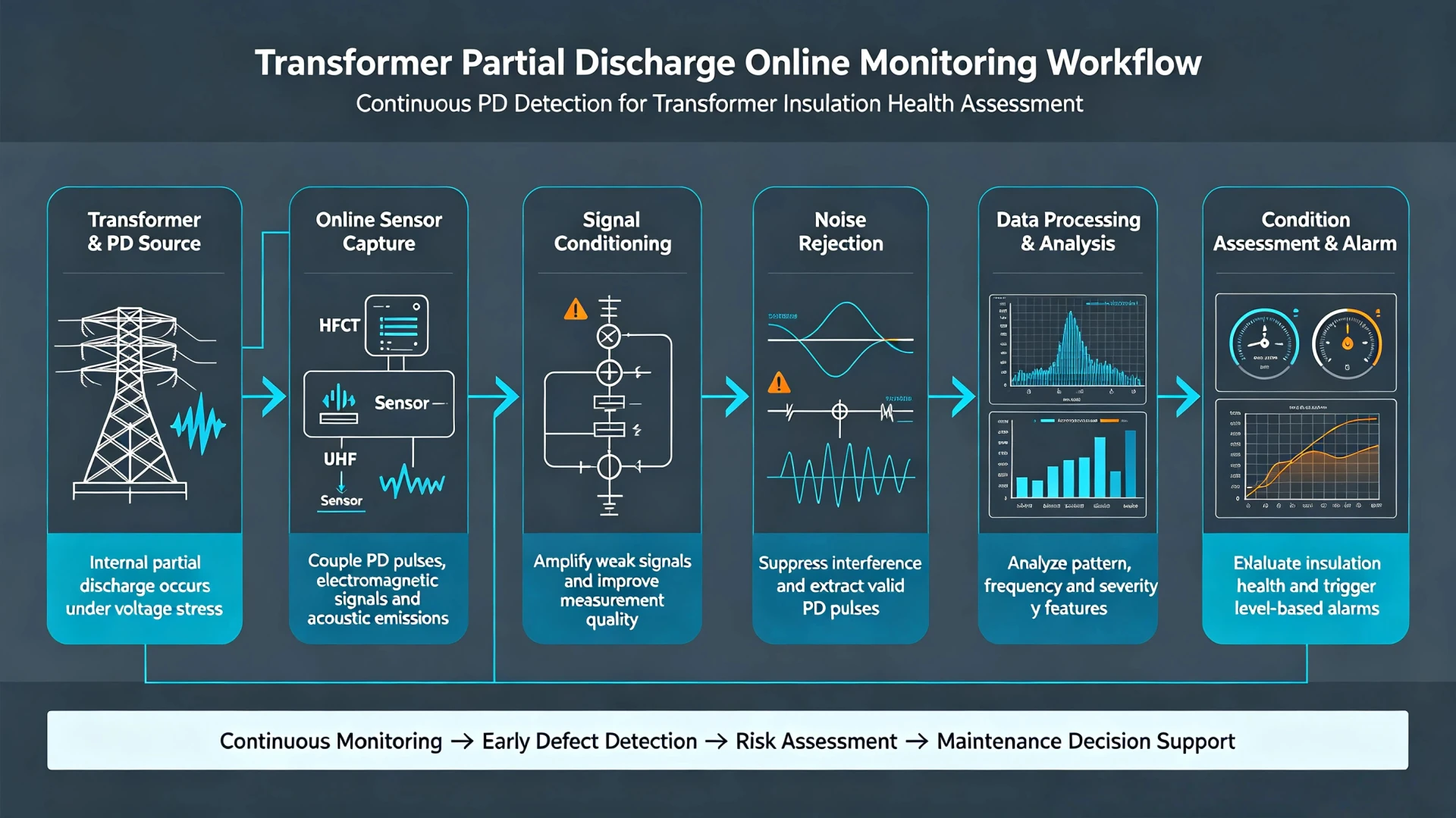
An online partial discharge monitoring system for transformers continuously detects and analyzes partial discharge (PD) activity while the transformer remains energized. Unlike periodic offline testing, online monitoring can collect PD data over extended operating periods and track changes in discharge activity under actual load and environmental conditions.
A typical online PD monitoring process includes sensor detection, signal acquisition, signal conditioning, noise rejection, PD pattern analysis, source localization, trend monitoring, and condition alarms. This article explains how these stages work together and what information an online transformer PD monitoring system provides for insulation condition assessment and maintenance planning.
What Is an Online Partial Discharge Monitoring System for Transformers?
An online partial discharge monitoring system is designed to monitor PD activity while the transformer remains energized and in normal service. It uses sensors installed on or around the transformer to continuously acquire discharge signals.
The system then processes these signals to extract useful information such as discharge magnitude, phase-resolved patterns, and event characteristics. This data is analyzed over time to identify changes in PD activity and establish trend information. When abnormal or preset thresholds are exceeded, the system generates alarms to notify operators.
Because monitoring is continuous, an online system can detect PD activity that may occur between periodic offline tests. It supports early detection of insulation problems, trend tracking, and condition-based maintenance decisions without requiring a transformer shutdown.
What Causes Partial Discharge in Transformer Insulation?
PD activities in operating power transformers mainly stem from internal insulation defects and operating environment changes, with typical causes including:
- Micro voids, cracks, and delamination inside oil-paper insulation
- Insulation aging, moisture ingress, and oil contamination after long-term operation
- Local electric field concentration caused by winding deformation or loose structural parts
- Surface contamination and discharge traces on bushing and insulation components
- Temperature fluctuation and load variation leading to insulation moisture migration
Why Is Partial Discharge a Warning Sign?
PD activity can provide an early indication of localized insulation deterioration. Changes in discharge magnitude, repetition rate, phase pattern, source location and long-term trends can help engineers assess whether insulation activity is stable or changing and determine whether further investigation is required.
How Does Transformer Partial Discharge Online Monitoring Work?
The entire workflow of industrial-grade transformer PD online monitoring follows a closed-loop technical logic:
PD Signal Generation → Sensor Capture → Signal Conditioning → Noise Rejection → Pattern Analysis → Fault Localization → Trend Monitoring → Condition Alarm & Assessment.
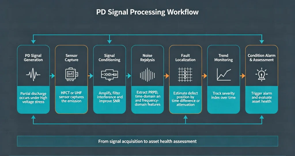
Each link is standardized and verified per IEC high-voltage testing specifications to ensure monitoring accuracy and stability.
Step 1 — PD Activity Generates Detectable Physical Signals
When partial discharge occurs in transformer oil-paper insulation, instantaneous pulse current, high-frequency electromagnetic waves, and acoustic emission waves are generated synchronously. These physical signals propagate through transformer oil, tank walls, and grounding lines, forming effective detection sources for online monitoring systems.
Different defect types produce distinct signal characteristics, laying the foundation for subsequent PD pattern recognition and fault classification.
Step 2 — Professional PD Sensors Capture Multi-Dimensional Signals
Single detection technology is easily interfered by on-site substation noise. Mature online PD monitoring systems adopt a hybrid detection scheme of HFCT + UHF + AE to achieve cross-verification and full-coverage signal acquisition. The core detection sensors and their functions are shown in the table below:
| Detection Method | Core Sensor | Captured Signal | Core Application Purpose |
|---|---|---|---|
| HF (High Frequency) | HFCT High-Frequency Current Transformer | High-frequency grounding pulse current | Accurate quantification of PD apparent charge, suitable for standardized PD measurement compliant with IEC 60270 |
| UHF (Ultra-High Frequency) | Meandered PIFA UHF Antenna | 280–353 MHz electromagnetic wave signal | High-sensitivity detection of internal weak PD, strong anti-interference against external corona noise |
| AE (Acoustic Emission) | Active Dielectric Window (ADW) Ultrasonic Sensor | 120–270 kHz acoustic wave signal | Auxiliary PD source localization, eliminating electromagnetic interference false alarms |
Compared with traditional single-sensor schemes, the three-in-one hybrid detection system improves low-intensity PD detection sensitivity by up to 7.8 times and effectively solves the problem of missed and false detection in complex substation electromagnetic environments.
Step 3 — Signal Acquisition and Conditioning
Original PD signals collected by sensors feature weak amplitude, mixed clutter, and inconsistent frequency bands. The system performs standardized signal processing through a dedicated hardware module:
- Low-noise amplification and bandpass filtering for UHF and AE signals
- Raw high-frequency signal retention for HFCT to ensure charge quantification accuracy
- 40 MS/s high-speed sampling and 16-bit high-precision digitization
- Unified time stamping and multi-channel signal synchronization
This process converts disordered physical signals into standardized digital data for subsequent algorithm analysis.
Step 4 — Noise Rejection and Anti-Interference Processing
The biggest challenge of on-site online PD monitoring is distinguishing genuine PD pulses from massive substation interference signals, including line corona discharge, switching operation noise, radio frequency interference, and mechanical vibration noise.
The system adopts a multi-dimensional noise suppression mechanism:
- Hardware shielding: Aluminum alloy shielded housing and optical fiber signal transmission isolate external electromagnetic interference
- Algorithm filtering: Frequency domain filtering removes fixed-bandwidth background noise
- Multi-sensor cross-correlation judgment: Only signals synchronously captured by HFCT, UHF, and AE sensors are identified as valid PD events; single-channel abnormal signals are judged as interference
This mechanism greatly improves monitoring accuracy and avoids invalid alarms caused by on-site environmental noise.
Step 5 — PRPD Pattern Analysis and PD Feature Extraction
Phase-Resolved Partial Discharge (PRPD) pattern analysis is the core technical means for professional PD fault diagnosis, compliant with IEC 60270 international standards. The system maps each PD pulse’s amplitude, quantity, and occurrence phase angle relative to the AC voltage cycle to form a unique discharge fingerprint.
Different insulation defects correspond to fixed PRPD features:
- Internal void discharge: Symmetric pulse distribution near voltage zero crossing
- Surface discharge: Asymmetric pulse distribution concentrated in positive/negative half-cycles
- Electrode corona discharge: Narrow pulse clusters near voltage peak values
Step 6 — PD Source Identification and Spatial Localization
Signal detection only confirms the existence of PD activity, while localization determines the exact fault location. The system uses the time difference of arrival (TDOA) trilateration algorithm to calculate the spatial position of the PD source based on the time difference of multi-group AE and UHF signal reception.
This function helps maintenance personnel quickly locate latent defects such as winding insulation damage, internal voids, and surface discharge, realizing precise targeted maintenance.
Step 7 — Long-Term Continuous Trend Monitoring
The core advantage of online monitoring over offline testing is continuous dynamic tracking. The system records PD pulse quantity, amplitude, and energy data in real time, and generates trend curves for 15-minute, 1-hour, 1-day, and 30-day cycles.
Combined with transformer operating parameters (oil temperature, operating voltage, load rate) synchronized with the SCADA system, it can identify abnormal PD surge caused by temperature rise, load fluctuation, and overvoltage, realizing early prediction of defect deterioration.
Step 8 — Intelligent Alarm and Engineering Condition Assessment
The system does not simply judge transformer failure but outputs professional assessment results based on multi-dimensional data:
- Threshold alarm: Trigger early warning/alarm when PD apparent charge or pulse quantity exceeds the standard range
- Trend alarm: Alert abnormal continuous rise of PD activity
- Comprehensive assessment: Combine PD pattern, trend, and operating environment data to output insulation health reports
All diagnostic results provide objective data support for engineers’ maintenance decisions.
What Sensors Are Used for Online Transformer PD Monitoring?
HFCT High-Frequency Current Transformer Sensor
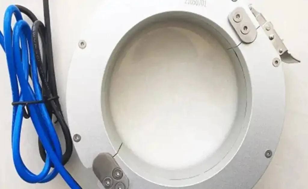
Installed on transformer grounding wires or neutral point grounding loops, HFCT sensors capture high-frequency pulse currents generated by PD. The MnZn ferrite core structure ensures ultra-high sensitivity (1.48 times higher than commercial mainstream sensors) and a wide bandwidth of 250 kHz–25.5 MHz, supporting standard IEC 60270 charge quantification.
UHF Meandered PIFA Antenna Sensor
Embedded in transformer insulation windows, the optimized meandered planar inverted-F antenna adapts to the 280–353 MHz high-frequency band of oil-paper insulation PD signals. It features low standing wave ratio and strong anti-interference, with 7.8 times higher sensitivity for weak internal PD detection than traditional disk antennas.
AE Acoustic Emission Sensor (ADW Integrated)
Built into the active dielectric window and directly immersed in transformer oil, the AE sensor avoids signal attenuation caused by tank wall shielding. Its detection sensitivity is 5.8 times higher than traditional external wall-mounted sensors, effectively capturing low-energy acoustic signals of internal PD.
Why Use Multiple PD Detection Methods Simultaneously?
Single detection technology has inherent limitations: UHF is susceptible to radio interference, AE is disturbed by mechanical vibration, and HFCT is affected by external grounding noise. The hybrid scheme realizes complementary advantages:
- Cross-verification eliminates false and missed detections
- Multi-dimensional data improves fault type identification accuracy
- Synergistic localization improves PD source positioning precision
- Strong adaptability to complex substation operating environments
Key Parameters Monitored by Online Transformer PD Systems
The system outputs standardized quantifiable parameters for transformer insulation health assessment, as shown in the table below:
| Monitored Parameter | Practical Engineering Significance |
|---|---|
| PD Apparent Charge (pC) | Core index for judging PD severity, compliant with IEC 60270 standard |
| PD Repetition Rate | Reflects the activity frequency of insulation defects |
| PRPD Phase Distribution | Identifies PD type (internal void, surface, corona discharge) |
| PD Amplitude & Energy Trend | Judges defect development speed and deterioration trend |
| Multi-Sensor Correlation Data | Distinguishes genuine PD from environmental interference |
Online vs Offline PD Monitoring
| Factor | Online | Offline |
|---|---|---|
| Transformer status | Energized | De-energized |
| Monitoring | Continuous | Periodic |
| Operating condition | In service | Test condition |
| Outage | Normally not required | Required |
For a detailed comparison of online and offline transformer PD testing, see Online Partial Discharge Testing for Transformers.
Typical Transformer Faults Detected by PD Monitoring
PD monitoring focuses on insulation system defects (the main cause of transformer catastrophic failure), covering four core fault types:
- Internal Insulation Defects: Void discharge, delamination, and aging inside oil-paper insulation
- Surface Discharge: Discharge on insulation surfaces caused by contamination and dampness
- Corona Discharge: Electric field concentration discharge at sharp structural parts and aging bushings
- Latent Aging Defects: Gradual insulation deterioration caused by long-term temperature cycling and load fluctuation
Note: PD monitoring is a professional insulation condition diagnostic method, not a full-scale transformer fault monitoring system. It works with DGA, temperature, and vibration monitoring to form a complete transformer health assessment system.
Core Benefits of Online Transformer PD Monitoring
- Early Fault Warning: Detects latent insulation defects weeks or months before failure, avoiding sudden breakdowns
- No Operational Interruption: No transformer outage required during monitoring, ensuring power supply continuity
- Support Condition-Based Maintenance: Replaces blind periodic maintenance with data-driven targeted maintenance
- Reduce Operational Risks: Effectively cut unplanned outage losses and equipment replacement costs
- Asset Life Management: Track long-term insulation aging trends to optimize transformer asset operation strategy
Main Application Scenarios
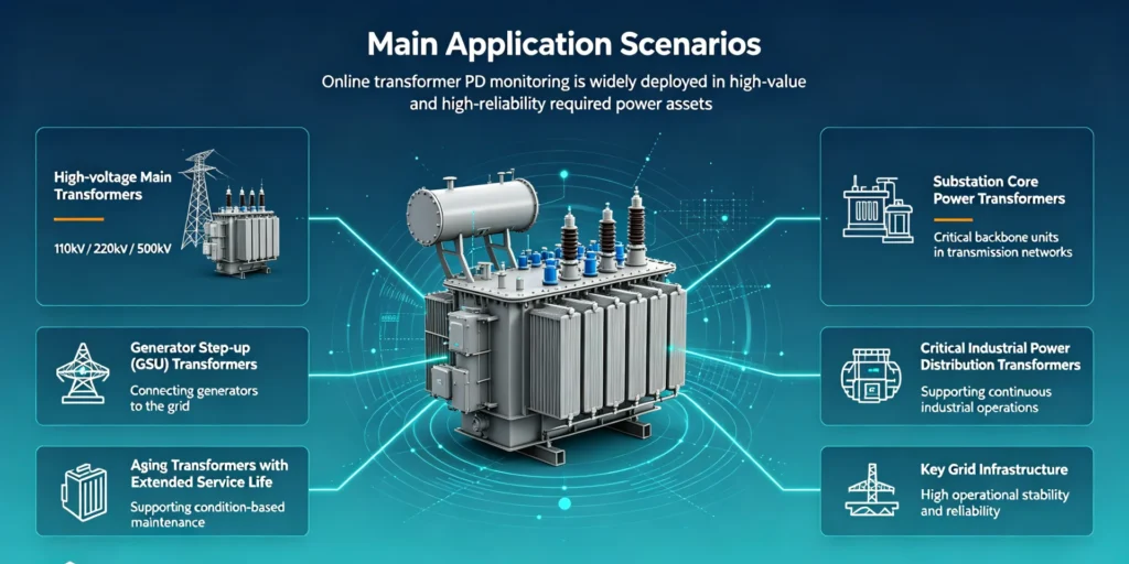
Online transformer PD monitoring is widely deployed in high-value and high-reliability required power assets:
- High-voltage main transformers (110kV/220kV/500kV)
- Substation core power transformers
- Generator step-up (GSU) transformers
- Critical industrial power distribution transformers
- Aging transformers with extended service life
- Key grid infrastructure requiring high operational stability
Key Considerations for Online Transformer PD Monitoring
- Transformer type and voltage level – determines suitable sensor types and monitoring configuration
- Sensor installation conditions – availability of reserved interfaces, grounding access, or tank wall mounting points
- Noise environment – site interference level affects sensor selection and sensitivity settings
- Required monitoring continuity – continuous online monitoring versus periodic data collection
- Communication and data integration – how PD data will be transmitted and integrated into existing monitoring platforms
For a detailed device-selection framework, see How to Choose a PD Monitoring Device for Power Transformer.
PD Monitoring vs Other Transformer Condition Monitoring Methods
Each transformer monitoring technology has independent positioning and forms complementary protection for equipment health:
| Monitoring Method | Core Monitoring Object | Monitoring Characteristics |
|---|---|---|
| Partial Discharge Monitoring | Insulation micro-defects and discharge activity | Earliest warning of latent insulation faults |
| DGA Monitoring | Insulation aging and overheating decomposition gas | Judges medium-term and severe insulation faults |
| Temperature Monitoring | Transformer thermal operating state | Reflects load and heat dissipation conditions |
| Vibration Monitoring | Mechanical structure looseness and deformation | Monitors mechanical operating faults |
Frequently Asked Questions
1. What Is an Online Partial Discharge Monitoring System for Transformers?
It is an industrial-grade real-time monitoring technology that uses multi-sensor fusion to continuously detect, analyze, and trend transformer insulation partial discharge signals under energized operating conditions, realizing early warning of latent insulation defects.
2. Can online PD monitoring work while the transformer is energized?
Yes. The system is designed for live-line operation, requiring no transformer outage and capturing PD characteristics under real operating load and temperature conditions.
3. What sensors are core to transformer online PD monitoring?
HFCT high-frequency current transformers, UHF broadband antennas, and AE acoustic emission sensors. The hybrid three-sensor scheme is the most reliable industrial solution.
4. What is the difference between online and offline PD testing?
Offline testing is periodic outage detection with only static data; online monitoring provides 24/7 continuous dynamic monitoring and defect trend analysis, realizing early fault prediction.
5. Can online PD monitoring locate partial discharge sources?
Yes. Through multi-channel signal time difference analysis and trilateration algorithm, the system can accurately locate the spatial position of internal PD defects.
6. Does partial discharge mean transformer failure?
No. Tiny and stable PD activity is normal in aging transformers. Only continuous rising PD intensity, abnormal pattern changes, and high-energy discharge events are warning signs of impending insulation failure.
7.What data does an online transformer PD monitoring system collect?
An online transformer PD monitoring system typically collects:
- PD pulse activity – detection of discharge events and their repetition
- Apparent charge – estimated discharge magnitude where applicable
- Phase-resolved patterns – PRPD/PRPS data for identifying discharge characteristics
- Trend data – changes in PD activity over time
- Alarm events – records of threshold exceedances and triggered alarms
- Sensor correlation data – combined inputs from multiple sensors for cross-verification
Conclusion
Online transformer partial discharge monitoring provides continuous visibility into insulation condition by detecting PD signals, analyzing discharge characteristics, and tracking activity over time. It supports early fault detection, condition-based maintenance, and reliable operation of substation, GSU, and industrial transformers.
If you are evaluating an online PD monitoring solution for a substation, GSU or industrial transformer, our team can help assess the transformer configuration, sensor requirements and communication interface.
For more details, see our Transformer Partial Discharge Online Monitoring Device.
Technical References & Data Sources
- IEC 60270: High-voltage test techniques – Partial discharge measurements
- IEC 61850: Substation automation system communication standard
- Sikorski, W., et al. (2020). On-Line Partial Discharge Monitoring System for Power Transformers Based on HF, UHF and AE Signal Detection. Energies 13(12), 3271
- IEEE Technical Topic: Partial Discharge Measurement & Insulation Condition Assessment
- CIGRE Working Group A2.37: Transformer Damage Cause Statistical Report
[…] How Does a Transformer Partial Discharge Monitoring Device Work? […]
[…] How Online Transformer PD Testing Works […]