

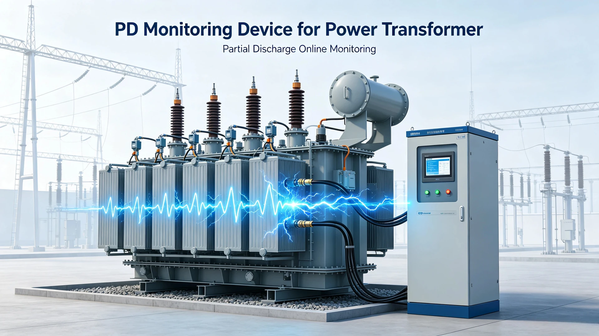
Choosing a PD monitoring device for a power transformer depends on the transformer type, insulation condition, monitoring objectives, field installation constraints, compatible PD detection technologies, sensitivity requirements, and the need for continuous online monitoring.
Power transformers are core assets of power grids, industrial power systems, and renewable energy substations. Partial discharge (PD) is the primary precursor of transformer insulation aging and sudden failure. Selecting a mismatched PD Monitoring Device for Power Transformer leads to invalid data, missed insulation defects, excessive investment, or unplanned transformer outages.
This practical buyer’s guide helps EPC engineers, substation O&M teams, and power project owners complete full-standard device selection step by step. We cover detection method comparison, online/offline scenario matching, core parameter verification, sensor configuration, installation specifications, cost-influencing factors, and supplier evaluation, delivering a fully actionable PD monitoring device selection workflow for power transformers.
What Is a PD Monitoring Device for a Power Transformer?
What Does the Device Monitor?
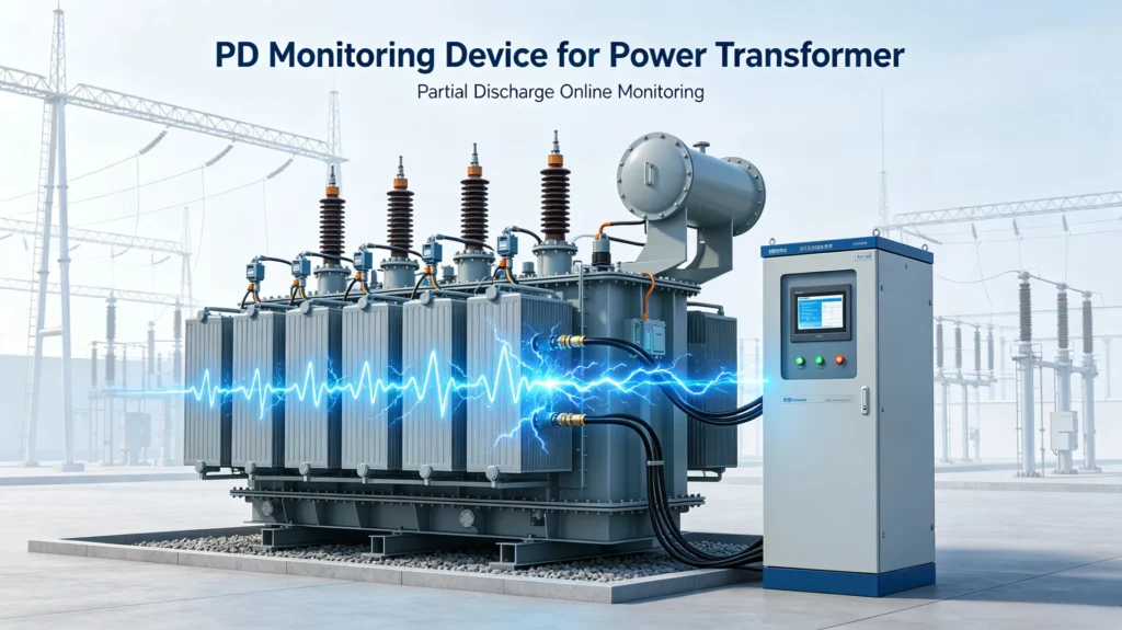
A professional transformer PD monitoring device is a dedicated condition monitoring system designed for high-voltage transformer insulation diagnosis. It captures and analyzes partial discharge signals generated by internal insulation defects, providing quantitative and qualitative data support for transformer health assessment. Core monitoring objects include:
- Real-time partial discharge activity and pulse frequency
- PD magnitude, intensity, and phase distribution characteristics
- Occurrence regularity and abnormal mutation of PD events
- Progressive deterioration trend of transformer insulation
- PD source localization and defect characteristic identification
- Long-term cumulative changes of insulation partial discharge under operating conditions
When Should You Consider a PD Monitoring Device?
PD monitoring is not required for all transformers. Reasonable deployment based on application scenarios avoids over-investment or monitoring missing errors.
For New Power Transformers
Essential for factory acceptance testing (FAT) and site commissioning (SAT) of new transformers:
- Establish baseline PD data archives for subsequent life cycle comparison
- Verify no transportation, installation or commissioning-induced insulation damage
- Confirm factory insulation manufacturing quality compliance
For In-Service Transformers
Priority deployment for operating transformers with potential risks:
- Transformers with 10+ years of operation and obvious insulation aging characteristics
- Units with gradually increased PD activity in periodic tests
- Transformers with historical insulation faults, oil deterioration or partial overheating problems
- High-value, core backbone transformers that affect regional power supply
For Critical Substation Scenarios
Continuous PD monitoring is mandatory for high-reliability required scenarios:
- Thermal power, hydropower and new energy power generation plants
- High-voltage transmission hub substations
- Key industrial substations (manufacturing, petrochemical, data center power supply)
- Renewable energy gathering substations (wind power, photovoltaic)
For Continuous Condition Monitoring
Online PD monitoring is the optimal solution for transformers where shutdown is difficult, costly, or prohibited. It realizes 24/7 uninterrupted monitoring, captures transient PD events caused by load fluctuation, switching surge and temperature change, and provides early warning of gradual insulation failure.
Key Factors When Choosing a PD Monitoring Device for a Power Transformer
This is the core selection checklist for engineering applications. All factors are centered on field adaptability and monitoring accuracy to avoid blind selection.
1. Transformer Type and Voltage Level Compatibility
The monitoring device and sensor configuration must match the transformer’s structural parameters, which directly determines installation feasibility and monitoring effectiveness. Key evaluation indicators:
- Transformer type: oil-immersed / dry-type, power / distribution / generator / autotransformer
- Voltage level: 10kV, 35kV, 110kV, 220kV, 500kV and above
- Rated capacity, winding quantity and bushing structure
- Reserved monitoring interfaces and on-site installation space
Core principle: The PD monitoring system must be fully compatible with the transformer construction and available installation points to ensure non-destructive installation and stable signal acquisition.
2. Choose the Right PD Detection Method
No single detection technology adapts to all working conditions. Select the matching method according to on-site electromagnetic interference, installation conditions and monitoring goals. The mainstream industrial detection methods are compared as follows:
| Detection Method | Typical Sensor | Main Advantage | Typical Application Scenarios |
|---|---|---|---|
| UHF PD Monitoring | UHF antenna sensor | Strong EMI resistance, high sensitivity, accurate defect localization | Online monitoring of high-voltage main transformers, complex electromagnetic environment substations |
| HFCT PD Detection | High-frequency current transformer | Non-invasive, easy retrofitting, no transformer shutdown required | In-service transformer renovation, grounding wire PD signal acquisition |
| Ultrasonic PD Detection | Ultrasonic acoustic sensor | Direct acoustic signal capture, intuitive local defect judgment | Auxiliary localization of internal discharge defects, offline troubleshooting |
| Electrical/HF Detection | Electrical coupling sensor | Direct electrical measurement, compliant with IEC 60270 standard | Factory offline testing, commissioning acceptance detection |
Online vs Offline PD Monitoring: Which Configuration Fits Your Project?
| Factor | Online Monitoring | Offline Testing |
|---|---|---|
| Transformer status | In service | De-energized |
| Monitoring mode | Continuous or scheduled | Test session |
| Installation | Permanent/installed sensors | Temporary test setup |
| Main purpose | Trend and condition monitoring | Testing and diagnosis |
| Typical application | Critical in-service assets | FAT, commissioning, maintenance |
For a detailed comparison, see Online vs Offline Partial Discharge Testing for Transformers.
What Technical Specifications Should You Check?
Parameters determine monitoring accuracy and system stability. Avoid selecting equipment only by price; core parameters must be verified one by one, and the practical significance of each parameter is explained below:
| Specification | What to Check | Why It Matters |
|---|---|---|
| Detection sensitivity | Minimum detectable signal / noise performance | Determines usable signal quality |
| Frequency response | Match the selected detection method | Affects signal acquisition |
| Monitoring channels | Required number of measurement points | Determines coverage |
| Data acquisition | Sampling, synchronization, storage | Affects data quality |
| PD analysis | PRPD, trend, event recording | Supports engineering assessment |
| Alarm functions | Thresholds, events, notifications | Supports abnormal-event management |
| Communication | Available interfaces/protocols | Determines system integration |
How to Choose PD Sensors for a Power Transformer
Sensors are the core of signal acquisition. Unmatched sensors will directly lead to invalid monitoring data. Targeted selection standards for three mainstream sensors are as follows:
UHF Sensors
Key selection points: sensor frequency response consistency, high-sensitivity induction capability, transformer tank installation matching degree, and outdoor environmental adaptability. Installation locations are usually transformer tank reserved detection ports, ensuring no dead angle for electromagnetic signal acquisition.
HFCT Sensors
Key selection points: matching with grounding conductor diameter, stable low-frequency response, narrow anti-interference performance, and on-site installation space. The sensor is clamped on the transformer grounding wire, requiring no wire cutting, ensuring safe and convenient retrofitting.
Ultrasonic Sensors
Key selection points: high acoustic sensitivity, low environmental noise interference, stable contact installation. Installed on the outer wall of the transformer tank, used for auxiliary verification of local discharge defects, suitable for offline troubleshooting and online auxiliary monitoring.
How Many PD Sensors Does a Power Transformer Need?
There is no fixed standard sensor quantity. The configuration depends on transformer volume, compartment structure, winding quantity, monitoring objectives and PD localization accuracy requirements. Large-capacity multi-compartment high-voltage transformers require multi-point sensor layout to achieve full coverage monitoring; small distribution transformers can adopt simplified single-point or dual-point configuration to balance cost and effect.
Software and Data Analysis Features to Look For
Customers purchase a complete set of monitoring solutions including hardware, sensors, software and data services. Software functions determine the final application value of the device:
- Real-Time PD Monitoring: Real-time display of PD intensity, pulse quantity and operating status
- PRPD Pattern Display: Professional phase-resolved discharge pattern analysis for defect identification
- Long-Term Trend Analysis: Track PD activity changes in hours, days, months and years to judge insulation aging trend
- Alarm and Event Management: Automatic recording of abnormal events, hierarchical alarm and log traceability
- Historical Data Storage: Long-term data retention and export, supporting regular health report generation
- Remote Monitoring and Communication: Support Ethernet, RS485, Modbus, IEC 61850 and other mainstream protocols, compatible with substation SCADA and automatic monitoring platforms
Installation Considerations for Transformer PD Monitoring
Sensor Installation Location
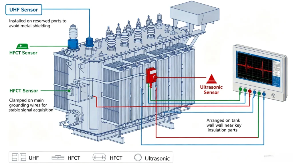
UHF sensors are installed on transformer tank reserved ports to avoid shielding by metal structures; HFCT sensors are installed on main grounding wires to ensure stable signal acquisition; ultrasonic sensors are arranged on the tank wall near key insulation parts for local signal capture.
Electromagnetic Interference Suppression
Substation switching equipment, high-frequency signals and radio interference will affect PD monitoring accuracy. The system must have built-in EMI filtering function, and the installation position should avoid high-interference equipment such as circuit breakers and isolating switches.
Grounding and Shielding Processing
Standardized grounding of monitoring host and sensors, matching professional shielding lines, eliminating grounding loop interference, ensuring long-term stable operation of the system.
Environmental Adaptability
The equipment must adapt to substation high temperature, low temperature, humidity and outdoor rain and dust environment, with industrial-grade protection level to ensure all-weather stable operation.
System Integration Compatibility
The PD monitoring system should support seamless docking with existing substation condition monitoring platforms, SCADA systems and substation automation systems, avoiding independent isolated data systems.
PD Monitoring Device Selection Guide by Application
Quick matching selection table for different engineering scenarios, helping engineers complete rapid decision-making:
| Application Scenario | Recommended Monitoring Solution |
|---|---|
| New transformer commissioning & acceptance | Offline PD testing + baseline data recording |
| Critical in-service transformer daily monitoring | Online multi-sensor continuous monitoring |
| Existing transformer monitoring renovation | HFCT non-invasive retrofitting solution |
| Strong electromagnetic interference substation | UHF-based anti-interference monitoring system |
| Long-term insulation trend tracking required | Online multi-channel full-data monitoring |
| PD source localization and defect troubleshooting | UHF + ultrasonic multi-sensor combined monitoring |
| Temporary fault diagnosis and testing | Portable offline PD detection device |
Common Mistakes When Choosing a Transformer PD Monitoring Device
Summarize industry common selection pitfalls to help teams avoid engineering risks and investment waste:
- Choosing only by low price: Ignoring core parameters, anti-interference performance and after-sales service, resulting in frequent false alarms and invalid monitoring
- Ignoring on-site background noise: Purchasing conventional equipment for strong interference substations, leading to unrecognizable valid signals
- Mismatched sensor configuration: Selecting sensors without combining transformer structure and installation space
- Overemphasizing sensitivity without checking signal quality: High sensitivity without anti-interference capability causes massive invalid data
- Focusing on hardware only, ignoring software functions: Advanced hardware without professional data analysis software cannot form effective diagnosis conclusions
- Neglecting system integration requirements: Equipment cannot dock with existing substation platforms, resulting in data isolation
- Blind installation without clear monitoring strategy: Unreasonable sensor layout leads to incomplete monitoring coverage
PD Monitoring Device Selection Checklist (Full Project Standards)
Engineering-grade procurement checklist for one-click verification of all selection indicators:
1. Transformer Basic Information
- Transformer type & insulation type
- Rated voltage & rated capacity
- Winding quantity & compartment structure
2. Monitoring Demand Confirmation
- Online continuous monitoring or offline periodic testing
- Single PD detection or PD source localization required
- Number of monitoring points & coverage range
3. Core Technical Requirements
- Matching detection technology (UHF/HFCT/ultrasonic/combined)
- Effective frequency range & detection sensitivity
- Monitoring channel quantity & sampling performance
- PRPD analysis, trend analysis & alarm functions
- Data storage cycle & export function
4. System Integration Requirements
- Communication protocol compatibility (Modbus/IEC 61850 etc.)
- SCADA and substation platform docking capability
- Remote access and remote maintenance function
5. Supplier Service Requirements
- Professional sensor configuration scheme
- On-site installation guidance & commissioning service
- Long-term software updates & technical support
- Official calibration documents & test reports
How Much Does a Transformer PD Monitoring Device Cost?
PD monitoring device pricing has no fixed standard, affected by multiple engineering factors. Core cost influencing factors include:
- Adopted detection technology and solution complexity
- Number of monitoring channels and sensor configuration quantity
- Online permanent system or portable temporary test equipment
- Professional data analysis software and alarm system functions
- System integration and protocol docking requirements
- PD source localization and multi-scene anti-interference capability
- On-site installation, commissioning and after-sales technical services
Engineering cost suggestion: For core high-voltage transformers, equipment procurement cost should not be the only evaluation standard. The economic loss caused by a single unplanned transformer outage is far higher than the monitoring system investment. Long-term monitoring value can effectively reduce asset operation risks.
How to Evaluate a PD Monitoring Device Supplier?
Equipment quality and service capability determine the long-term stable operation of the monitoring system. Key supplier evaluation standards:
1. Complete Standard Technical Documentation
Suppliers shall provide official datasheets, user manuals, sensor specification documents, communication protocol descriptions and standard installation drawings to ensure project implementation standardization.
2. Formal Testing and Calibration Qualifications
The equipment shall pass industry standard calibration and provide valid test reports, complying with IEC and IEEE transformer PD monitoring specifications, ensuring monitoring data accuracy and credibility.
3. Rich On-Site Application Experience
Priority shall be given to suppliers with mature application cases in power substations, power plants, industrial power systems and renewable energy projects, with verified field adaptation capabilities.
4. Full-Cycle Technical Support
Provide pre-sales engineering scheme customization, equipment configuration guidance, on-site installation commissioning, software debugging, after-sales fault handling and long-term technical consultation full-cycle services.
Frequently Asked Questions
1. What is a PD monitoring device for a power transformer?
A PD monitoring device for a power transformer is a system that detects, acquires, analyzes and monitors partial discharge activity in transformer insulation. It provides diagnostic information for insulation condition assessment.
2. How do I choose a PD monitoring device for a power transformer?
Selection should be based on transformer type and construction, installation conditions, noise environment, testing mode and monitoring objective. The device should match the required sensor types, measurement capability and communication needs.
3. Which PD detection method should I choose for a power transformer?
This depends on transformer structure, installation conditions, noise environment and monitoring objective. UHF, HFCT and acoustic methods detect different physical signals and offer different strengths. No single method is universally the best choice.
4. What sensors are used for transformer PD monitoring?
Common sensor types include UHF sensors, HFCT sensors and acoustic (ultrasonic) sensors. They may be used individually or in combination.
5. How many PD sensors does a transformer need?
There is no universal number. The required number depends on transformer size and construction, monitoring coverage objectives, sensor type, and whether localization is required.
6. Can a PD monitoring device be used on an energized transformer?
Some online configurations are designed for in-service monitoring, but installation requirements depend on sensor type, transformer design and safety procedures.
7. What technical specifications should I compare?
Key specifications include sensitivity, frequency response, number of channels, acquisition capability, analysis functions, alarm functions and communication interface.
8. How much does a transformer PD monitoring device cost?
Cost depends on sensor type and quantity, number of channels, measurement and analysis capability, communication and integration requirements, installation complexity and project scope.
Conclusion
The standardized selection logic of power transformer PD monitoring devices follows a clear engineering workflow: Confirm transformer characteristics → Clarify monitoring objectives → Select online/offline mode → Match detection technology → Optimize sensor configuration → Verify core technical parameters → Check software and integration functions → Evaluate supplier service capability.
Reasonable selection of PD monitoring equipment can effectively identify latent insulation risks, reduce unplanned outage losses, and realize scientific condition-based maintenance of transformers, which is an important guarantee for the safe and stable operation of power equipment.
CTA: If you are selecting a PD monitoring device for a power transformer, provide your transformer voltage level, rated capacity, equipment type, on-site monitoring requirements and preferred installation method. Our professional engineering team can customize a targeted PD monitoring configuration scheme for your project.
Technical Reference Standards & Data Sources
- IEC 60270:2000+AMD1:2015, High-voltage test techniques – Partial discharge measurements
- IEC 60076-3:2013, Power transformers – Part 3: Insulation levels, dielectric tests and external clearances in air
- IEC TS 62478, High-voltage equipment – Measurement of partial discharges by electromagnetic and acoustic methods
- IEEE C57.113-2023, Recommended Practice for Partial Discharge Measurement in Liquid-Filled Power Transformers and Shunt Reactors
- IEEE C57.160-2023, Guide for the Electrical Measurement of Partial Discharges in High Voltage Bushings and Instrument Transformers
- ISO 18095:2018, Condition monitoring and diagnostics of power transformers