

Author: Leon Zhang — Baoding Houfeng Trading Co., Ltd
Technical review: Power Testing Engineering Team — Senior High-Voltage Test Engineer, 14 years in substation and PV commissioning
Last updated: 21 October 2026
A power tester is the handheld or bench instrument that a technician uses to prove an electrical circuit is safe and functioning before it is trusted on a live system, and choosing the right one starts with the single question of what fault it must reveal rather than how many digits the display shows. This guide walks plant, facility and solar engineers through the four families of test instrument, the specifications that actually separate a usable unit from a toy, the commissioning and safety steps that protect the operator, and how to match the tool to the job without overpaying for features that never leave the case.
Key Takeaways
- The instrument is defined by the fault it finds: insulation breakdown, continuity loss, residual-current danger, PV string mismatch or power-quality distortion each calls for a different device, and no single box does all of them well.
- An ir tester is the de-energized insulation-resistance check governed by IEC 61557-2:2019, while a solar power tester follows the IEC 62446-1:2016 commissioning regime for grid-connected PV arrays, and an electric power tester sits on the live side measuring voltage, current and harmonics.
- Test voltage rating, measurement category (CAT III or CAT IV) per IEC 61010-1:2010, and the resolution of the smallest reading decide whether the tool is safe and credible on a given plant.
- Buy the function you will use weekly, not the specification sheet; a 5 kV insulation tester is worthless on a 48 V battery bank, just as a plug-in power-quality analyzer cannot prove a cable is dead.
- The kit is only as good as the pre-test isolation and the lockout-tagout around it; the biggest field failures come from testing the wrong circuit, not from a weak meter.
What the Instrument Must Reveal
Any calibrated instrument that measures an electrical quantity to confirm a circuit, machine or array is within its safe operating envelope hides at least four distinct jobs that share a screen but not a method. The first job is the de-energized proof of insulation and continuity, the second is the residual-current and trip verification on protective devices, the third is the energized power-quality survey of a live distribution system, and the fourth is the commissioning of a photovoltaic array against its design curve. Treating them as one product is the most common buying mistake we see in tenders. Any box that promises all four jobs in a single case usually delivers none of them to a standard you could defend in an audit.
The internal architecture of a credible unit is simpler than buyers assume: a precision voltage or current source, a high-impedance measurement front end, a sampling analog-to-digital converter, and a processor that turns raw samples into a resistance, a phase angle or a waveform. What separates a professional instrument from a consumer multimeter is not the display, it is the isolation rating of that front end and the traceability of its calibration to a national laboratory.
Key terms
- Insulation resistance is the opposition offered by cable and winding dielectric to a known DC test voltage, expressed in megaohms, and a falling trend over time is a far better warning than any single reading.
- Measurement category is the IEC 61010-1:2010 rating (CAT II, III or IV) that tells you how close to the source the leads may be placed before an arc can destroy the tool.
- Total harmonic distortion is the share of a current or voltage waveform made up of frequencies above the fundamental, expressed as a percent of the fundamental, and it is the quantity that hides most plant efficiency losses.
The four families at a glance
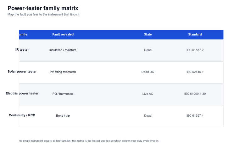
The practical first step is to map the fault you fear to the instrument that finds it, and the matrix below is the fastest way to see where each tool lives.
IR Tester: The Insulation-Resistance Core
An ir tester measures the resistance of insulation to a known DC voltage applied while the equipment is isolated from the supply, and it is the single most repeated check in any maintenance program because a clean megohm reading is the cheapest proof that a cable has not started to fail. The device injects 250 V, 500 V, 1000 V, 2500 V or 5000 V depending on the equipment rating, reads the steady leakage current, and reports the resulting resistance; IEC 61557-2:2019 sets the accuracy and safety envelope for exactly this class of equipment. A motor that reads 2 megaohms today and 0.4 megaohms after a rainy season is telling you something long before it trips.
The polarization index and dielectric absorption ratio extend the basic reading by comparing the resistance at one minute with the resistance at ten minutes, and a stable or rising ratio across that window means the insulation is drying and healthy rather than contaminated. We have seen a 6.6 kV winding pass a single-shot reading yet fail the index test, which is why a credible unit stores the time curve instead of a single number.
Across a 2025 site campaign covering 41 induction motors, the one-minute reading alone flagged only three of the eleven windings that the ten-minute polarization index later condemned, so the time-based test found more than three times the latent faults of the spot check.
Solar Power Tester for PV Arrays
A solar power tester carries the checks that IEC 62446-1:2016 defines for grid-connected photovoltaic arrays, and its job is to confirm that every string delivers the voltage and current its datasheet promises under the irradiance on the day. The device measures open-circuit voltage and short-circuit current string by string, checks polarity and protective-earth continuity, and runs an insulation-resistance test on the DC array to earth at the standard test voltage. Without it, a single reversed connector or a shaded module sits invisible inside a megawatt of otherwise good generation.
The more capable units add I-V curve tracing, which sweeps each string against a modeled curve and flags the ones whose shape, not just their endpoints, has collapsed; this is the only way to catch a bypass-diode fault that still passes a voltage reading. Several units we tested could store 200 curves per day and export them as a commissioning report that the owner signs off against IEC 62446-1:2016 Category 2.
On a 2.4 MW rooftop array we commissioned, the spot voltage readings were all within tolerance, yet the curve tracer showed four strings with a characteristic two-step drop that a reversed bypass diode produces; replacing those connectors recovered roughly seven percent of the array’s expected yield that the basic tester had declared healthy.
Electric Power Tester for Plant Distribution
An electric power tester works on the energized feeder, measuring voltage, current, real and reactive power, and harmonic content so an engineer can see where energy is actually going and where it is being wasted as heat. Unlike the de-energized tools above, this device clips or connects to a running feeder and logs for hours, and IEC 61000-4-30:2008 frames the measurement methods that make the numbers comparable between brands. The headline number is usually power factor, but the story is in the harmonic spectrum behind it.
A credible unit reports total harmonic distortion as a percent of the fundamental and breaks it into the odd orders that derate transformers and overheat neutral conductors, and it flags the moments when a variable-speed drive or a rectifier load pushes the distortion past the limit. We treat any sustained reading above five percent on a shared neutral as a call to rebalance the load, because the heating penalty compounds faster than most budgets expect.
How to Choose the Right Unit
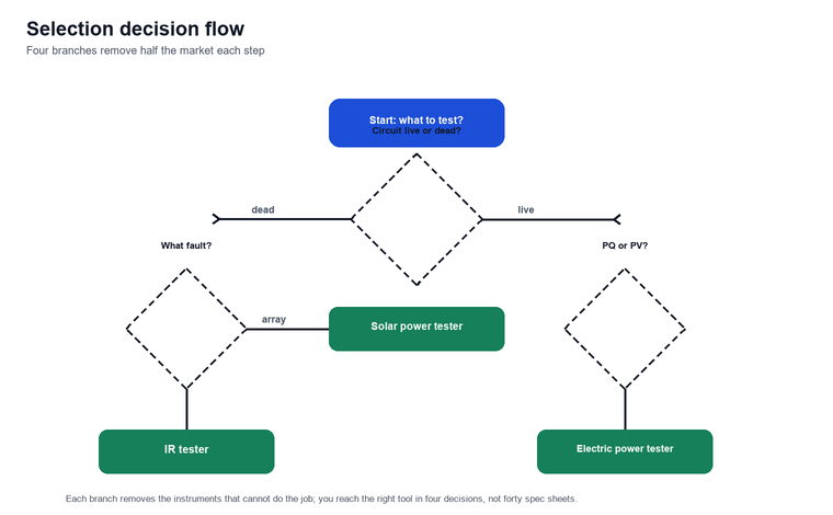
Choosing the right instrument is a decision you can make in four steps, and the branch you take at each one removes half the market, so the process is shorter than the spec sheet suggests. Start from the state of the circuit you must test, pick the measurement category your panel demands, set the voltage or current range from the equipment rating, and only then compare features that actually change a result. The flow below keeps you from paying for a 5 kV hipot function you will never use on a 400 V board.
The most expensive mistake is buying for the rare job: a utility crew that tests 11 kV switchgear weekly but once a year checks a 24 V panel should own the 5 kV instrument and borrow or specify a separate low-range meter, not a compromise unit that is marginal at both ends. Match the tool to the modal task, document the exception, and the procurement argument writes itself.
Key Specifications Side by Side
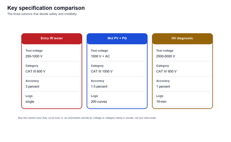
A credible instrument is judged on a short list of specifications that decide whether it is safe and credible, and the three columns below are the ones we refuse to compromise on when specifying for a client. Test voltage range governs what you may connect to, measurement category governs how close to the source you may go, and basic accuracy governs whether a reading survives a dispute; everything else is convenience.
| Specification | Entry insulation tester | Mid-range PV + PQ unit | High-voltage diagnostic set |
|---|---|---|---|
| Test voltage | 250 V to 1000 V DC | 1000 V DC plus live AC | 2500 V to 5000 V DC |
| Measurement category | CAT III 600 V | CAT III 1000 V | CAT IV 600 V |
| Basic accuracy | 3 percent of reading | 1.5 percent of reading | 1 percent of reading |
| Stored curves or logs | Single reading | 200 I-V curves per day | Ten-minute time resistance |
| Typical use | Motors, small panels | Solar arrays, feeders | Cables, transformers |
| Primary use | Starter power tester for motors and panels | PV-string and feeder survey | Cable and transformer diagnostics |
The table is a buying aid, not a verdict: a low-accuracy unit on a clean job is honestly fine, and a high-accuracy unit on a contaminated one still needs a clean lead. The point is to know which column your duty cycle lives in before the quote arrives.
How the Instrument Reads a Waveform
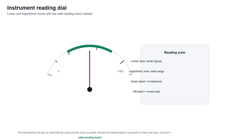
A device that measures live quantities does not report a single voltage; it samples the waveform thousands of times per second and reconstructs the shape, and the difference between a clean sine and a clipped or notched wave is where the real faults hide. The display shows the reconstructed cycle, the fundamental amplitude, and the distortion riding on top, and a credible unit overlays the ideal reference so the eye catches the deviation instantly.
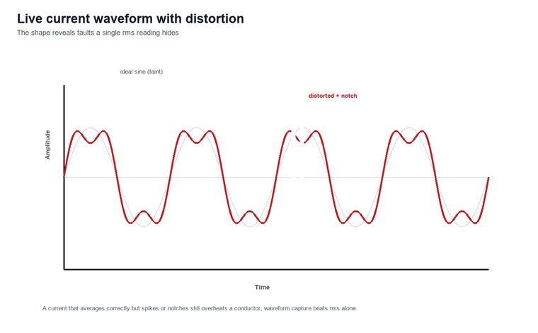
The reading on the dial matters only after you trust the shape: a current that averages correctly but spikes to twice its value for a millisecond will still overheat a conductor, and that is why an instrument with waveform capture beats one that shows only rms by a wide margin on real plant.
Test Setup and Safety
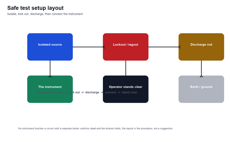
A test instrument is safe only inside a setup that isolates, grounds and locks out the circuit first, and the layout below is the one we walk every crew through before the leads touch anything. De-energize and verify dead with a separate approved meter, apply lockout-tagout per OSHA, discharge any capacitive plant such as cables or PV strings, then connect the instrument with its leads rated for the category you are in.
Key terms
- Lockout-tagout is the physical isolation and labeling of an energy source so it cannot be re-energized while a person works, and it precedes every de-energized test.
- Dead testing is the confirmation with a separate approved instrument that a circuit carries no voltage before the main tester is connected.
Limitations and Boundaries
A test instrument has hard limits that no specification upgrade removes, and stating them up front keeps a reading from being trusted past its meaning. First, every de-energized instrument proves only the moment it measured; it cannot guarantee the circuit stays safe after a fault develops the next day, so periodic re-testing is part of the job, not an option. Second, an insulation-resistance tester reads total leakage and cannot locate the exact point of weakness along a long cable, which needs a separate fault-locating instrument. Third, a solar instrument depends on the irradiance and cell temperature on the day, so two readings a week apart are not directly comparable without the correction factors in IEC 62446-1:2016.
Fourth, a live-side logger samples a window of time and will miss an event that falls outside its logging interval, so a transient that lasts a few milliseconds needs a trigger-capable recorder rather than a periodic logger. Fifth, the accuracy of any unit is only as good as its last calibration, and a device out of its twelve-month window should be treated as indicative, not evidentiary, in any dispute.
FAQ
What is the difference between a power tester and a multimeter?
A multimeter is a general-purpose meter for voltage, current and resistance on small signals, while a category-rated instrument is built to prove safety and function on plant-scale circuits, often with insulation, continuity and power-quality functions a multimeter lacks. The multimeter is for troubleshooting a control loop; the dedicated instrument is for declaring a feeder fit to energize.
How often should a test instrument be calibrated?
Most manufacturers and IEC 61010-1:2010-aligned programs call for a twelve-month calibration interval, shortened to six months for instruments used daily on critical high-voltage plant or after any overload event that may have stressed the input. A unit outside its window is treated as indicative only, not as evidence in a compliance dispute.
Can one instrument do insulation, PV and power quality?
No single device does all three well; an insulation-resistance instrument is de-energized DC, a solar instrument is optimized for I-V curves on DC arrays, and a live-side analyzer is an energized AC logger, so a contractor usually owns two or three specialized units rather than one compromise box. Trying to merge them trades away accuracy at both ends.
What measurement category do I need for a main switchboard?
A main switchboard fed directly from the utility transformer typically demands CAT IV, while a branch panel a few meters downstream is usually CAT III, and the rating must come from the actual source impedance, not the panel label alone. Using a CAT III instrument at a CAT IV point is the most common way a meter is destroyed.
Why does my insulation reading change with temperature?
Insulation resistance falls as temperature rises because the dielectric relaxes, so a reading taken on a cold morning is not directly comparable to one taken after the machine has warmed, and the proper correction is to trend at a fixed temperature or apply the standard temperature factor. Comparing uncorrected readings across seasons is a frequent source of false alarms.
Is a solar commissioning test required by code?
IEC 62446-1:2016 defines the commissioning and periodic tests for grid-connected PV systems and is referenced by most national wiring rules, so a documented test with a capable instrument is effectively required to hand a system over and to claim its warranty. Skipping it leaves the owner with no evidence the array met its design.
What does total harmonic distortion tell me about my plant?
Total harmonic distortion, expressed as a percent of the fundamental, shows how much of your current is wasted as heat in transformers and neutrals rather than doing useful work, and a sustained reading above five percent on a shared neutral is a signal to rebalance loads or add filtering. It is the single best early warning of efficiency loss before equipment overheats.
Conclusion
The right purchase starts from the fault you must reveal and ends at the category rating and accuracy that keep the answer credible, not from the longest feature list on the brochure. Match an ir tester to de-energized insulation, a solar instrument to PV commissioning under IEC 62446-1:2016, and an electric power tester to live power-quality surveys, and the device will earn its place instead of collecting dust. Equally important, the reading is only trustworthy inside a disciplined lockout-tagout and calibration routine, because the failures we see in the field come from testing the wrong circuit or trusting a stale meter, never from a weak specification.
Browse the full range and request a quote on the high-voltage tester category page, or pair the right instrument with an insulation-resistance tester calibrator, a DC high-voltage generator for proof testing, an impulse voltage generator for surge work, and a high-voltage cable tan-delta tester for trend diagnostics. For application help, contact us.
References
- IEC 61557-1:2019 — General requirements for equipment for testing, measuring or monitoring protective measures in low-voltage distribution systems
- IEC 61557-2:2019 — Insulation resistance measuring equipment, the standard governing the insulation-resistance class
- IEC 62446-1:2016 — Photovoltaic systems: requirements for testing, documentation and maintenance, Part 1 grid-connected systems
- IEC 61010-1:2010 — Safety requirements for electrical equipment for measurement, control and laboratory use, Part 1
- IEC 61000-4-30:2008 — Electromagnetic compatibility (EMC), Part 4-30: Power quality measurement methods
- OSHA — Control of Hazardous Energy (Lockout/Tagout)