

Author: Leon Zhang — Power monitoring and testing equipment team, Baoding Houfeng Trading Co., Ltd., specifying power monitoring and high-voltage test equipment for substations, utilities and industrial plants
Technical review: this guide passed editorial review and was checked against IEC 61010-2-032:2023, IEC 61000-4-7:2002+A1:2008, IEC 61000-4-30:2025, IEEE 1459-2025 and IEEE 519-2022 before publication
Last updated: 24 October 2026
Multimeter with true rms: Selection Guide, Key Specifications and Test Setup
A multimeter with true rms is the only kind worth carrying onto a site where the loads are not resistors, because the number it shows is the one that decides whether a drive output, a dimmed lighting circuit or a switch-mode supply is inside tolerance — and the cheaper alternative, an average-responding meter, is quietly wrong by tens of percent exactly where the waveform is worst. This guide sets out what the true-RMS claim actually promises, how the converter inside the instrument is built, what else has to appear on the specification sheet before the claim means anything on a real panel, how to choose between a hand-held meter and a clamp when the measurement is current, and how to prove the whole chain against a known source before the reading is allowed to drive a decision. It is written for the engineer specifying instruments for a team and for the technician who has just been handed one and told to find out why a motor keeps tripping.
Key Takeaways
- True RMS reports the heating value of a waveform — the square root of the mean of the squared instantaneous values — while an average-responding meter rectifies, averages and multiplies by a fixed 1.1107, a constant that is only correct for a pure sine (IEEE 1459-2025).
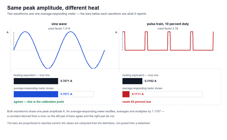
- The error is not small where it matters: on an ideal pulse train with a crest factor of 3.16, an average-responding meter reads about 65 percent low, and the sign of the error follows the waveform shape rather than the crest factor alone .
- Crest factor is the number that limits the meter rather than the one that rescues the reading: most hand-held instruments specify AC accuracy only up to a crest factor of about 3 at the top of the range, and say nothing about behaviour above it.
- A digital true rms multimeter computes RMS from samples, so the sample rate decides the highest harmonic the instrument can see at all — a meter sampling at 12.8 kHz resolves the 63rd harmonic of a 50 Hz fundamental and nothing above it.
- The label on the box is only half of the specification: AC bandwidth, minimum frequency, crest-factor limit, whether the DC component is included and the AC-band accuracy formula decide whether a reading is defensible, and the safety rating decides whether the operator survives taking it (IEC 61010-2-032:2023).
- Proving the instrument takes three steps and about three minutes, and it follows the same discipline as proving a circuit dead: a known source, the measurement, then the known source again.
What True RMS Actually Measures
The root-mean-square value of a waveform is the direct current that would deposit the same heat in the same resistor over the same interval, which is why it is the only value that can be compared directly with the thermal rating of a conductor, a fuse or a transformer winding.
True RMS is computed by taking the instantaneous value of the waveform, squaring it so that the negative half-cycle contributes the same as the positive one, averaging the squared values over a whole number of cycles, and taking the square root of the result. For a sine of peak amplitude A the answer is 0.7071 A, and this is the value every nameplate, every cable table and every breaker curve assumes.
An average-responding meter never computes that. Average-responding refers to a design that rectifies the waveform, averages the absolute value and multiplies by a constant. For a sine the mean of the absolute value is 0.6366 A, and the ratio between the RMS value and that mean is π divided by two times the square root of two, which is 1.1107. The meter bakes 1.1107 into its scale, so it reads a sine exactly right and every other waveform wrong by whatever the shape of that waveform contributes.
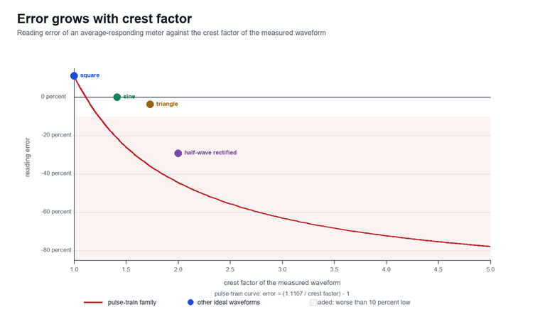
Crest factor is the ratio between the peak of a waveform and its RMS value, and it is the number that decides whether a meter stays inside its own accuracy specification. The consequence is a table worth keeping in the toolbox, because it is computed from the definitions rather than quoted from a datasheet :
| Waveform (peak amplitude A) | Crest factor | True RMS value | What an average-responding meter shows | Error of the average-responding meter against a multimeter with true rms |
|---|---|---|---|---|
| Sine | 1.414 | 0.7071 A | 0.7071 A | none — this is the calibration point |
| Triangle | 1.732 | 0.5774 A | 0.5554 A | 3.8 percent low |
| Square | 1.000 | 1.0000 A | 1.1107 A | 11.1 percent high |
| Half-wave rectified sine | 2.000 | 0.5000 A | 0.3536 A | 29.3 percent low |
| Pulse train, 25 percent duty | 2.000 | 0.5000 A | 0.2777 A | 44.5 percent low |
| Pulse train, 10 percent duty | 3.162 | 0.3162 A | 0.1111 A | 64.9 percent low |
Two rows of that table deserve a second look. The square wave reads eleven percent high rather than low, because a square wave spends all of its time at the peak and an average-responding meter has been calibrated to expect a sine that does not. And the two crest-factor-2 rows read twenty-nine percent low and forty-four percent low respectively, which is the clearest possible demonstration that crest factor alone does not predict the error: what the meter is really responding to is the ratio between the mean of the absolute value and the RMS value, and two waveforms can share a crest factor while differing in that ratio by more than half.
Why the Error Only Appears Where the Waveform Is Not a Sine
A site full of switch-mode supplies, dimmers, variable-speed drives and LED drivers is a site full of non-sinusoidal current, and that distortion is not a fault condition but the normal operating state of the load.
The standards that govern supply quality treat the distortion as an expected feature of the network rather than an anomaly. IEEE 519-2022 caps voltage distortion at 8% total harmonic distortion and 5% for any individual harmonic at a point of common coupling at or below 1 kV (IEEE 519-2022), and limits total demand distortion of current to 5% where the short-circuit ratio is below twenty. Those numbers are limits, not descriptions of a broken system, and they sit alongside an entire measurement standard — IEC 61000-4-7:2002+A1:2008 — written specifically to tell instrument builders how to measure harmonics and interharmonics up to 9 kHz on 50 Hz and 60 Hz systems (IEC 61000-4-7:2002+A1:2008).
That is the environment a true multimeter is bought for. The six-pulse rectifier at the input of a drive draws current in two humps per half cycle, a phase-angle dimmer clips the top off the voltage waveform, and a switch-mode supply takes its current in a narrow pulse near the peak of the voltage. None of those waveforms is rare, none of them is a fault, and all of them defeat a meter that assumes a sine.
| Load on a typical panel | Current waveform signature | Crest factor to expect | What an average-responding meter does |
|---|---|---|---|
| Switch-mode power supply | narrow pulse near the voltage peak | 2.5 to 4 | reads low, by a margin that grows with the pulse width |
| Six-pulse drive rectifier | two conduction humps per half cycle | 2 to 3 | reads low, and the error changes with load |
| Phase-angle dimmed lighting | clipped sine on the voltage side | 1.4 to 2 | reads low on the clipped part of the cycle |
| LED driver | pulse train with a flat top | 2 to 3 | reads low, and the reading moves with dimming level |
| Resistive heater, incandescent load | sine | 1.414 | correct — this is the only case where it is |
Total harmonic distortion is the root-sum-square of every harmonic component expressed as a share of the fundamental, and it is the figure that the distortion limits above are written against. What true RMS does not do is tell you which harmonic is responsible. A single RMS number is a summary, and two very different spectra can produce the same one. Where the question is why a transformer is running hot or why a neutral is overloaded, the instrument that answers it is a power quality analyser rather than a meter, and the power quality analyzer guide covers how those instruments separate the spectrum. A true-RMS meter tells you the total; the spectrum tells you the cause.
How a True RMS Converter Is Built, and Why It Matters
Three converter designs have been used to produce a genuine root-mean-square reading, and the one inside the instrument in your hand determines the bandwidth, the accuracy and the way it fails.
The oldest is the thermal converter. Two matched resistors are heated, one by the signal and one by a DC reference, and a servo adjusts the reference until the temperatures match; the reference current is then the RMS value of the signal. It is inherently true RMS because it measures the thing RMS is defined by — heat — and it remains the reference method in calibration laboratories, but it is slow, fragile and power-hungry, which rules it out of a hand-held meter.
The second is the analogue computing converter, which squares the signal with log and antilog circuits and averages the result. It is fast, works over a very wide bandwidth, and needs no sampling, but its accuracy drifts with temperature and it has largely disappeared from commercial instruments for that reason.
The third, and the one in almost every instrument sold today, is the digital sampling converter. An analogue-to-digital converter samples the waveform, the processor sums the squares of the samples over a window and takes the root of the mean, and the result is a true RMS value by direct computation. The three designs are not equivalent in what they can be asked to do:
| Converter design | How it produces RMS | Typical bandwidth | Where it is found today |
|---|---|---|---|
| Thermal | heats a matched resistor and servos a DC reference to the same temperature | DC to low megahertz, limited by the heater’s thermal time constant | calibration laboratories, reference standards |
| Analogue computing | squares the signal with log and antilog circuits, then averages | wide, set by the squaring circuit | largely superseded; specialist wideband instruments |
| Digital sampling | converts the waveform to samples, sums the squares over a window, takes the root of the mean | set by the sample rate; the Nyquist limit is half of it | every hand-held meter and clamp sold now |
This design has three consequences that never appear on the front of the box :
- The window has to contain a whole number of cycles. A window that stops mid-cycle leaves a partial cycle in the average and the reading flickers or biases low; well-designed instruments synchronise the window to the measured frequency and say nothing about it.
- The sample rate sets the highest harmonic that exists. A converter sampling at 12.8 kHz cannot report a component above 6.4 kHz, so a meter with that rate resolves the 63rd harmonic of a 50 Hz fundamental and is blind above it — which is exactly the boundary IEC 61000-4-7:2002+A1:2008 draws when it stops counting harmonics at 9 kHz.
- A DC component either counts or does not, depending on the input coupling. A true-RMS converter fed through an AC-coupled input reports the RMS of the AC part only, which is the correct answer for a ripple measurement on a DC bus and the wrong answer for the heating value of the bus itself.
The practical failure mode, therefore, is not a wrong constant — that failure belongs to average-responding meters — but a bandwidth that silently excludes the very components that made the measurement worth taking. A meter specified to 400 Hz will report a confident, stable, true-RMS number for a drive output whose switching ripple sits at several kilohertz, and the number will be correct about a signal that is not the one on the terminals. Instruments built for that work state their sampling rate openly: the HF-PQ-204 portable power quality meter, for example, uses a 16-bit converter sampling at 12.8 kHz, which is what allows it to report harmonics from the 2nd to the 63rd within the IEC 61000-4-30:2025 Class A framework.
What a Multimeter with True RMS Has to Specify Besides the RMS Claim
A true multimeter earns its name from the converter, but it earns its place in the toolbox on six other lines of the specification sheet, and most of those lines are missing from the front of the box.
Read the datasheet for these, in this order, and ignore the marketing word until all six are answered:
| Specification line | What to look for | Why it decides whether the reading is usable |
|---|---|---|
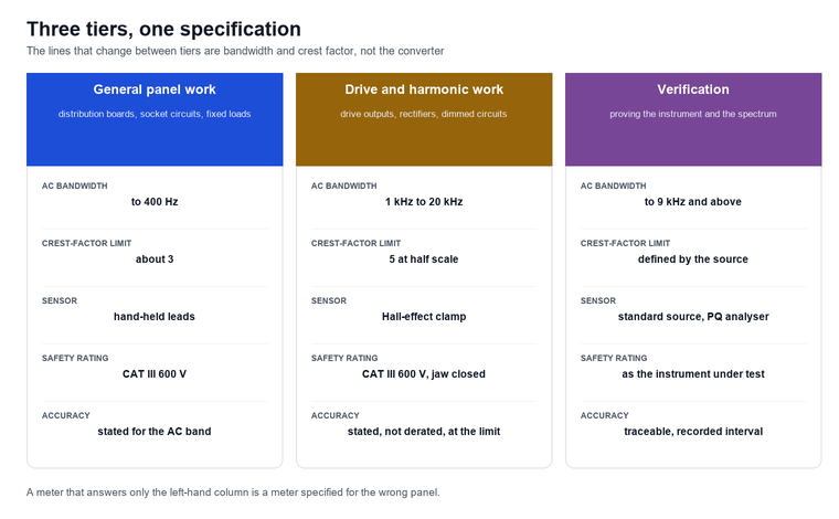
| AC bandwidth, upper limit | 400 Hz for general panel work; 1 kHz to 20 kHz where drive outputs are measured | harmonics above the bandwidth are not measured, they are excluded |
| AC bandwidth, lower limit | 40 to 45 Hz is typical | below the stated limit the accuracy is unspecified, and a 25 Hz excitation reads as something |
| Crest-factor limit | about 3 at full scale, sometimes 5 at half scale | above the limit the accuracy derates or is not stated at all |
| AC accuracy formula | stated as percent of reading plus counts, in the AC band specifically | the AC band is always looser than the DC band, and the difference is the converter’s error |
| DC component handling | whether the converter is AC-coupled or includes the DC term | decides whether the reading is the ripple or the heating value of the whole bus |
| Safety rating | IEC 61010-2-033:2023 for meters, IEC 61010-2-032:2023 for clamps | an accurate reading from an input stage that was never rated for the panel is not a result |
The last line is the one that gets skipped. A true-RMS converter does nothing for the transient that arrives with the measurement, and the safety standard for hand-held current clamps — IEC 61010-2-032:2023, edition 5.0, published 20 September 2023 — is what defines the input stage, the clearances and the marking that stand between the clamp and the arc (IEC 61010-2-032:2023). The measurement category and the working voltage printed beside the jaws belong to that standard, and they apply to a clamp meter exactly as they apply to a hand-held meter: the converter is downstream of the protection, not a substitute for it.
Choosing a True RMS Digital Clamp Meter
When the measurement is current on a live panel, a true rms digital clamp meter replaces a shutdown with a jaw and a display, and the choice turns on the sensor, the jaw and the crest-factor rating rather than on the converter alone.
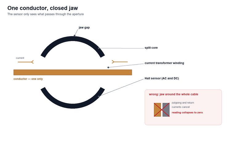
Three sensor designs are in common use, and they are not interchangeable. A current-transformer jaw needs a changing flux to produce its output, so it measures AC only, and it saturates if a large DC component is present. A Hall-effect jaw measures the field directly and therefore works on AC and DC, at the cost of a supply, a zero adjustment and a small offset that drifts. A Rogowski coil is an air-cored winding that outputs the rate of change of current, which gives it no saturation limit and a wide bandwidth but no DC response and an integration stage that has to be trusted.
| Sensor type | Measures | Saturation behaviour | What it costs you |
|---|---|---|---|
| Current transformer | AC only — needs a changing flux | saturates on a large DC component | simple, cheap, no zero adjustment |
| Hall effect | AC and DC, by measuring the field directly | no core to saturate | needs a supply and a zero adjustment that drifts |
| Rogowski coil | AC only, output proportional to the rate of change | no core, so no saturation limit | an integration stage to trust, and no DC response |
Three practical points decide more clamp selections than the accuracy figure ever does. The jaw has to close completely around one conductor — never around a whole cable, where the outgoing and return currents cancel and the reading collapses toward zero. The jaw diameter has to suit the conductor, because a busbar that fills only a third of the aperture gives a reading that depends on where inside the jaw it sits. And inrush or peak-hold has to be present in firmware rather than bolted on afterwards, because a motor start is over long before a min-max function can be read.
For periodic verification, the instrument that does the job is a standard source rather than a second opinion. The HF-MT-507 clamp meter calibrator outputs AC and DC current over three clamp-calibration ranges from 0 to 2 000 A with AC output indicated as a true-RMS value, distortion below 0.5 percent and ripple factor below 0.5 percent, at an AC accuracy of ±(0.05 percent of reading + 0.03 percent of full scale) and a DC accuracy of ±(0.03 percent of reading + 0.02 percent of full scale). That combination — a defined true-RMS output with a stated distortion ceiling — is what makes it suitable for checking clamp meters and 4½-digit multimeters in the field rather than only in a laboratory.
Verifying the Claim on Site: Test Setup
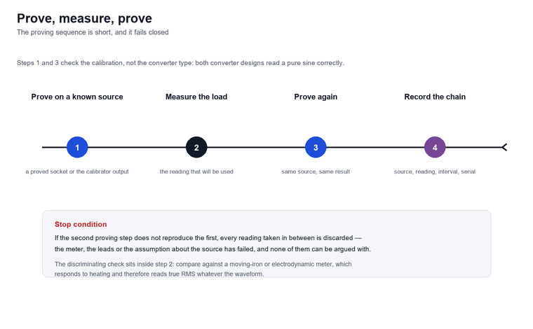
Proving the instrument takes three steps and about three minutes, and it follows the same discipline as proving a circuit dead: a known source, the measurement, then the known source again.
The first step checks calibration but not the converter type. Put the meter on a proved live socket or on the output of a calibrator and confirm the reading; because both converter types read a pure sine correctly, this step tells you the instrument is within its stated accuracy and tells you nothing about whether the RMS claim is genuine.
The second step is the discriminating one, and it needs a reference instrument that is inherently true RMS. A moving-iron or electrodynamic panel ammeter responds to the heating of the current it carries and therefore reads true RMS whatever the waveform, so measuring the same distorted load with one of those and with the meter under test separates the two converter types immediately: the average-responding meter reads low, by an amount that grows with crest factor, and the moving-iron meter does not . In the laboratory the same check is done with a calibrator that can output a defined non-sinusoidal waveform, or with a power quality analyser whose true-RMS and harmonic figures can be reconciled against each other.
The third step is consistency. Take three readings ten seconds apart on the same steady load: a true-RMS converter on a stable circuit should not wander by more than a count or two, and a reading that drifts is telling you either that the load is genuinely fluctuating or that the averaging window is too short for the frequency being measured.
Four details make the sequence repeatable rather than a one-off:
- Check the limits before the reading, not after. Confirm the crest factor and frequency of the expected waveform against the meter’s stated limits; a reading taken outside them is a number without an accuracy.
- Close the jaw properly, around one conductor. A jaw that does not fully close, or that has debris in the gap, loses flux and reads low, and it does so silently.
- Zero the DC current range with the jaw open and in the same orientation as the measurement, because Hall-effect offsets are position-dependent and a moving iron pointer hides an offset that a digital display does not.
- Record the proving steps with the reading. A reading that cannot be traced back to a proved source cannot be defended in a test record, which is the same traceability argument that governs calibration intervals.
Where the instrument is a clamp meter used for compliance work, the interval and the source both matter: an annual check against a source such as the HF-MT-507, with the result recorded against the clamp’s serial number, keeps the field readings inside the traceability chain that a calibration certificate is supposed to provide.
Choosing a Digital True RMS Multimeter
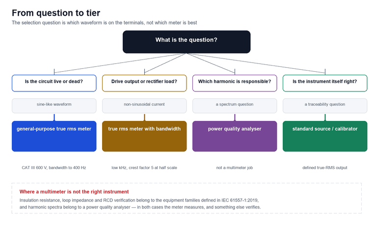
A digital true rms multimeter is the right default for industrial and commercial work, and the only decision left is which tier of the same specification your panels actually demand.
The general-purpose tier covers distribution boards, socket circuits and fixed loads: a 4 000-count display, CAT III 600 V, an AC bandwidth to 400 Hz and a crest-factor limit of 3 will cover almost every reading an electrician takes, because almost every waveform on that work is either a sine or close enough to one that the difference does not matter.
The drive and harmonic tier covers anything fed through an adjustable-speed drive, a soft starter or a large rectifier: a bandwidth into the low kilohertz, a crest-factor limit of 5 at half scale, a stated accuracy in the AC band rather than a single headline figure, and — for current — a Hall-effect clamp rather than a current-transformer jaw, because the DC component in a partially loaded drive bus is exactly what a transformer-core jaw cannot see.
The verification tier is not a better meter but a different instrument: a standard source for calibration and a power quality analyser for the spectrum. The HF-GT-208 frequency selective multimeter sits alongside it for measurements taken under heavy site interference, holding its accuracy within 5 percent under interference ten thousand times the power frequency by tracking and suppressing the interfering frequency between 40 Hz and 70 Hz, which is what makes grounding measurements possible in a live substation yard at all.
FAQ
What does true rms actually mean on a multimeter?
It means the instrument computes the square root of the mean of the squared instantaneous values over a whole number of cycles, which is the heating equivalent of the waveform. An average-responding meter instead rectifies, averages and multiplies by 1.1107, a constant derived from a sine, so it reads a sine correctly and other waveforms wrong.
Can I use a true rms multimeter to measure harmonics?
No. True RMS gives you one number for the whole waveform, and two very different spectra can produce the same number. Harmonics are separated by a power quality analyser or a spectrum analyser, following the measurement guidance in IEC 61000-4-7:2002+A1:2008, which defines how harmonics and interharmonics up to 9 kHz are measured and grouped.
Does a true rms meter read DC correctly?
The DC ranges read DC correctly on any meter. What varies is whether the AC ranges include a DC component: a true-RMS converter behind an AC-coupled input reports the RMS of the AC part only, so measuring a DC bus with ripple gives you the ripple and not the heating value of the bus. Check the input coupling on the datasheet if that distinction matters.
Why does my true rms meter disagree with the clamp meter?
Usually because the two instruments are seeing different things rather than because one is wrong. Check whether the clamp jaw closed fully, whether it is around one conductor rather than a whole cable, whether the clamp is a current-transformer design measuring a waveform with a DC component, and whether either instrument is being used outside its stated crest-factor or bandwidth limit.
What should I look for in a multimeter with true rms?
Four lines of the specification sheet, in this order: the AC bandwidth at both ends, the crest-factor limit and whether the accuracy is stated or derated at it, the accuracy formula written for the AC band specifically, and the safety rating for the category of panel it will be used on. A meter that answers those four questions is a true multimeter; one that only prints the words true rms on the box has answered none of them.
Is a true rms label on an inexpensive meter genuine?
Sometimes, and the only way to know is the discriminating test: compare it against a moving-iron or electrodynamic instrument, or against a calibrator, on a waveform known not to be a sine. A meter that reads a sine correctly has proved its calibration, not its converter, and the two are different claims.
What crest factor do I need for a variable-speed drive output?
Look for a stated crest-factor limit of 5 at half scale and an accuracy that is specified rather than derated at that point. Lightly loaded six-pulse rectifiers commonly present crest factors between 2 and 3, and a meter whose accuracy is only specified to a crest factor of 3 at full scale is already outside its own specification on that load.
How often should a true rms clamp meter be calibrated?
Follow the manufacturer’s interval, and shorten it after a drop, a jaw impact or exposure outside the stated environmental band. For clamps used on compliance work, an annual check against a defined source such as a clamp meter calibrator, recorded against the serial number, keeps the readings inside the traceability chain.
Limitations and Boundaries
A multimeter with true rms is a measuring instrument with a defined bandwidth, and knowing where that bandwidth ends is what separates a defensible reading from a confident one.
- It reports one number for the whole waveform. It cannot tell you which harmonic is present, which is a spectrum question and belongs to a power quality analyser.
- It is silent above its own bandwidth. A meter specified to 400 Hz excludes components above 400 Hz from its average, and it does not warn you that it has done so.
- Its accuracy is bounded by crest factor. Outside the stated crest-factor limit the accuracy derates or becomes unspecified, and the meter still displays a stable number.
- It cannot replace installation test equipment. Insulation resistance, loop impedance and RCD verification belong to the equipment families defined in IEC 61557-1:2019 and its companion parts, whose performance requirements are separate from the safety requirements that govern a meter.
- It cannot verify its own calibration. A proved source, a recorded interval and a traceable chain are what connect a field reading to a national standard, and no meter can supply those for itself.
Conclusion
A multimeter with true rms is specified on four things — the converter that earns the claim, the bandwidth and crest-factor limits that bound it, the accuracy formula stated in the AC band rather than on the front of the box, and the safety rating that decides whether the measurement can be taken at all. Get those four right and the reading takes care of itself; get the bandwidth wrong and nothing else on the specification sheet matters, because the instrument will confidently report a signal that is not the one on the terminals.
For the work a meter cannot do — the spectrum behind a heating problem, the insulation and earthing checks, the verification of the meter itself — the electrical test instruments category covers the dedicated equipment, including the HF-PQ-204 portable power quality meter for harmonic and distortion work to the 63rd order, the HF-MT-507 clamp meter calibrator for verifying clamp meters and 4½-digit multimeters against a defined true-RMS source, the HF-GT-208 frequency selective multimeter for measurements taken under heavy site interference, and the HF-GT-209 clamp ground resistance tester for earthing checks without auxiliary stakes. Where the question is cable condition rather than circuit state, the cable testing and monitoring programme is the next step beyond a handheld meter. If you are selecting instruments for a team and want the bandwidth and crest-factor limits checked against the panels your crews actually work on, contact us — we would rather argue about the specification before the reading is taken than after the trip.
References and Technical Sources
- IEC, Safety requirements for electrical equipment for measurement, control, and laboratory use — Part 2-032: Particular requirements for hand-held and hand-manipulated current clamps for electrical measurement and test, IEC 61010-2-032:2023, edition 5.0, published 20 September 2023 — input stage, clearances and marking for current clamps. webstore.iec.ch
- IEC, Electromagnetic compatibility (EMC) — Part 4-7: Testing and measurement techniques — General guide on harmonics and interharmonics measurements and instrumentation, for power supply systems and equipment connected thereto, IEC 61000-4-7:2002+A1:2008, edition 2.1, published 28 October 2009 — measurement of harmonics and interharmonics up to 9 kHz on 50 Hz and 60 Hz systems. webstore.iec.ch
- IEC, Electromagnetic compatibility (EMC) — Part 4-30: Testing and measurement techniques — Power quality measurement methods, IEC 61000-4-30:2025, edition 4.0, published 24 October 2025 — Class A and Class S measurement methods for power quality parameters. webstore.iec.ch
- IEEE, IEEE Standard Definitions for the Measurement of Electric Power Quantities Under Sinusoidal, Nonsinusoidal, Balanced, or Unbalanced Conditions, IEEE 1459-2025, published 16 May 2025, superseding IEEE 1459-2010 — definitions of RMS and related quantities under non-sinusoidal conditions. standards.ieee.org
- IEEE, IEEE Standard for Harmonic Control in Electric Power Systems, IEEE 519-2022, published 5 August 2022, superseding IEEE 519-2014 — voltage and current distortion limits at the point of common coupling. standards.ieee.org
- Baoding Houfeng Trading Co., Ltd., HF-MT-507 clamp meter calibrator technical specifications — AC and DC output ranges, accuracy, distortion and ripple figures. monitor-test.com