Leave your message

-
Leon Zhang sales consultant
-
Email: zxl635973785@gmail.com
-
Phone/WhatsApp/Wechat: +86 13655813266

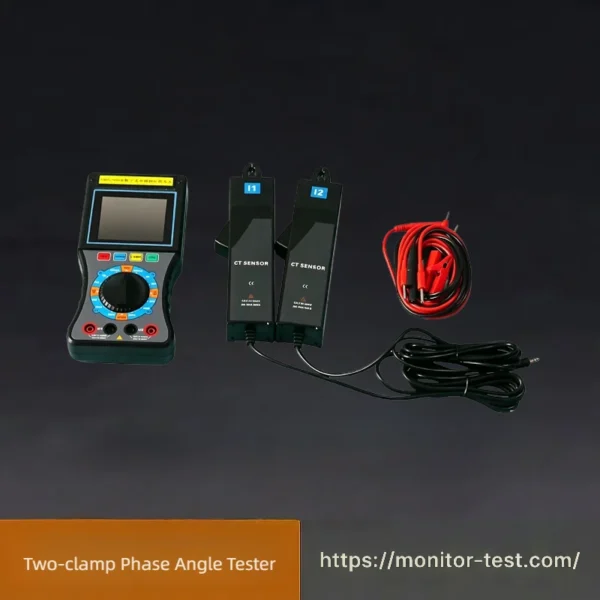
HF-RT-209 Two-clamp Phase Angle Tester
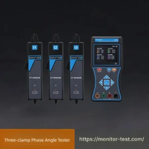
This two-clamp phase angle tester is designed for three-phase power commissioning. It accurately tests phase angle, phase sequence, voltage and current without disconnecting wires, widely used in substation wiring check and power circuit troubleshooting.
Send your requirements, we will quote for you within 12 hours
This portable two-clamp phase angle tester is specialized for three-phase power system inspection and wiring verification. Equipped with dual independent clamp CT sensors, it enables live current measurement without cutting off power lines. Fully isolated dual input channels eliminate short-circuit risks from wrong wiring. Featuring a large high-contrast LCD display and robust insulated casing, it precisely measures phase angle, phase sequence, voltage and current, ideal for substation commissioning, power circuit troubleshooting and electrical acceptance testing.
Product Features
● It adopts clamp-on current transformers for current input, so no need to disconnect the tested circuit during measurement.
● Fully insulated isolation is designed between the two input channels when measuring the phase difference between U1 and U2, completely preventing circuit short-circuits and instrument burnout caused by incorrect wiring.
● Equipped with a high-contrast LCD screen with 25 mm large characters, delivering excellent viewing experience.
● The housing is made of insulated engineering plastic, ensuring high safety and reliable performance.
Technical Parameters
Basic Error Limits
AC Voltage (See Table 1)
Table 1: AC Voltage Measurement Errors
| Range | Resolution | Basic Error Limit |
|---|---|---|
| 20 V | 0.01 V | ±(0.3% reading + 0.2% full scale) |
| 200 V | 0.1 V | |
| 500 V | 1 V |
Input Impedance: 2 MΩ for all ranges; Input impedance of voltage terminals ≥ 500 kΩ during phase measurement.
AC Current (See Table 2)
Table 2: AC Current Measurement Errors
| Range | Resolution | Basic Error Limit |
|---|---|---|
| 200 mA | 0.1 mA | ±(0.3% reading + 0.2% full scale) |
| 2 A | 1 mA | |
| 10 A | 10 mA |
Phase Measurement (U-U, U-I, I-I, See Table 3)
Table 3: Power Frequency Phase Measurement Errors
| Measuring Range | Resolution | Basic Error Limit |
|---|---|---|
| 0 ~ 360° | 1° | ±2° |
Operating Errors
| Category | Parameter | Value |
|---|---|---|
| Rated Operating Conditions | Ambient Temperature | (0 ~ 40) °C |
| Ambient Humidity | (20 ~ 80) % RH | |
| Measured Signal Waveform | Sine wave, β=0.05 | |
| Measured Signal Frequency | (50±0.5) Hz | |
| Position of measured conductor inside clamp jaw | Arbitrary | |
| Amplitude Range of Measured Signals for Phase Test | Phase measurement between U1-U2 | 30V ~ 500V |
| Phase measurement between I1-I2 | 10mA ~ 10.00A | |
| Phase measurement for U1-I2 / I1-U2 | 10V ~ 500V, 10mA ~ 10.00A | |
| External power frequency electromagnetic interference | To be avoided | |
| Rated Operating Error Limit | Under specified rated working conditions, the operating error limit for each measurement shall not exceed twice the corresponding basic error limit. |
Safety Characteristics
| Item | Specification |
|---|---|
| Withstand Voltage | The device can withstand 1000V/50Hz sinusoidal AC voltage for 1 minute between voltage input terminals & casing, and between clamp CT iron core/clamp jaw & internal windings; 500V/50Hz sinusoidal AC voltage for 1 minute between two voltage input terminals. |
| Insulation Resistance | ≥ 10 MΩ between internal circuits and casing, and between two voltage input terminals. |
Purpose & Applications
This two-clamp phase angle tester is widely applied in three-phase power distribution systems. It is used to check phase sequence, verify wiring correctness, measure phase difference between voltage and current, inspect CT polarity, and troubleshoot circuit faults for substations, power plants and electrical engineering acceptance projects.
FAQ for Two-clamp Phase Angle Tester
Q1: What core parameters can this two-clamp phase angle tester measure?
A: It can test phase angle, phase sequence, AC voltage, AC current, and phase difference between voltage & current, covering all common measurement demands for three-phase power circuits.
Q2: Is power cut-off required before conducting measurement?
A: No need. Equipped with dual clamp CT sensors, it clamps on live wires directly without disconnecting the tested circuit, supporting live-line safe measurement.
Q3: Why dual fully insulated input channels are designed?
A: Complete isolation between two loops avoids short circuits and instrument burnout caused by miswiring, greatly improving operation safety for field electricians.
Q4: What is the measurement range & accuracy of phase angle?
A: Phase measuring range: 0~360°, resolution 1°, basic accuracy ±2°, fully compliant with power frequency on-site testing standards.
Q5: Can it check the polarity of current transformers (CT)?
A: Yes. It is commonly used to verify CT wiring polarity, inspect secondary loop wiring correctness in substations and distribution cabinets.
Q6: What working environment does the tester adapt to?
A: Rated working temperature: 0~40℃, humidity 20%~80%RH; it works stably under standard 50Hz power frequency sine wave signals.
Q7: Does the device comply with electrical safety standards?
A: It features high insulation resistance and qualified withstand voltage test. The insulated engineering plastic shell effectively guards users against electric shock hazards.
Q8: What scenarios is this instrument mainly used for?
A: Widely used in substation commissioning, power engineering acceptance, three-phase wiring checking, power circuit troubleshooting and industrial electrical maintenance.
Reviews
There are no reviews yet.