


Compliance with IEC 60270 for transformer PD monitoring requires more than using an IEC 60270-compatible PD detector. The complete measurement setup—including the test circuit, measuring system, calibration, background-noise control, measurement procedure, and recording of results—must be properly configured and verified. For EPC contractors, utility asset teams, and third-party testing laboratories, consistent IEC 60270 partial discharge compliance ensures all transformer PD measurement data is repeatable, auditable, and comparable across factory acceptance tests (FAT), site acceptance tests (SAT), and long-term diagnostic monitoring. This guide breaks down end-to-end IEC 60270 PD measurement workflows based on the latest 2025 standard edition.
This article titled How to Comply with IEC 60270 for Transformer PD Monitoring elaborates on how transformer partial discharge monitoring complies with IEC 60270. It helps engineers standardize partial discharge calibration, noise suppression and apparent charge detection procedures, obtain reliable monitoring data, accurately evaluate transformer insulation conditions and promptly identify potential insulation defects.

What Does IEC 60270 Cover in Transformer PD Measurement?
Published in June 2025, IEC 60270:2025 (4th edition) fully replaces the 2000 third edition and its 2015 amendment, serving as the global authoritative standard for charge-based partial discharge testing on high-voltage electrical equipment including power transformers. Unlike outdated versions, the 2025 update refines core technical rules and unifies measurement logic for both AC and DC test scenarios, forming the exclusive compliance basis for modern IEC 60270 partial discharge measurement.
IEC 60270 and Charge-Based Partial Discharge Measurement
A core revision of IEC 60270:2025 is its explicit focus on charge-based partial discharge measurement. The standard abandons ambiguous indirect detection metrics and uniformly defines apparent charge (measured in picocoulombs, pC) as the primary quantitative indicator for PD activity. This unifies data calibration and evaluation logic for all transformer PD tests worldwide.
What Are the Main IEC 60270 Requirements for Transformer PD Monitoring?
Full IEC 60270 requirements cover the entire PD measurement chain, from hardware configuration to result recording. The following table summarizes all mandatory verification items for compliant transformer partial discharge measurement, covering core specifications of IEC 60270:2025.
| IEC 60270 Consideration | What Needs to Be Verified |
|---|---|
| Test circuit | Suitable circuit configuration matching transformer test conditions, compliant with 2025 edition circuit specifications |
| Measuring system | Appropriate PD measuring system supporting analog and digital charge-based detection |
| Apparent charge | Accurate measurement and linear scaling of apparent charge values in pC |
| Calibration | Full calibration of the complete end-to-end measurement circuit per updated Annex A rules |
| Measurement bandwidth | Frequency response matching test requirements, avoiding integration and superposition errors |
| Background noise | Stable noise floor controlled, measured, and recorded before formal testing |
| Test voltage | Accurate monitoring and documentation of AC (≤500 Hz) or DC test voltage parameters |
| PD detection | Reliable identification of valid PD signals above noise threshold, excluding external interference |
| Data recording | Complete, standardized recording of all measurement parameters and raw data |
IEC 60270 Test Circuit Requirements
Test circuits and measuring systems are defined as core normative chapters in IEC 60270:2025. The standard mandates that transformer PD test circuits must form a complete, shielded, calibrated signal acquisition chain with no missing links or non-compliant components. All circuit configurations must adapt to AC (up to 500 Hz) and DC test scenarios, covering all conventional transformer voltage test conditions.
Mandatory circuit components include the test object (transformer under test), high-voltage coupling device, measuring impedance, shielded signal cables, and PD measuring instrument. Each component directly impacts signal fidelity and charge measurement accuracy, and all must meet the 2025 edition’s streamlined performance check standards for measurement system components.
How to Build an IEC 60270 Test Circuit for Transformer PD Measurement
A compliant IEC 60270 test circuit for transformer PD testing follows a fixed signal transmission architecture, ensuring consistent signal collection across all test scenarios. The standard circuit structure is: HV Source → Transformer Under Test → Coupling Device → Measuring Impedance → PD Detector. This end-to-end setup eliminates signal distortion, pulse superposition errors, and external signal crosstalk.
The high-voltage source provides standardized AC or DC test voltage; the transformer under test is the core test object where PD activity occurs; the coupling device extracts high-fidelity PD pulse signals from the high-voltage loop; measuring impedance filters and stabilizes signal amplitude; the PD detector performs charge-based data collection and calculation. All connection cables must be shielded, with standardized grounding to suppress ambient interference.
Coupling Device and Measuring Impedance
The coupling device (coupling capacitor/quadripole) is the core signal extraction component specified by IEC 60270:2025. It isolates high-voltage test voltage while coupling low-amplitude PD pulse signals into the measuring system, ensuring no high-voltage damage to testing instruments and complete capture of transient discharge pulses.
Measuring impedance matches the system bandwidth and signal attenuation characteristics. It stabilizes PD pulse waveform, reduces resonance and reflection interference in transformer winding and cable circuits, and ensures the output signal amplitude has a linear corresponding relationship with the actual apparent charge of PD. The 2025 edition optimizes impedance matching verification rules, simplifying performance checks while improving measurement stability.
PD Measuring Instrument
IEC 60270:2025 covers both analog and digital PD measuring instruments, with updated performance requirements for digital devices to adapt to modern data diagnosis needs. Qualified instruments must support direct apparent charge measurement (pC scale), accurate pulse repetition rate statistics, and phase-resolved PD (PRPD) pattern acquisition.
Key instrument compliance indicators include pulse resolution time, dead time control, and bandwidth response consistency. The instrument must avoid pulse pile-up superposition errors during high-frequency PD activity and ensure accurate capture of single pulse charge amplitude and polarity. All digital data processing functions must comply with Annex E normative guidelines.
Selecting the Measurement Frequency Range
Measurement frequency range directly determines test sensitivity and anti-interference capability, and must be matched to the overall test circuit performance. IEC 60270:2025 clarifies that conventional transformer PD testing applies to AC frequencies up to 500 Hz, while high-frequency measurement scenarios need to refer to IEC TS 62478.
In actual testing, narrow-band systems effectively suppress fixed-frequency industrial noise, while wide-band systems capture more comprehensive PD pulse waveforms. Engineers must select bandwidth based on on-site noise conditions, ensuring the system’s frequency response avoids integration errors and guarantees accurate apparent charge calculation. Frequency selection must be documented in test reports for result traceability.
How to Calibrate a Transformer PD Measurement System According to IEC 60270
IEC 60270 calibration is the core link ensuring valid partial discharge measurement according to IEC 60270. The 2025 edition comprehensively upgrades Annex A (calibrator performance test specifications), optimizing calibration methods and verification standards to replace all old 2000 edition rules. Calibration targets the complete test circuit rather than individual instruments, eliminating system-level measurement errors.
Why Calibration Is Required
PD test results are not absolute readings—all apparent charge data depends on the scale factor of the complete measurement system. Differences in cable length, coupling device parameters, and on-site grounding conditions will change system signal attenuation characteristics. Without full-circuit calibration, pC readings will deviate severely, leading to non-repeatable test data and invalid cross-project comparisons.
IEC 60270:2025 mandates calibration to confirm system scale factor, correct integration errors, and verify that the measuring system meets minimum sensitivity requirements. Calibration records are mandatory audit documents for FAT/SAT and equipment acceptance.
How IEC 60270 Calibration Is Performed
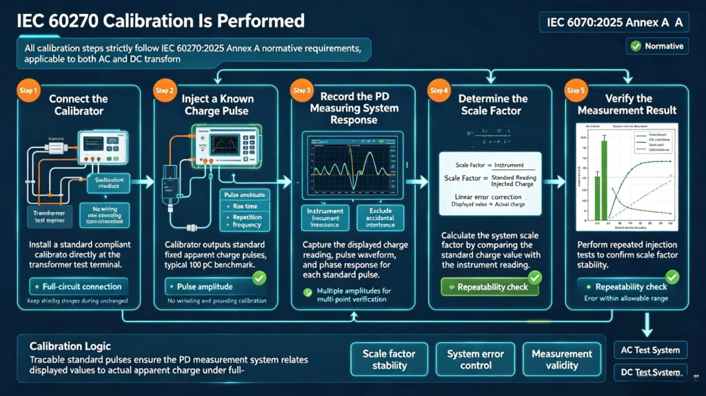
All calibration steps strictly follow IEC 60270:2025 Annex A normative requirements, applicable to both AC and DC transformer PD test systems:
Step 1 — Connect the calibrator Install a standard compliant calibrator directly at the transformer test terminal, completing full-circuit connection consistent with formal test conditions. No changes to circuit wiring, shielding, or grounding are allowed during calibration.
Step 2 — Inject a known charge pulse The calibrator outputs standard fixed apparent charge pulses (typical 100 pC benchmark), with pulse amplitude, rise time, and repetition frequency meeting 2025 edition performance test standards. Multiple groups of pulses with different amplitudes are injected for multi-point verification.
Step 3 — Record the PD measuring system response Capture the instrument’s displayed charge reading, pulse waveform, and phase response for each standard pulse. Record all raw data to exclude accidental interference impacts.
Step 4 — Determine the scale factor Calculate the system scale factor by comparing the standard injected charge value with the instrument reading. The system automatically or manually calibrates linear errors to ensure consistent proportionality between displayed values and actual charge.
Step 5 — Verify the measurement result Perform repeated injection tests to confirm scale factor stability. Ensure system error is within the standard allowable range, completing full-circuit calibration validation.
When Should the PD Measurement System Be Recalibrated?
IEC 60270:2025 specifies mandatory recalibration scenarios to maintain long-term measurement consistency: before testing new transformer test objects; after adjusting test circuit wiring, replacing cables or coupling devices; after instrument maintenance or component replacement; when on-site grounding or shielding conditions change significantly; and for batch repeated tests of the same equipment type at regular intervals.
Daily performance checks and periodic full calibration must be recorded in detail to form complete equipment performance files, complying with the standard’s system characteristic maintenance requirements.
How to Control Background Noise During IEC 60270 PD Measurement
External interference and background noise are the primary causes of invalid transformer partial discharge measurement data. IEC 60270:2025 adds detailed disturbance identification and suppression guidelines, helping engineers distinguish valid PD signals from ambient noise to ensure test result credibility.
Identify Background Noise Before the PD Test
Before applying high-voltage test power, measure and record the system noise floor. Background noise includes internal instrument thermal noise and external environmental interference (motor operation, broadcast signals, power electronic equipment switching pulses). The standard requires clear noise level records to define the minimum detectable PD magnitude of the system.
All noise sources must be classified and recorded, providing a baseline for subsequent PD signal judgment and interference elimination.
Reduce External Interference
Core noise suppression measures compliant with IEC 60270:2025 include standardized single-point grounding, full signal cable shielding, reasonable wiring separation of high-voltage power lines and signal lines, and targeted frequency filtering based on on-site noise characteristics. Balanced circuit layout and electronic signal processing can further reduce disturbance amplitude.
All interference reduction operations must not change the inherent characteristics of the calibrated measurement system to avoid secondary errors.
Verify the PD Signal Is Above the Noise Level
Valid PD measurement results must be significantly higher than the stable noise floor. The standard clarifies that pulses within the noise fluctuation range cannot be identified as valid partial discharge signals. Engineers must set a reasonable detection threshold based on pre-test noise data to avoid false triggering and misjudgment of interference signals as PD activity.
How to Perform Transformer Partial Discharge Measurement According to IEC 60270
The standardized IEC 60270 transformer testing workflow unifies global test operation logic, covering all steps from pre-test preparation to result evaluation, ensuring full-process compliance and data repeatability.
Step 1: Prepare the Transformer Under Test
Confirm the transformer is fully assembled, insulated, and de-energized with stable temperature and humidity conditions. Clean high-voltage and low-voltage terminals to eliminate surface discharge interference. Fix equipment placement to avoid vibration-induced signal jitter, and record all test environment parameters.
Step 2: Configure the IEC 60270 Test Circuit
Build the standard HV test circuit as specified, install qualified coupling devices and measuring impedance, lay shielded signal cables, and complete standardized grounding. Check all circuit connections to ensure no virtual connections or short-circuit risks, matching the pre-calibration circuit state.
Step 3: Check Background Noise
Power on the measuring system without applying test voltage, continuously monitor the noise floor for 5–10 minutes, record stable noise values and main interference types, and confirm the system detection sensitivity meets test requirements.
Step 4: Calibrate the Complete Measurement System
Execute full-circuit calibration per IEC 60270:2025 Annex A steps, confirm scale factor accuracy and system linearity, and save all calibration data and reports for subsequent result correction and audit verification.
Step 5: Apply the Required Test Voltage
Raise the test voltage gradually per transformer test specifications, stabilize at the rated PD test voltage, and maintain the voltage duration specified by the standard. Record real-time test voltage amplitude, frequency, and fluctuation range throughout the process.
Step 6: Measure and Record Partial Discharge
Continuously collect PD data during voltage stabilization, including apparent charge magnitude, pulse repetition rate, phase distribution characteristics, and discharge duration. Distinguish between repetitive valid PD pulses and occasional interference pulses to ensure data authenticity.
Step 7: Evaluate the Measurement Results
Result evaluation is not limited to simple “PD detected/non-detected” judgment. Combine apparent charge values, pulse stability, and phase-resolved patterns to comprehensively assess transformer insulation status, and form standardized evaluation conclusions compliant with IEC 60270 measurement frameworks.
What Should Be Recorded During IEC 60270 Transformer PD Testing?
Complete test records are the core basis for partial discharge measurement according to IEC 60270 traceability and audit. All key parameters must be fully documented as follows:
| Parameter | Why It Should Be Recorded |
|---|---|
| Test voltage | Defines core test conditions for result repeatability and comparison |
| Apparent charge | Core quantitative index of IEC 60270 PD measurement |
| Measurement frequency | Determines system sensitivity and anti-interference performance |
| Background noise | Assesses measurement credibility and effective detection threshold |
| Calibration data | Confirms measurement scaling accuracy and system validity |
| PD activity | Reflects insulation defect stability and development trend |
| Phase information | Supports PD pattern analysis and preliminary defect discrimination |
| Test configuration | Ensures full repeatability of subsequent retests |
How to Evaluate Transformer PD Measurement Results
IEC 60270:2025 focuses on standardized measurement and data definition, providing unified evaluation benchmarks for IEC 60270 PD measurement results without expanding into complex transformer defect diagnosis logic.
Apparent Charge and PD Magnitude
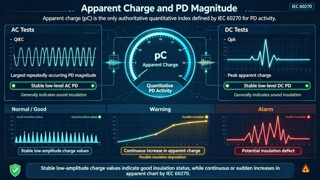
Apparent charge (pC) is the only authoritative quantitative index defined by IEC 60270 for PD activity. The standard distinguishes two core indicators: QIEC (largest repeatedly occurring PD magnitude for AC tests) and Qpk (peak apparent charge for DC tests). Stable low-amplitude charge values indicate good insulation status, while continuous or sudden increases in apparent charge suggest potential insulation defects.
PD Patterns and Phase-Resolved Information
PRPD phase patterns specified in Annex E help verify PD signal validity. Valid transformer PD signals have fixed phase distribution characteristics, while random interference pulses show disordered phase distribution. Pattern analysis eliminates misjudgment of interference and improves result accuracy.
IEC 60270 Transformer PD Testing: Common Compliance Problems
Uncalibrated or Incorrectly Calibrated Measurement System
Most non-compliant test data stems from single-point instrument calibration instead of full-circuit calibration. Cable attenuation and coupling device loss are ignored, leading to inaccurate scale factors and distorted pC readings, failing 2025 edition compliance requirements.
Excessive Background Noise
On-site industrial interference causes high noise floors, making low-amplitude PD signals unrecognizable. Unrecorded noise data leads to unsubstantiated test results, unable to pass third-party audit verification.
Incorrect Test Circuit Configuration
Non-standard grounding, unshielded cables, or mismatched impedance cause signal resonance and pulse distortion, violating IEC 60270 test circuit specifications and reducing measurement repeatability.
Inconsistent Measurement Conditions
Changes in test voltage duration, ambient temperature and humidity, and circuit layout during repeated tests lead to inconsistent data, losing cross-test comparison value.
Treating Any Detected Pulse as Partial Discharge
A key compliance misunderstanding: pulse detection does not equal valid PD measurement. Only repetitive, phase-regular pulses above the noise floor after system calibration are compliant IEC 60270 PD data.
IEC 60270 Compliance Checklist for Transformer PD Monitoring
This full-process checklist covers all IEC 60270 requirements for on-site testing, enabling one-click compliance verification:
| Checkpoint | Verification Standard |
|---|---|
| 1. Applicable standard edition confirmed | Latest IEC 60270:2025 adopted, old 2000 edition invalid |
| 2. Transformer test configuration documented | Wiring, environment, and equipment status fully recorded |
| 3. Standard test circuit configured | Compliant with 2025 edition circuit architecture |
| 4. Qualified PD measuring system selected | Supports charge-based measurement and digital processing |
| 5. Measurement frequency verified | Bandwidth matches test scenario and noise conditions |
| 6. Background noise checked and recorded | Stable noise floor confirmed before formal testing |
| 7. Full system calibration completed | Annex A compliant calibration with valid records |
| 8. Test voltage accurately controlled | Voltage parameters meet standard and project requirements |
| 9. PD data fully measured and recorded | Apparent charge, phase, and activity data complete |
| 10. Measurement conditions archived | All test parameters traceable and repeatable |
| 11. Results evaluated compliantly | Judgment based on standard measurement framework |
| 12. Standard test report completed | Meets audit and project delivery requirements |
IEC 60270 vs. Transformer-Specific PD Testing Standards
IEC 60270 provides the universal foundational framework for global charge-based PD measurement, unifying test circuits, calibration methods, data definitions, and operation procedures. Transformer-specific industry standards and project specifications will formulate targeted test conditions, duration requirements, and acceptance limit criteria based on IEC 60270 baseline rules. As specified in the official standard text, IEC 60270 provisions can be used to compile PD measurement specifications for all power equipment including transformers.
IEC 60270 Transformer PD Measurement: Frequently Asked Questions
What is IEC 60270 used for in transformer PD measurement?
IEC 60270 is the global unified standard for charge-based transformer PD testing, standardizing full-process specifications for circuit construction, system calibration, noise control, testing operations, and data recording to ensure test consistency across different teams and regions.
Does IEC 60270 define a specific transformer PD acceptance limit?
No. IEC 60270:2025 is a measurement standard rather than an acceptance standard. It only defines standardized measurement methods and data indicators, without specifying universal pass/fail pC limits. Acceptance thresholds are determined by transformer-specific standards, project contracts, and utility asset management specifications.
What is IEC 60270 apparent charge?
Apparent charge is the core quantitative PD index defined by the standard, referring to the equivalent charge injected at the transformer terminal that produces the same instrument reading as actual PD pulses. Measured in pC, it is the only valid index for standardized PD result comparison.
Why is calibration required for IEC 60270 PD measurement?
On-site circuit differences cause signal attenuation deviations. Full-circuit calibration corrects system scale factors, eliminates systematic errors, and ensures apparent charge readings are true, repeatable, and compliant with IEC 60270:2025 normative requirements.
What is an IEC 60270 test circuit?
A standardized end-to-end PD signal acquisition circuit composed of HV source, test transformer, coupling device, measuring impedance, and PD instrument. It ensures complete and undistorted collection of PD pulses, complying with 2025 edition circuit configuration and performance check rules.
Can online transformer PD monitoring use IEC 60270?
IEC 60270:2025 mainly applies to laboratory and on-site offline charge-based PD testing. Online continuous monitoring and high-frequency non-electrical detection methods involve other supplementary specifications and technical documents, not fully covered by this standard.
Key Takeaways for IEC 60270-Compliant Transformer PD Measurement
Compliant IEC 60270 for transformer PD monitoring relies on standardized full-process control rather than single equipment compliance. Core key takeaways are summarized as follows:
- Adopt the latest IEC 60270:2025 edition and abandon outdated 2000 edition rules to ensure test validity
- Build test circuits strictly per standard specifications to guarantee signal fidelity and stability
- Select analog/digital dual-mode compatible PD measuring systems matching test scenarios
- Control and record background noise comprehensively to avoid false PD judgment
- Complete full-circuit calibration per updated Annex A requirements to ensure data accuracy
- Implement standardized test procedures to unify operation logic and test conditions
- Archive all test parameters and calibration data to support result traceability and audit
For projects requiring professional transformer PD monitoring and testing services, the measurement system and workflow must be strictly matched with IEC 60270:2025 specifications to deliver repeatable, comparable, and audit-ready test results.
Reference & Technical Sources
- IEC 60270:2025, High-voltage test techniques – Charge-based measurement of partial discharges, 4th Edition, June 2025 (Replaces IEC 60270:2000 + AMD1:2015)
- EN IEC 60270:2025, European Adoption of IEC 60270:2025, July 2025
- IEC TS 62478, High-frequency partial discharge measurement supplementary specification
- IEC 60060-2:2025, High-voltage test techniques – Measuring systems