

A ground fault locator is an instrument that finds the distance along a buried or overhead cable where a conductor has failed to insulation and is leaking current to earth. It is the device that turns an outage into a repairable event: without it, a crew can dig blindly along a route and miss the fault by metres, or damage healthy cable while chasing a false reading. The instrument works by injecting a pulse or a signal into the cable and reading the reflection or the field it produces at the fault, then converting the measurement into a distance.
Author: Zhang Wei, Senior Power Test Engineer, Baoding Houfeng Trading Co., Ltd. — 12 years in cable diagnostics and high-voltage test equipment LinkedIn
Reviewed by: Li Ming, PE — verified against IEEE 1234-2019, IEEE C37.114-2014 and IEEE 81-2012
Last updated: 2026-10-27
What is ground fault locator
A ground fault locator is an instrument that finds the distance along a buried or overhead cable where a conductor has failed to insulation and is leaking current to earth. It is the device that turns an outage into a repairable event: without it, a crew can dig blindly along a route and miss the fault by metres, or damage healthy cable while chasing a false reading. The instrument works by injecting a pulse or a signal into the cable and reading the reflection or the field it produces at the fault, then converting the measurement into a distance.
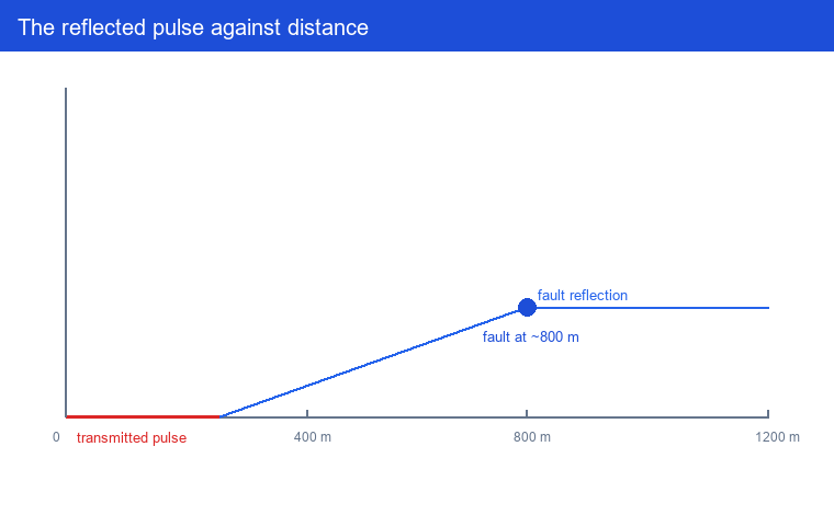
There are three measurement families, and each suits a different fault type. A time domain reflectometer (TDR) sends a low-voltage pulse and reads the reflection; it is fast, safe and best for open circuits, short circuits and low-resistance faults. A thumper, also called a surge generator or capacitor discharge unit, applies a high-voltage pulse that forces the fault to flash over, converting a high-resistance leak into a low-resistance short for one instant so the TDR can measure it. A receiver then picks up the electromagnetic or acoustic signal radiated at the flashover to pinpoint the exact surface position. Understanding which family the duty needs is the first selection decision.
Fault types and how each is located
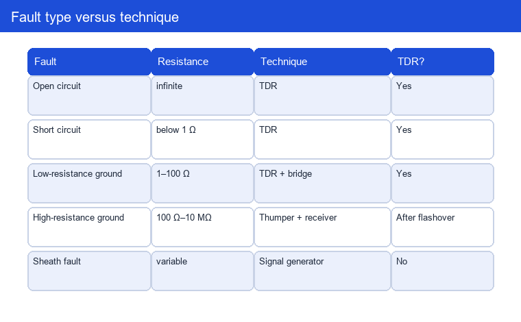
The fault type decides the technique, not the reverse. The four most common conditions on distribution cable are open circuit, short circuit, low-resistance ground fault and high-resistance ground fault. An open circuit or a dead short produces a strong, clean TDR reflection and needs no further conditioning. A low-resistance fault, typically below a few ohms, still reflects but with a smaller and less distinct echo, so the crew may combine TDR with a bridge or a Murray loop to tighten the estimate. A high-resistance fault, often hundreds of ohms to tens of kilohms, reflects so little that the TDR reads only noise; this is where the thumper earns its place.
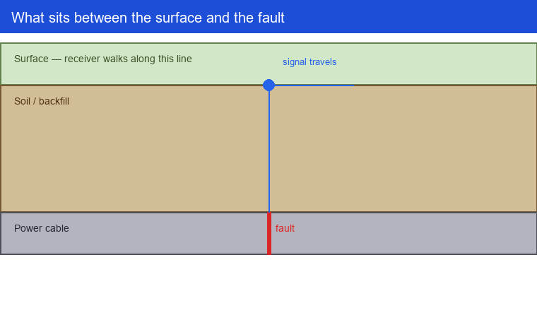
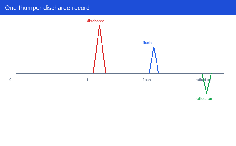
A thumper fault locator combines the surge generator and the receiver in one box. The surge unit charges a capacitor bank to a high voltage and discharges it through the cable at a set repetition rate; the discharge current forces the fault to flash, and the resulting voltage drop makes the fault look like a short for the few milliseconds the TDR measures. The receiver then listens for the electromagnetic pulse or the acoustic shock at the surface and triangulates the position. For underground cable the electromagnetic method is preferred because the signal is cleaner than the sound; the acoustic method is useful when the cable is in a noisy industrial plant.
Key specifications to compare
The specifications separate a general-purpose instrument from one that will actually finish the job. The first is fault resistance range, the maximum resistance the instrument can force to flash; a value of 10 MΩ or more covers the worst high-resistance faults seen in service, while a budget unit may stop at 1 MΩ. The second is TDR resolution, the shortest pulse width and therefore the smallest gap between two reflections the instrument can resolve; a 5 ns pulse resolves roughly one metre of cable, which is what distinguishes a joint from a fault. The third is output voltage and energy, because the flashover depends on the capacitor bank being able to deliver enough current at the right voltage; a 5 kV, 100 mJ unit handles most distribution faults, while transmission-class work needs 15 kV or more.
The fourth is cable length and voltage rating, the maximum distance and the maximum cable voltage the instrument is rated to test safely; exceeding the rating risks damaging healthy cable or endangering the operator. The fifth is mapping and path tracing, the ability to display the cable route and the fault position on a screen rather than as a number; this cuts excavation time sharply. The sixth is portability and power, whether the unit runs on battery for a full shift in the field. When comparing two units, weight these six in the order the duty demands, and read the guaranteed specifications, not the typical ones.
| Fault type | Resistance | Best technique | TDR needed | Typical distance |
|---|---|---|---|---|
| Open circuit | infinite | TDR | Yes | whole length |
| Short circuit | below 1 Ω | TDR | Yes | whole length |
| Low-resistance ground | 1–100 Ω | TDR + bridge | Yes | whole length |
| High-resistance ground | 100 Ω–10 MΩ | Thumper + receiver | After flashover | up to 30 km |
| Sheath fault | variable | Signal generator + receiver | No | up to 15 km |
| Partial discharge | above 10 MΩ | VLF + PD detector | No | not for distance |
Standards and test setup
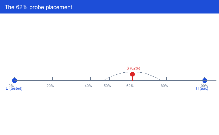
The work rests on three documents. IEEE 1234-2019 is the guide for fault-locating techniques on shielded power cable systems; it describes the TDR, the surge, the bridge and the receiver methods, the conditions under which each applies, and the limitations of each measurement. IEEE C37.114-2014 is the guide for determining fault location on AC transmission and distribution lines; it covers impedance-based and traveling-wave methods, the effect of fault resistance, and the application considerations for underground cable, series-compensated line and parallel line. IEEE 81-2012 is the guide for measuring earth resistivity, ground impedance and earth surface potentials; it defines the fall-of-potential method, the 62% (IEEE 81-2012) rule for probe placement, and the safety conditions for ground testing.
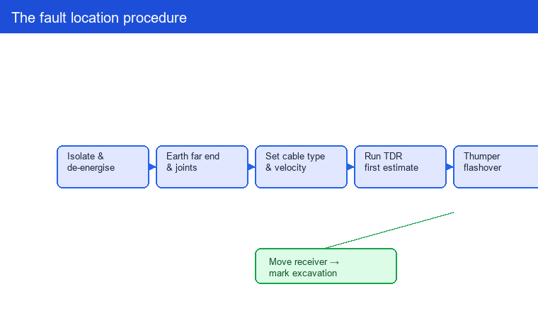
The test setup follows a fixed sequence. First, isolate and de-energise the cable and confirm the fault is isolated from all sources, because a thumper applies a high voltage and a fault under live condition is a hazard. Second, de-energise and earth the cable at the far end and at every intermediate joint to remove stored charge and to prevent the pulse from reflecting off the far end. Third, set the cable type and length in the instrument so the propagation velocity is correct; the velocity is a property of the insulation, and a wrong setting moves every distance reading. Fourth, run the TDR to obtain the first estimate, then apply the thumper to convert the fault to a low resistance and re-measure. Fifth, move the receiver along the route to find the strongest signal at the surface and mark the position for excavation.
The setup is not complete without cable identification. On a route with several parallel cables, applying the signal to the wrong one produces a reading for the wrong cable. A cable identifier or a path tracer should confirm the cable before the thumper is connected. Skipping this step is the single most common cause of a wrong location and a wasted excavation.
Boundary and limitations
First, the device gives a distance, not a repair. It narrows the fault to a metre-scale interval along the route; it does not tell you the exact depth, the cable size, or whether the fault is a single point or a section of degraded insulation. Excavation, test and repair are separate tasks with separate equipment.
Second, the accuracy of a TDR reading depends on the propagation velocity being set to match the cable insulation. The velocity is a measured property of the cable and is only exact when the operator enters the correct value; a wrong entry shifts every reading by a fixed percentage. A velocity error of 5% moves a 10 km reading by 500 m (IEEE 1234-2019). Where the cable type is unknown, a velocity test on a known length should be run first.
Third, the flashover is not guaranteed. A fault resistance above the instrument’s maximum output, a fault in a section of cable that cannot hold the applied voltage, or a cable with a cooling system that removes the heat before the discharge can all prevent the fault from flashing. In these cases the TDR will still give a rough distance, but the receiver will not find a surface position, and the crew must accept the coarser estimate or change technique. The technique is bounded by the cable and the fault, not by the instrument.
Key takeaways
- The instrument turns an outage into a repairable event by converting a reflection or a field into a distance.
- The fault resistance decides the technique: TDR for open and short circuit, thumper for high resistance, receiver for pinpointing.
- Compare the fault resistance range, TDR resolution, output voltage and energy, cable length and voltage rating, mapping, and portability.
- Follow IEEE 1234-2019 for cable technique, IEEE C37.114-2014 for line technique, and IEEE 81-2012 for ground testing.
- Set the propagation velocity correctly, isolate and earth the cable, and confirm the cable identity before thumping.
Frequently asked questions
What is the difference between a thumper and a TDR in the locator?
A TDR injects a low-voltage pulse and reads the reflection; it is fast and safe and works best for open circuit, short circuit and low-resistance faults. A thumper applies a high-voltage pulse that forces a high-resistance fault to flash over, converting it to a short for the instant the TDR measures. The two work together: the TDR gives the distance, the thumper makes a high-resistance fault visible to the TDR.
How far can the instrument measure?
The distance depends on the cable length, the pulse energy and the propagation velocity setting. A typical distribution-class instrument measures up to 15 km on a single pulse, and transmission-class units reach 30 km or more. The receiver that pinpoints the surface position has a shorter range, usually a few tens of metres around the fault, because the electromagnetic and acoustic signals attenuate with distance.
What is the 62% rule in ground testing?
The 62% rule, defined in IEEE 81-2012, places the potential probe at 62% (IEEE 81-2012) of the distance between the tested ground and the auxiliary current probe so that the measured voltage equals the ground potential rise of the tested ground without the influence of the auxiliary probe. It assumes uniform soil and hemispherical electrodes; where those conditions are not met, the fall-of-potential curve should be swept instead.
Can the device find a fault on a live cable?
No. The cable must be isolated, de-energised and earthed before a thumper is connected, because the instrument applies a high voltage. Some path tracers and identifiers can trace a live cable, but the fault-locating pulse and the thumper require the cable to be dead and earthed. Safety comes before measurement, and IEEE 1234-2019 is explicit on this point.
How does the locator differ from a cable identifier?
A cable identifier confirms which of several parallel cables is the one under test by applying a signal and reading it at the far end; it solves the “which cable” problem. A ground fault locator solves the “where on the cable” problem by measuring the reflection or the field at the fault. The two are used in sequence: identify the cable, then locate the fault, then confirm the position before excavation.
What is a line fault locator used for?
A line fault locator is the overhead counterpart of the cable thumper. It applies a pulse to an overhead distribution or transmission line and reads the reflection or the traveling wave to find the fault distance along the span. The same impedance and traveling-wave methods described in IEEE C37.114-2014 apply to both overhead and underground, but the line fault locator is built for the longer distances and the exposed conductor of the overhead route, where the cable thumper is not practical.
Conclusion
A ground fault locator is the instrument that ends an outage search. It reads the fault type, applies the right technique, and returns a distance that a crew can act on. The selection decision is the fault resistance the cable actually presents, the resolution the operator needs, and the voltage the cable requires; the specification list is the guide, not the price. The standard reference is IEEE 1234-2019 for cable technique, IEEE C37.114-2014 for line technique, and IEEE 81-2012 for ground testing. Set the propagation velocity correctly, confirm the cable identity before thumping, and the location will hold up when the excavation begins.
Explore related cable test equipment
The full cable tester range covers every step from identification to pinpointing. Four instruments are worth comparing for a ground fault location campaign:
- HF-CH-224 Mining Cable Marking Machine — marks the identified cable so the route is never lost between the locator and the excavation crew.
- HF-CH-223 Smart Utility Locator — traces the buried cable path and depth before the fault pulse is applied.
- Cable Fault Pinpointer — the receiver that finds the exact surface position after the thumper flashover.
- Surge Generator for Cable Fault Location — the thumber that forces a high-resistance fault to flash over.
Contact our engineering team for a fault location campaign plan tailored to your cable route, or request a datasheet for the units above.