Leave your message

-
Leon Zhang sales consultant
-
Phone/WhatsApp/Wechat: +86 13655813266

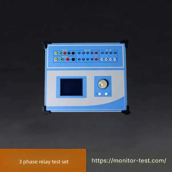
HF-RT-202 3 Phase Relay Test set
This 3 Phase Relay Test Set performs full-range Protective Relay Testing. It outputs three independent voltage and current sources to simulate various grid faults, calibrating substation protection relays strictly compliant with IEC and ANSI international power industry specifications.
Send your requirements, we will quote for you within 12 hours
- It fulfills all on-site testing requirements, equipped with standard 4-phase voltage and 3-phase current outputs. It can test traditional relays, protection devices as well as modern microprocessor-based protection equipment, enabling simpler and more comprehensive tests especially for transformer differential protection and automatic bus transfer devices.
- All technical parameters fully comply with DL/T624-1997 Technical Conditions for Microcomputer-Based Relay Protection Test Devices issued by the Ministry of Electric Power.
- Adopting the classic Windows XP operating system, it features a user-friendly human-machine interface for easy and efficient operation. Equipped with a high-performance embedded industrial controller and a 10.4-inch 800×600 LED true-color display screen, it displays abundant intuitive information including real-time operating status and various help prompts.
Technical Specifications
AC Current Source (3×30A)
| Item | Parameters |
|---|---|
| Single-phase current output (RMS) | 0~30A per phase, accuracy: 0.2% ±5mA |
| 3-phase parallel output (RMS) | 0~90A, three phases output in parallel with identical phase |
| Long-term permissible continuous working current per phase (RMS) | 10A |
| Maximum output power per phase | 300VA |
| Max total output power for three parallel currents | 800VA |
| Max allowable working duration for combined 3-phase parallel current | 10s |
| Frequency range | 0~1000Hz, accuracy: 0.01Hz |
| Harmonic orders | 2~20 orders |
| Phase angle | 0~360°, accuracy: 0.1° |
DC Current Source
| Item | Parameters |
|---|---|
| DC current output | 0~±10A per phase, accuracy: 0.2% ±5mA |
AC Voltage Source
| Item | Parameters |
|---|---|
| Single-phase voltage output (RMS) | 0~125V per phase, accuracy: 0.2% ±5mV |
| Line voltage output (RMS) | 0~250V |
| Output power (Phase voltage / Line voltage) | 75VA / 100VA |
| Frequency range | 0~1000Hz, accuracy: 0.001Hz |
| Harmonic orders | 2~20 orders |
| Phase angle | 0~360°, accuracy: 0.1° |
DC Voltage Source
| Item | Parameters |
|---|---|
| Peak value of single-phase voltage output | 0~±150V, accuracy: 0.2% ±5mV |
| Peak value of line voltage output | 0~±300V |
| Output power (Phase voltage / Line voltage) | 90VA / 180VA |
Switch Quantity Terminals
| Item | Parameters |
|---|---|
| Digital input terminals | 8 pairs |
| Idle contact | 1~20mA, built-in 24V power supply inside the device |
| Potential reversal | Passive contact: low-resistance short-circuit signal Active contact: 0~250V DC |
| Digital output terminals | 4 pairs, vacant contacts; Breaking capacity: 110V/2A, 220V/1A |
Other Parameters
| Item | Parameters |
|---|---|
| Time range | 1ms~9999s, measurement accuracy: 1ms |
| Dimension & Weight (Portable model) | Overall size: 338 × 168 × 305 mm, approx. 12 kg |
| Power Supply | AC 220V ±10%, 50Hz, 10A |
Continuous Working Time of AC Current
| Operating Current | Allowable Working Duration |
|---|---|
| Operating current ≤ 10A | More than 60 minutes |
| 10A < Operating current ≤ 20A | More than 70 seconds |
| 20A < Operating current ≤ 30A | More than 15 seconds |
| Operating current = 30A | More than 5 seconds |
Operation Procedure for 3 Phase Relay Test Set
Step 1: Pre-Operation Preparation
- Inspect the tester, test leads, power cord and all accessories for intactness before use.
- Place the unit on a flat, stable platform; connect the AC220V power supply firmly.
- Confirm the tested relay/protection device is fully powered off and grounded safely to avoid electric hazards.
Step 2: Wiring Connection
- Connect 3-phase current output terminals and 4-phase voltage output terminals of the tester to the corresponding secondary terminals of the protective relay via insulated test wires.
- Link switch quantity input/output cables between the tester and relay trip/auxiliary contact ports.
- Plug the USB communication cable if you need to control the tester via an external laptop.
Step 3: Boot Up & Software Initialization
- Turn on the power switch to start the device; the built-in Windows XP system loads automatically.
- Launch the dedicated relay test software on the touch screen. Complete system self-check and automatic precision calibration.
- Select corresponding test items: overcurrent protection, transformer differential protection, auto-switch device test etc. according to on-site testing requirements.
Step 4: Parameter Setting & Fault Simulation
- Set output current, voltage, frequency, phase angle, harmonic parameters and action threshold values on the software interface.
- Configure fault types: short circuit, earth fault, voltage loss, abnormal frequency and other grid fault conditions.
- Adjust test duration and recording modes as needed.
Step 5: Start Testing & Record Data
- Preview the output waveform to verify all settings are correct, then run the test program formally.
- Observe relay tripping action, record operating time, action value and other key test data synchronously.
- Repeat tests multiple times to check protection action consistency and accuracy.
Step 6: Save Test Results
- After testing finishes, store test reports, waveform curves and parameter records in the system.
- Export data to USB flash drive for filing, printing or further analysis.
Step 7: Shutdown & Post-Use Arrangement
- Reset all output values to zero, close the test software properly.
- Shut down the operating system normally, then cut off the main power supply.
- Disconnect all test wires one by one, tidy up cables, pack all accessories into the shipping case.
FAQ for 3 Phase Relay Test Set
Q1: What is this 3 Phase Relay Test Set used for?
A1: It is professional equipment for Protective Relay Testing. Equipped with 3-channel current & 4-channel voltage outputs, it simulates power grid faults to calibrate conventional relays, microcomputer protection devices, transformer differential protection and automatic bus transfer devices for power substations.
Q2: Which technical standards does this tester comply with?
A2: Its all technical indicators fully meet DL/T624-1997 standard issued by China Ministry of Electric Power, and it is also applicable to global IEC & ANSI power industry testing specifications.
Q3: What is the maximum single-phase output current? Can three phases be connected in parallel?
A3: Single-phase AC current output: 0~30A. Three phases can be paralleled to achieve a total maximum output current of 90A for high-current testing demands.
Q4: How long can the large current output work continuously?
A4: Working time varies by current: ≤10A: over 60 mins; 10~20A: over 70s; 20~30A: over 15s; Rated 30A: over 5s, to protect the internal power amplifier module.
Q5: Does it support harmonic generation and phase adjustment?
A5: Yes. It supports 2~20 orders of harmonics, phase angle adjustable 0~360° (accuracy 0.1°), frequency range 0~1000Hz for flexible fault simulation.
Q6: What operating system does the tester adopt? Can I operate it via laptop?
A6: It runs built-in Windows XP system with 10.4-inch LED true color screen. You can connect an external laptop via USB cable; both sides share the same control software.
Q7: Does manual calibration need to be done regularly to keep testing accuracy?
A7: No need for frequent manual adjustment. The device supports automatic software calibration to maintain long-term testing precision steadily.
Q8: What interfaces are available for communication connection?
A8: Standard USB interface is equipped, plug-and-play, no extra adapters required for PC connection and data transmission.
Q9: Can it test transformer differential protection and automatic bus transfer devices?
A9: Definitely. The 3-phase current + 4-phase voltage layout is specially optimized for these two types of protection tests, with simpler operation and more reliable test results.
Q10: Does the device have switching value input and output ports?
A10: It has 8 pairs of digital input terminals and 4 pairs of digital output terminals, which can perfectly collect relay trip signals and output control signals during testing.
Reviews
There are no reviews yet.