

Introduction
Transformer partial discharge detection is based on the physical signals generated by PD activity in transformer insulation systems. When partial discharge occurs, it can produce different types of signals that can be detected from outside the transformer.
These signals mainly include electromagnetic emissions, high-frequency current pulses and acoustic signals. Each signal type reflects a different aspect of PD activity and propagates in a different way.
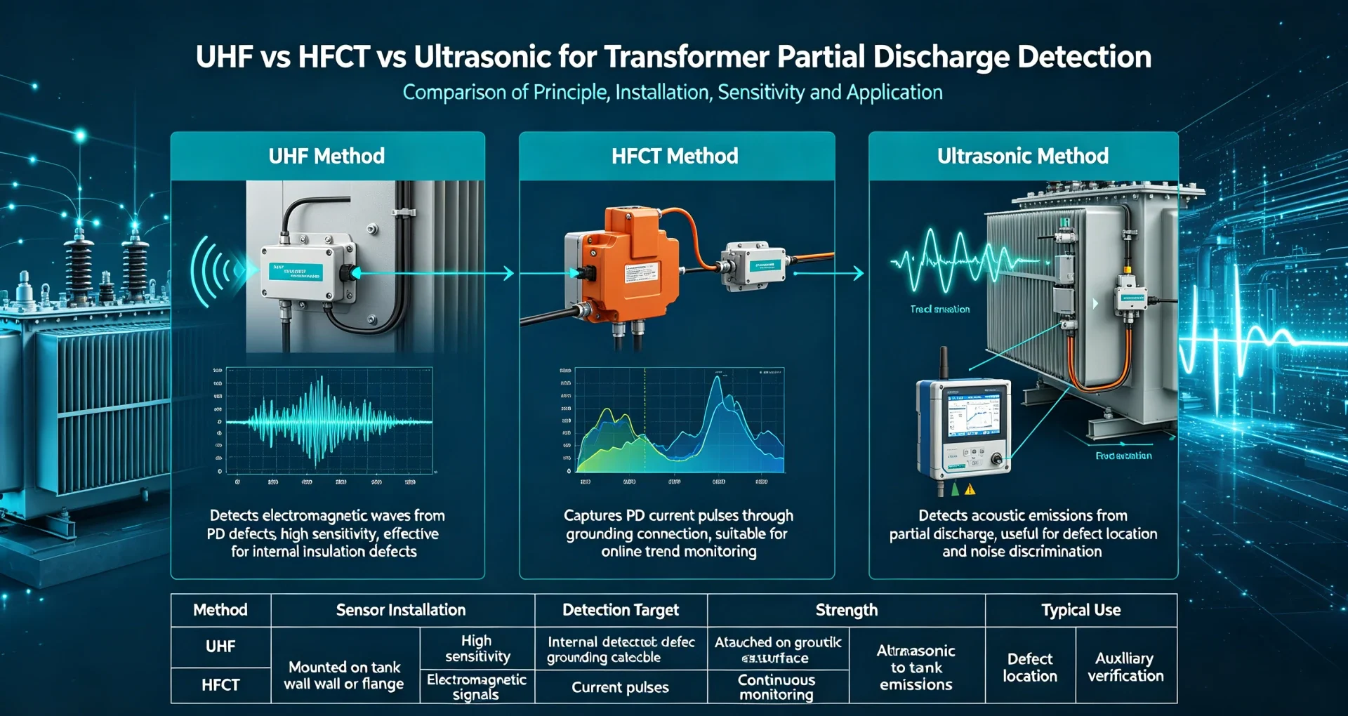
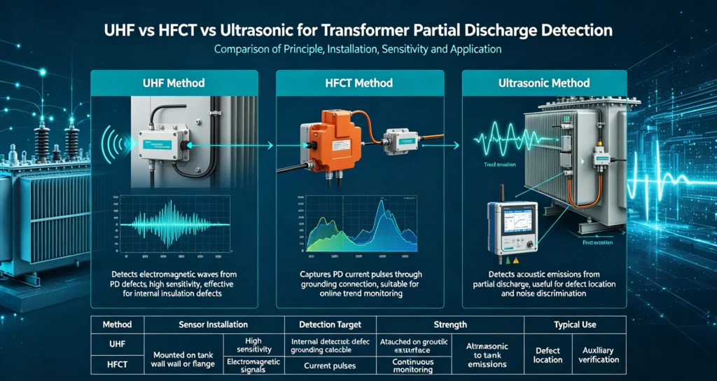
Based on these signal types, three main transformer partial discharge detection technologies are commonly used: UHF, HFCT and ultrasonic detection. Each method detects a different physical signal and has different installation requirements, interference characteristics and localization capabilities.
This guide explains how each transformer partial discharge detection method works and compares their practical applications.
How Does Partial Discharge Produce Detectable Signals?
The complete PD generation and detection chain follows a fixed logic: inherent insulation defects (bubbles, cracks, impurities) → localized electric field concentration → intermittent partial discharge → multi-physical signal radiation → sensor acquisition and signal analysis → insulation
PD activities inside transformers generate three independent types of measurable signals, corresponding to the three mainstream detection technologies:
- Electromagnetic signals: High-frequency electromagnetic waves radiated outward during discharge, captured by UHF sensors
- High-frequency current pulses: Transient current generated by discharge, transmitted along transformer grounding loops, captured by HFCT sensors
- Acoustic/ultrasonic signals: Mechanical vibration waves generated by discharge impact on oil and tank structures, captured by ultrasonic acoustic sensors
The fundamental difference between the three detection methods lies in the different physical signals they collect, which directly determines their performance differences in field transformer PD monitoring.
UHF Partial Discharge Detection for Transformers
UHF (Ultra-High Frequency) partial discharge detection is a mainstream high-precision online monitoring technology, widely used in online transformer PD detection for high-voltage core substation transformers. It complies with IEC 62478 standard specifications for high-frequency electromagnetic PD measurement.
How UHF PD Detection Works
Internal transformer PD produces ultra-high-frequency electromagnetic signals (300 MHz – 3 GHz). These signals penetrate the transformer oil and tank gaps and are captured by dedicated UHF sensors installed at transformer flange ports, valve openings, or reserved sensor interfaces. The system filters low-frequency environmental interference through professional signal processing, extracts valid PD pulse waveforms, and realizes PD pattern identification, defect judgment, and multi-point localization.
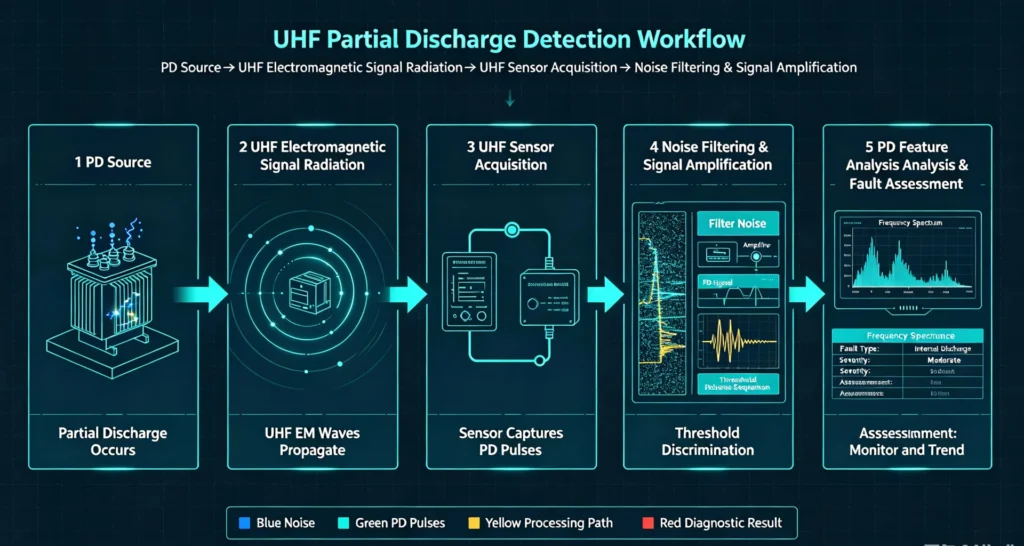
Working flow: PD Source → UHF Electromagnetic Signal Radiation → UHF Sensor Acquisition → Noise Filtering & Signal Amplification → PD Feature Analysis & Fault Assessment
Advantages of UHF Transformer PD Detection
- Excellent anti-interference performance: Most on-site low-frequency interference (power line carrier, mobile communication, corona noise) is concentrated below 300 MHz, causing minimal impact on UHF band signals, ensuring stable detection in complex substation electromagnetic environments
- Adaptable to long-term online monitoring: Supports 24/7 uninterrupted transformer partial discharge monitoring, capable of tracking insulation aging trends
- Accurate PD pattern analysis: Rich high-frequency signal features support classification of discharge types (air gap discharge, creepage discharge, metal particle discharge)
- Reliable multi-sensor localization: Multiple UHF sensors arranged in groups can calculate PD source position via signal time difference analysis, providing accurate fault location data
Limitations of UHF Detection
- Detection depends on transformer structure: Fully sealed transformers without reserved sensor ports increase installation difficulty
- High-frequency signal attenuation exists: Signal loss occurs during penetration of tank walls and insulation structures, affecting detection sensitivity for deep internal defects
- High system complexity: Requires professional debugging and frequency calibration, with higher overall system cost
Applicable Scenarios for UHF Detection
UHF is the preferred solution for high-value core transformer assets that require long-term stable online monitoring: 110kV and above substation main transformers, generator step-up transformers, key industrial power supply transformers, and equipment requiring high-frequency electromagnetic PD signal identification and continuous transformer insulation condition monitoring.
HFCT Partial Discharge Detection for Transformers
HFCT (High-Frequency Current Transformer) detection is a simple, practical electrical PD testing technology, focusing on high-frequency pulse current signals generated by PD. It is the most widely used auxiliary method for on-site transformer PD detection and routine condition screening.
How HFCT Detects Partial Discharge
PD activities inside transformers generate transient high-frequency current pulses (3 MHz – 30 MHz). These pulses flow through the transformer’s grounding conductor and grounding loop. The clamp-on HFCT sensor is directly installed on the grounding cable to inductively capture transient current signals. After amplification, filtering, and waveform analysis, the system judges whether abnormal PD exists.
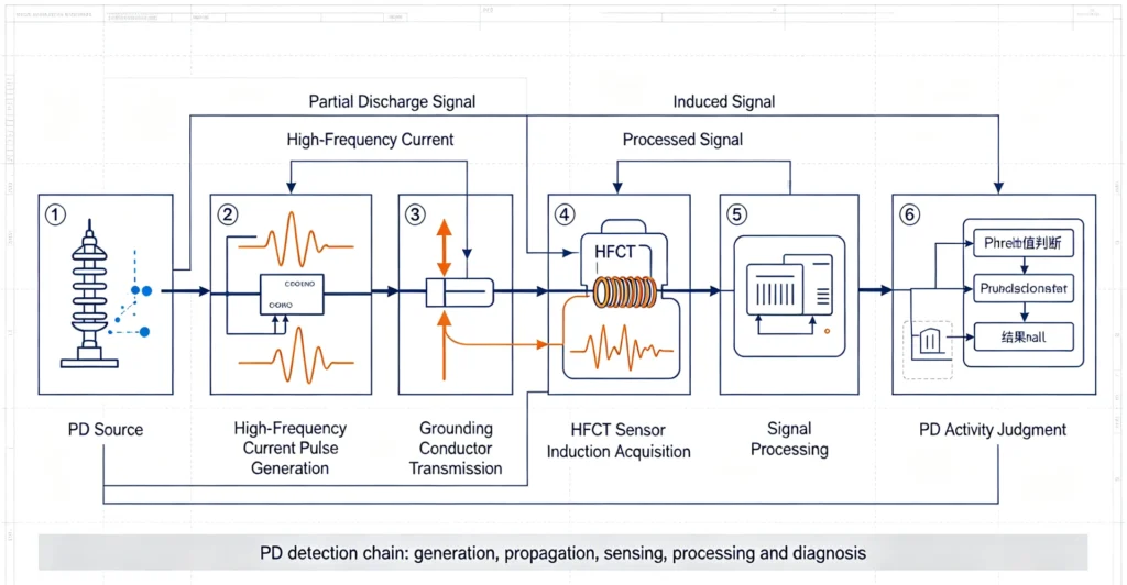
Working flow: PD Source → High-Frequency Current Pulse Generation → Grounding Conductor Transmission → HFCT Sensor Induction Acquisition → Signal Processing → PD Activity Judgment
Advantages of HFCT Detection
- Ultra-low installation difficulty: Clamp-on non-intrusive installation requires no disassembly of transformer body or reserved interfaces, suitable for all in-service transformers
- Stable online monitoring capability: Supports live-line detection and long-term online transformer PD monitoring without affecting transformer normal operation
- Low cost and high practicability: Simple system structure, convenient daily maintenance, very suitable for large-scale routine PD screening of distribution transformers
- Direct electrical signal response: Directly captures PD current pulses, with intuitive signal characteristics and easy threshold judgment
Limitations of HFCT Detection
- Signal quality is restricted by grounding conditions: Irregular grounding loops or multiple equipment shared grounding will cause signal superposition and interference
- Weak anti-low-frequency interference ability: Susceptible to on-site electrical noise and corona discharge interference, requiring professional filtering algorithm optimization
- Poor independent localization ability: Single HFCT sensor can only confirm PD existence, unable to accurately locate defect positions
Applicable Scenarios for HFCT Detection
HFCT is the best choice for in-service transformers with accessible grounding conductors, distribution station batch equipment screening, daily O&M routine PD testing, and projects requiring low-cost, fast online transformer partial discharge testing.
Ultrasonic Partial Discharge Detection for Transformers
Ultrasonic (acoustic emission) detection is a physical diagnosis technology that captures mechanical vibration signals of PD. It is an indispensable supplementary means for transformer PD detection methods, focusing on fault localization and on-site troubleshooting.
How Ultrasonic PD Detection Works
Internal PD will produce tiny impact vibrations, forming ultrasonic acoustic waves (20 kHz – 300 kHz) that propagate along transformer oil, tank walls, and structural parts. Ultrasonic PD sensors are attached to the outer wall of the transformer tank to collect acoustic signals. Through signal filtering and time-domain analysis, the system eliminates mechanical noise interference and realizes PD source identification and spatial localization.
Working flow: PD Source → Acoustic Wave Generation & Propagation → Ultrasonic Sensor Acquisition → Mechanical Noise Filtering → PD Localization & Fault Diagnosis
Advantages of Ultrasonic PD Detection
- Unique PD localization capability: The only independent detection technology that can realize spatial positioning of internal PD defects for on-site troubleshooting
- Complementary to electrical detection: Makes up for the localization defects of UHF and HFCT, realizing dual verification of electrical and acoustic signals
- Simple field diagnosis: Portable and flexible, suitable for live fault investigation and irregular hidden danger inspection
- No electromagnetic interference: Adopts acoustic signal detection, completely free from substation electromagnetic field interference
Limitations of Ultrasonic Detection
- Serious signal attenuation: Acoustic waves decay rapidly during propagation through oil and metal structures, with low sensitivity for deep internal defects
- Susceptible to mechanical noise: On-site fan vibration, equipment operation noise will interfere with valid PD signals
- High installation position dependence: Sensor placement accuracy directly determines detection effect, requiring rich construction experience
Applicable Scenarios for Ultrasonic Detection
Ultrasonic technology is mainly used for PD source accurate localization, post-fault troubleshooting, suspicious defect verification, and auxiliary diagnosis of complex insulation faults. It is often matched with UHF/HFCT electrical detection to form a comprehensive transformer insulation monitoring solution.
UHF vs HFCT vs Ultrasonic: Core Performance Comparison
The following table intuitively summarizes the core differences of the three partial discharge sensor technologies in detection principle, installation, monitoring performance, and engineering applicability, helping engineers quickly complete preliminary selection.
| Comparison Feature | UHF | HFCT | Ultrasonic |
|---|---|---|---|
| Detection Signal | Ultra-high frequency electromagnetic wave (300MHz–3GHz) | High-frequency current pulse (3MHz–30MHz) | Ultrasonic acoustic wave (20kHz–300kHz) |
| Typical Installation | Transformer tank flange, reserved sensor port | Transformer grounding conductor (clamp-on) | Outer surface of transformer tank |
| Online Monitoring Suitability | Excellent (24/7 continuous monitoring) | Excellent (live-line long-term monitoring) | Conditional support (affected by noise) |
| PD Localization Ability | Good (multi-sensor array positioning) | Limited (only judge signal existence) | Excellent (independent spatial localization) |
| Main Interference Source | High-frequency electromagnetic noise, signal attenuation | On-site electrical noise, grounding loop interference | Mechanical vibration, environmental acoustic noise |
| Installation Complexity | Medium–High | Low–Medium | Medium |
| Core Advantage | High anti-interference, stable long-term monitoring, accurate pattern recognition | Easy installation, low cost, suitable for batch screening | Accurate PD localization, pure physical detection without electromagnetic interference |
| Typical Engineering Application | Core transformer online monitoring, high-precision diagnosis | Daily PD screening, in-service transformer condition monitoring | Fault troubleshooting, PD source positioning, auxiliary diagnosis |
Core engineering conclusion: No single transformer partial discharge sensor can cover all working conditions. The three technologies are complementary rather than mutually substitutable.
UHF vs HFCT vs Ultrasonic: Sensitivity Analysis
Most engineers focus on sensor sensitivity when selecting transformer PD detection methods. However, it is impossible to simply rank UHF, HFCT, and ultrasonic sensors by absolute sensitivity, which is the key to professional and reliable detection scheme design.
Key Factors Determining PD Detection Sensitivity
The actual detection sensitivity of field partial discharge detection for transformers is not determined by sensor parameters alone, but affected by multiple variables:
- Sensor inherent precision and signal acquisition bandwidth
- Signal attenuation degree caused by transformer structure and insulation medium
- Sensor installation position and distance from PD source
- On-site background noise level (electromagnetic, mechanical, acoustic)
- System signal filtering and algorithm processing capability
Why Absolute Sensitivity Ranking Is Unfeasible
UHF, HFCT, and ultrasonic sensors detect completely different physical signals, so their sensitivity evaluation dimensions are inconsistent. HFCT is more sensitive to low-frequency pulse current generated by corona discharge, while UHF is almost immune to such interference and more sensitive to high-frequency electromagnetic signals of internal insulation defects. Ultrasonic sensors only respond to acoustic vibration signals and cannot capture pure electrical PD characteristics.
Blindly pursuing “highest sensitivity” will lead to false alarms or missed detection. Reasonable technology matching based on actual working conditions is the core of high-quality transformer partial discharge detection.
Which Transformer PD Detection Method Is Suitable for Different Applications?
Online partial discharge detection requires long-term stability, low false alarm rate, and no impact on transformer operation. The optimal sensor selection for online monitoring is scenario-based:
Choose UHF for Online Monitoring If:
- Monitoring high-voltage core substation transformers with high asset value
- Requiring high anti-interference performance for complex electromagnetic environments
- Needing long-term continuous trend monitoring and PD pattern analysis
- Requiring multi-point sensor array for PD source localization
Choose HFCT for Online Monitoring If:
- Retrofitting online monitoring for existing in-service transformers
- Grounding conductors are accessible with simple installation conditions
- Prioritizing low cost and convenient construction for batch equipment screening
- Carrying out daily routine transformer PD monitoring and state evaluation
Choose Ultrasonic for Online Auxiliary Monitoring If:
- Needing to verify suspicious PD signals detected by electrical sensors
- Requiring real-time positioning of abnormal discharge sources during online operation
- Supplementary diagnosis for equipment with ambiguous electrical detection results
Can UHF, HFCT and Ultrasonic Sensors Be Used Together?
Multi-technology combined detection is the optimal solution for high-precision transformer partial discharge detection and is widely recognized in industrial and power engineering. Since the three sensors capture independent physical signals, combined application can effectively make up for the shortcomings of single technology and improve diagnosis accuracy.
Complementary Mechanism of Electrical + Acoustic Detection
UHF and HFCT undertake mainstream online PD signal detection and trend monitoring tasks, quickly identifying whether insulation discharge exists and judging discharge severity. Ultrasonic sensors assist in completing spatial localization of PD sources, solving the pain point that electrical detection cannot accurately locate defects.
Advantages of Multi-Sensor Transformer PD Monitoring
- Realize multi-dimensional signal correlation verification, greatly reducing false alarm and missed detection rates
- Complete PD source positioning, discharge type identification, and defect severity assessment in one system
- Support long-term data trend analysis to accurately judge insulation aging degree
- Provide comprehensive data support for transformer maintenance decision-making
Applications of Transformer Partial Discharge Detection
Power Transformer Condition Monitoring
UHF + HFCT combined solution is used for long-term online transformer insulation condition monitoring of 110kV and above power transformers, tracking insulation aging trends in real time.
Substation Transformer Diagnostics
Match UHF high-precision monitoring with ultrasonic localization to realize full-cycle health diagnosis of substation core transformer assets.
Generator Step-Up Transformer Monitoring
Adopt anti-interference UHF detection technology to adapt to complex electromagnetic environments of generator units and ensure stable online transformer PD detection.
Transformer Commissioning & Acceptance
Use HFCT + ultrasonic combined testing to complete PD hidden danger screening for new transformers before grid connection.
Maintenance and Troubleshooting
Ultrasonic positioning assisted by UHF/HFCT signal verification quickly locates fault points and improves maintenance efficiency.
Aging Transformer Insulation Assessment
Multi-sensor joint monitoring accumulates long-term data to accurately evaluate insulation residual life of aging transformers.
How to Select a Transformer Partial Discharge Detection Method
For EPC engineers and project owners, the following standardized selection process can quickly match the most suitable transformer partial discharge detection scheme for project scenarios:
1. Confirm Transformer Type and Voltage Level
High-voltage main transformers prioritize UHF or multi-technology combined solutions; distribution transformers and conventional industrial transformers prefer low-cost HFCT solutions.
2. Clarify Testing Mode: Online or Offline
Long-term real-time monitoring selects UHF/HFCT online systems; regular offline acceptance and troubleshooting selects portable HFCT + ultrasonic combined testing. (Cooperate with our previous article: Online vs Offline Partial Discharge Testing for Transformers)
3. Evaluate On-Site Installation Conditions
Check whether the transformer has reserved sensor ports and whether grounding conductors are accessible. Sealed transformers without ports are not suitable for conventional UHF installation, and HFCT is preferred for priority deployment.
4. Assess On-Site Noise Environment
Substations with strong electromagnetic interference prioritize UHF with high anti-interference performance; sites with serious mechanical vibration reduce single ultrasonic detection dependence.
5. Define Monitoring and Diagnosis Objectives
Daily state screening: HFCT; long-term trend monitoring: UHF; fault positioning and troubleshooting: ultrasonic + electrical detection combination.
6. Match Monitoring System Configuration
Select system channels, sampling frequency, filtering algorithm, remote alarm and data storage functions according to project scale and monitoring precision requirements, ensuring matching with transformer PD sensor performance.
For detailed online/offline testing differences, see our Online vs Offline Partial Discharge Testing for Transformers guide.
Frequently Asked Questions
1. What is transformer partial discharge detection?
Transformer partial discharge detection is the process of identifying PD activity in transformer insulation by detecting the physical signals it generates, such as electromagnetic emissions, high-frequency current pulses and acoustic signals.
2. What are the main transformer partial discharge detection methods?
The three main methods are UHF detection, HFCT detection and ultrasonic (acoustic) detection. Each targets a different physical signal and has different installation and application characteristics.
3. What is the difference between UHF and HFCT for transformer PD detection?
UHF detection captures electromagnetic emissions in the ultra-high-frequency range and is often used for internal PD detection. HFCT detection captures high-frequency current pulses, typically through grounding paths. They detect different signal types and are suited to different installation conditions.
4. Can ultrasonic sensors detect partial discharge in transformers?
Yes. Ultrasonic sensors detect acoustic signals generated by PD activity. They are particularly useful for supporting PD source localization, although their sensitivity can be affected by the transformer structure and background noise.
5. Can UHF, HFCT and ultrasonic sensors be used together?
Yes. The three methods detect different physical signals and can provide complementary information. Using them together can improve detection reliability and support more comprehensive analysis.
6. Which transformer PD detection method is suitable for online monitoring?
This depends on the transformer and application. UHF and HFCT are commonly used for online monitoring where suitable installation conditions exist, while ultrasonic sensors can also support online detection and localization. Method selection should consider transformer construction, installation conditions, noise environment and monitoring objectives.
Conclusion
Transformer partial discharge detection can use different sensing technologies depending on the physical signals available and the engineering objective. UHF detection targets electromagnetic PD signals, HFCT detection targets high-frequency current pulses, and ultrasonic detection targets acoustic signals and supports PD source localization.
No single method is universally suitable for every transformer. Sensor selection should consider transformer construction, installation conditions, noise environment, testing mode and diagnostic objectives.
For applications requiring continuous transformer PD monitoring, see our Transformer PD Monitoring Device.
Technical References & Data Sources
- IEC 60270: High-voltage test techniques – Partial discharge measurements (International Standard)
- IEC 62478: High-voltage equipment – Partial discharge online monitoring specification for power transformers
- IEEE Xplore: Comparative Study of Partial Discharge Localization Based on UHF & HFCT Detection Methods
- Reinhausen: Transformer Online Partial Discharge Monitoring Industry Guideline
- Semantic Scholar: Application Research of Multi-Sensor Fusion in Transformer PD Detection
[…] For a detailed comparison, see: Transformer Partial Discharge Detection: UHF vs HFCT vs Ultrasonic. […]
[…] For more on how these sensors are applied in practice, see Transformer Partial Discharge Detection. […]