

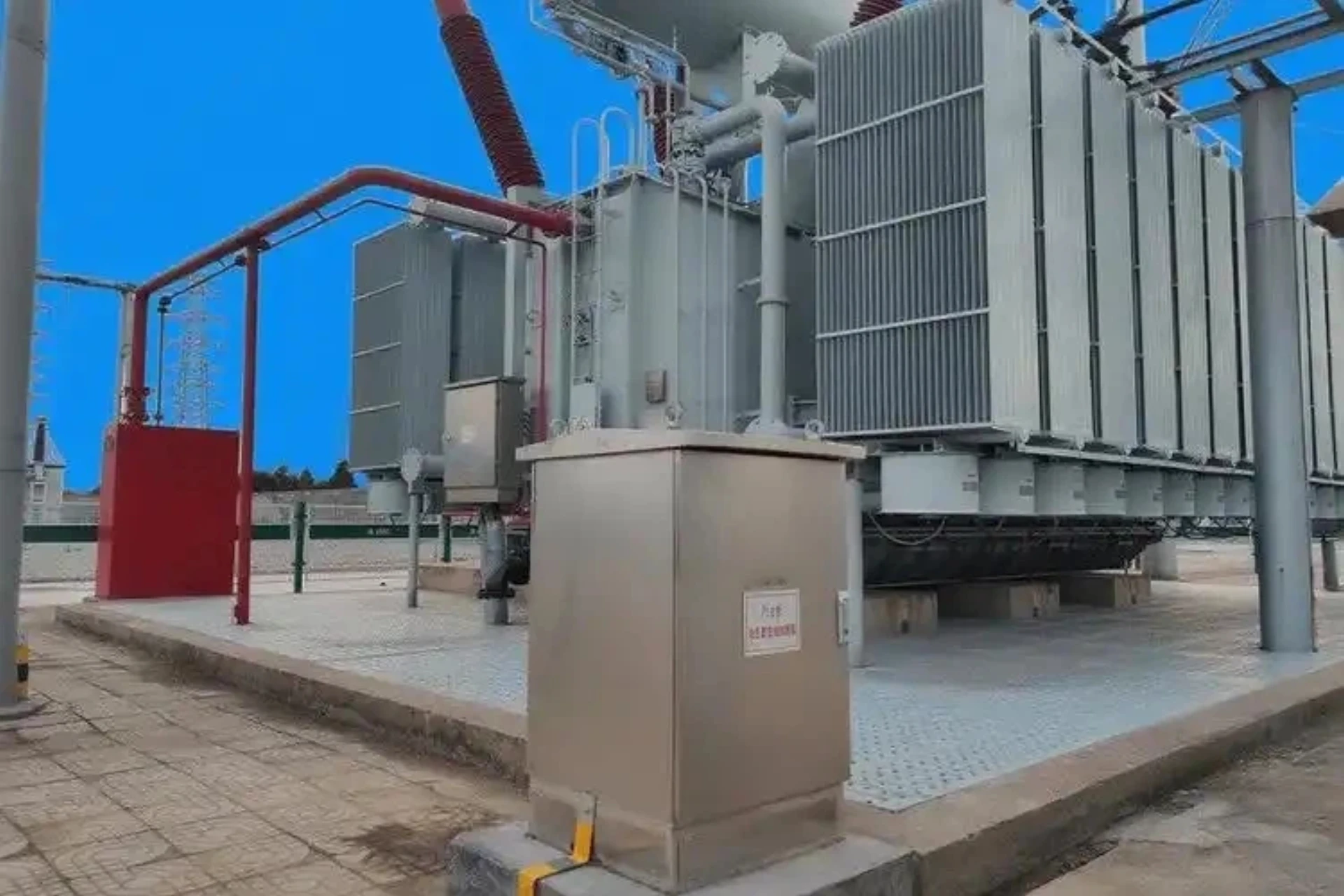
Introduction: How Can Transformer Oil Reveal Internal Faults?
A Transformer DGA Monitoring System is an online condition-monitoring system that continuously measures dissolved gases in transformer oil to detect developing insulation and thermal faults.
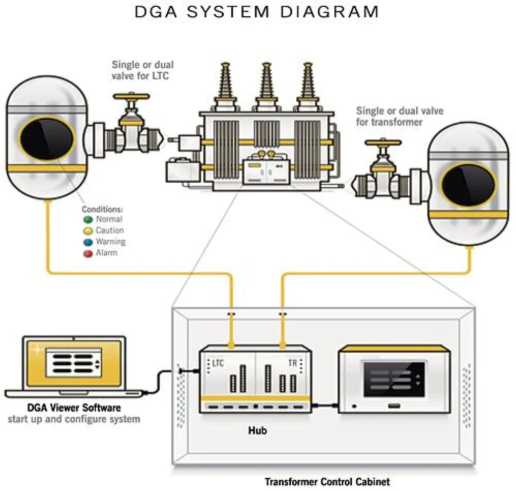
An online DGA monitoring system works by continuously sampling transformer oil, extracting dissolved gases, detecting key gas concentrations, processing the measurement data, and applying diagnostic methods to identify abnormal conditions.
This article elaborates on the full working workflow of a standard dissolved gas analysis system, including oil sampling, gas extraction, precision detection, data diagnosis, alarm output, and remote SCADA interconnection, to help engineering and procurement teams fully understand the operational logic and application value of industrial-grade DGA monitoring equipment.
How Does a Transformer DGA Monitoring System Work?
An online DGA monitoring system continuously samples transformer oil through a closed-loop path, separates dissolved gases via vacuum bubbling, and precisely measures key fault gases — H₂, CH₄, C₂H₆, C₂H₄, C₂H₂, CO, CO₂, O₂, N₂ — plus moisture. Its edge diagnosis engine applies models such as the improved Duval Triangle and Three-Ratio Method to automatically analyze gas concentrations and output fault-type probability evaluations. When thresholds are exceeded, it issues multi-level alarms and transmits data to SCADA, PMS, or centralized platforms via IEC 61850, Modbus, or DNP3. By turning oil sample data into continuous trends and early warnings, online DGA supports actionable maintenance decisions.
| Stage | What Happens |
|---|---|
| Oil Sampling | Transformer oil is continuously or periodically sampled |
| Gas Extraction | Dissolved gases are separated from the oil |
| Gas Detection | Key fault gases are measured |
| Data Processing | Gas concentrations and trends are calculated |
| Fault Diagnosis | Gas patterns are evaluated against diagnostic methods |
| Alarm | Abnormal gas levels or trends trigger alarms |
| SCADA | Monitoring results are transmitted to the control system |
Step 1: Oil Sampling — How the System Obtains Data
In an online DGA monitoring system, a small amount of transformer oil is continuously or periodically routed from the transformer to the monitoring unit through a closed-loop oil path. The sampling point is typically located at the transformer oil sampling port or a dedicated sampling interface, ensuring the oil sample is representative of the actual oil condition inside the transformer. Oil temperature, oil pressure, and oil path sealing must be considered during sampling to avoid measurement inaccuracies caused by temperature fluctuations or pressure abnormalities. The closed-loop circulation design allows the oil sample to return to the transformer after sampling, enabling installation and operation without a power cut while keeping the oil sample continuously updated — providing a stable, representative data source for subsequent gas extraction and detection.
Step 2: Gas Extraction — How Dissolved Gases Are Separated From Transformer Oil
Dissolved gases in transformer oil must first be separated from the oil before entering the detection stage. The system uses an oil-gas separation unit to extract dissolved fault gases from the oil as a gas sample. The separation process typically applies vacuum bubbling principles with self-adaptive degassing volume control, achieving stable degassing in a compact structure while avoiding the clogging and aging issues common to traditional membrane degassing units. The extracted gas sample is then transferred to the detection unit of the dissolved gas analyzer for measurement, completing the conversion from transformer oil to gas sample.
Step 3: Gas Detection — Gas Detection: How Does a Transformer Dissolved Gas Analyzer Measure Fault Gases?
Gas detection is performed by the transformer dissolved gas analyzer, which primarily measures the concentrations of key fault gases including H₂, CH₄, C₂H₆, C₂H₄, C₂H₂, CO, and CO₂. Different gases have typical associations with different types of transformer faults and can serve as diagnostic indications:
| Gas | Typical Fault Association |
|---|---|
| H₂ | Partial discharge / low-energy discharge |
| CH₄ | Low-temperature thermal fault |
| C₂H₆ | Thermal fault |
| C₂H₄ | Higher-temperature thermal fault |
| C₂H₂ | Arcing / high-energy discharge |
| CO | Paper insulation overheating |
| CO₂ | Cellulose insulation aging / degradation |
These associations are typical diagnostic indications, not an absolute one-gas-to-one-fault relationship.
Step 4: Data Processing — How Are DGA Measurements Processed?
The system first obtains individual gas concentrations (ppm) to form independent measurement data. It then performs trend analysis, evaluating gas concentration trends, rate of increase, and abnormal changes, combined with historical data to determine whether abnormalities exist. Meanwhile, the system validates sensor status, abnormal readings, communication status, and measurement status to ensure data reliability. A DGA monitoring system does not only record individual gas concentrations — it can also evaluate historical trends and changes in gas generation rates, providing a basis for subsequent fault diagnosis.
Step 5: Fault Diagnosis — How Does Online DGA Identify Transformer Faults?
Fault diagnosis is the technical core of the article. The system applies methods including IEC 60599, the Duval Triangle, Rogers Ratio, gas concentration limits, gas generation rate, and multi-gas analysis for comprehensive evaluation. DGA monitoring does not diagnose a transformer fault from a single gas value alone — it combines gas concentration, gas ratios, trends, and operating context to improve diagnostic accuracy.
Step 6: Alarm — When Does the DGA Monitoring System Trigger an Alarm?
The alarm mechanism includes gas concentration threshold alarms, rate-of-rise alarms, abnormal gas combination alarms, warnings, alarms, communication alarms, and sensor/system fault alarms:
| Alarm Type | Purpose |
|---|---|
| Gas Concentration Alarm | Detect excessive gas concentration |
| Rate-of-Rise Alarm | Detect rapid gas generation |
| Diagnostic Alarm | Indicate a potentially abnormal fault pattern |
| System Alarm | Indicate sensor, sampling, or communication problems |
This shows that a DGA system is not a simple gas sensor, but a complete measurement, analysis, and alarm system.
Step 7: SCADA — How Is DGA Data Communicated to the Control System?
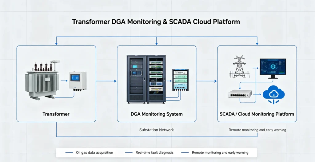
The transformer gas monitoring system can transmit gas concentrations, alarms, diagnostic results, and system status to the substation SCADA or plant monitoring platform. Communication supports Modbus, IEC 61850, Ethernet, and RS485 (subject to actual device support), forming a complete closed loop:
Transformer → Oil Sampling → Gas Extraction → Gas Detection → Data Processing → Fault Diagnosis → Alarm → SCADA
Transformer DGA Monitoring System Architecture
The system architecture is as follows:
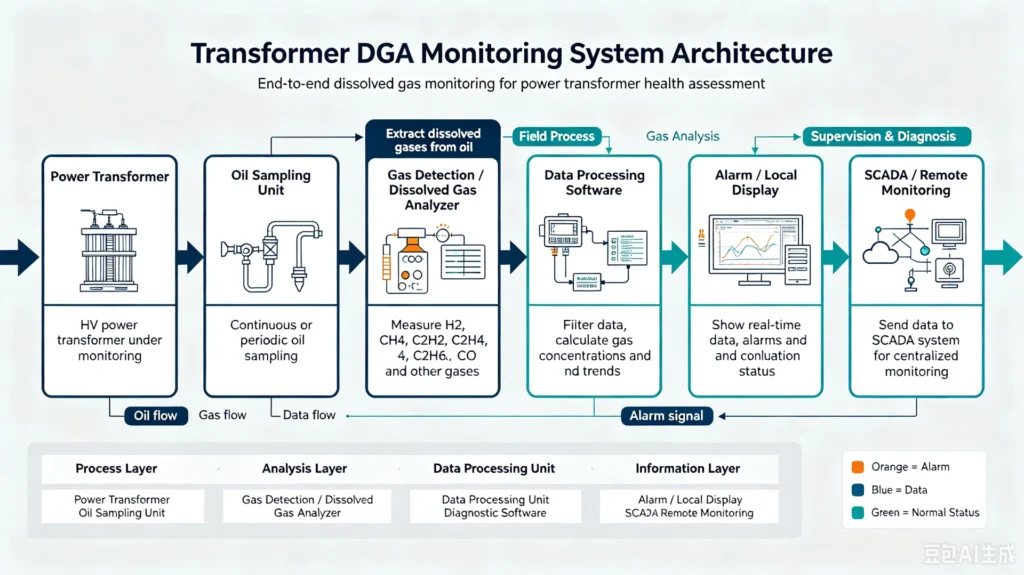
Working Principle describes the dynamic process; System Architecture describes the system composition. The two should be presented separately.
Key Components of a DGA Monitoring System
| Component | Function |
|---|---|
| Oil Sampling Unit | Obtains representative transformer oil |
| Gas Extraction Unit | Separates dissolved gases from oil |
| Gas Detection Unit | Measures target gases |
| Data Processing Unit | Processes and stores measurement data |
| Diagnostic Module | Evaluates gas patterns and trends |
| Communication Module | Sends data to SCADA |
| Alarm Module | Generates warning and alarm signals |
Online DGA System vs. Laboratory DGA Testing
Online monitoring and laboratory testing are complementary in power asset management, with obvious differences in monitoring logic and application scenarios.
| Monitoring Dimension | Online DGA System | Laboratory DGA Testing |
|---|---|---|
| Oil Sampling Mode | Automatic, continuous, unattended | Manual, periodic sampling |
| Measurement Frequency | 24/7 continuous or high-frequency intermittent detection | Quarterly/annual periodic detection |
| Data Timeliness | Near real-time data output | Data obtained after laboratory analysis (time lag) |
| Trend Monitoring | Full-cycle continuous trend tracking | Discrete trend judgment based on historical sampling points |
| Alarm Function | Automatic hierarchical alarm output | Manual analysis and judgment, no automatic alarm |
| Remote Access | Full remote data viewing and management | Limited remote data query capability |
| On-Site Labor Cost | Extremely low | High (sampling, delivery, testing required) |
Conclusion: Online DGA systems are suitable for long-term continuous condition monitoring of key transformers, while laboratory testing is still irreplaceable for periodic verification and in-depth fault diagnosis.
Why Is Online DGA Monitoring Used?
Online DGA monitoring is used to provide continuous, real-time insight into transformer condition without relying solely on periodic laboratory sampling. By continuously measuring dissolved gases and moisture, it enables trend monitoring and early warning of developing faults such as overheating, partial discharge, and insulation deterioration. This allows operators to detect abnormal gas generation at an early stage, reduce manual sampling frequency, and make timely, data-driven maintenance decisions.
FAQ
How does a transformer DGA monitoring system work?
A transformer DGA monitoring system continuously samples transformer oil through a closed-loop path, separates dissolved gases via vacuum bubbling, measures key fault gas concentrations, processes the data, and applies diagnostic models to identify developing faults. Results are transmitted to SCADA or monitoring platforms for early warning and maintenance decision-making.
What gases does an online DGA monitoring system measure?
It typically measures H₂, CH₄, C₂H₆, C₂H₄, C₂H₂, CO, CO₂, O₂, and N₂, plus moisture — covering the key fault gases used for comprehensive transformer condition assessment.
How does a transformer dissolved gas analyzer detect dissolved gases?
The transformer dissolved gas analyzer first separates dissolved gases from the oil, then measures gas concentrations using detection technology such as photoacoustic spectroscopy. Different gases are associated with different fault types, such as H₂ with partial discharge and C₂H₂ with arcing.
How often does an online DGA system sample transformer oil?
Sampling is continuous or near-continuous, depending on system design. Unlike periodic laboratory testing, an online DGA system provides uninterrupted trend visibility and real-time data under actual operating conditions.
Can online DGA detect transformer faults automatically?
Yes. The built-in edge diagnosis engine applies industry-standard models such as the improved Duval Triangle and Three-Ratio Method to automatically analyze gas concentrations and trends, output probability evaluations of fault types, and trigger multi-level alarms when thresholds are exceeded.
What is the difference between online DGA and laboratory DGA testing?
Laboratory DGA testing is periodic and manual, providing only a snapshot at the time of sampling. Online DGA monitoring is continuous and automated, delivering real-time data, trend tracking, and early fault warnings without frequent manual sampling. The two are often complementary: online monitoring for continuous surveillance, laboratory testing for final verification and in-depth analysis.
Conclusion
The complete working logic of a transformer DGA monitoring system forms a reliable predictive maintenance closed loop:
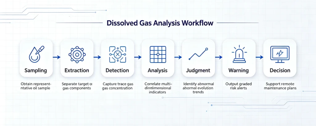
Transformer Oil Sampling → Dissolved Gas Extraction → Precision Gas Detection → Multi-Dimensional Data Analysis → Fault Trend Judgment → Hierarchical Early Warning → Remote Monitoring & Maintenance Decision.
This equipment converts invisible internal transformer fault information into quantifiable real-time data, helping global power utilities and EPC project teams realize refined transformer asset management, effectively reduce unplanned outage risks, and improve the overall safety and stability of power system operation.
Technical Reference & Data Sources
This article complies with international power industry standards, with all technical principles, fault judgment rules and parameter specifications derived from the following authoritative documents:
- IEC 60599: Mineral oil-impregnated electrical equipment in service – Guide to the interpretation of dissolved and free gases analysis
- IEEE C57.104-2019: Guide for the Interpretation of Gases Generated in Mineral Oil-Immersed Transformers
- IEC 60567: Oil-filled electrical equipment – Sampling of gases and analysis of free and dissolved gases
- IEC 61181: DGA testing specifications for factory and field application of oil-immersed power equipment
- IEEE C57.106: Standard Guide for Acceptance and Monitoring of Mineral Oil Used in Electrical Equipment
CTA: Looking for a high-stability transformer online DGA monitoring system for your substation or power project? Browse our Transformer DGA Online Monitoring System product page for detailed parameters, project cases and customized solution support.