Leave your message

-
Leon Zhang sales consultant
-
Email: zxl635973785@gmail.com
-
Phone/WhatsApp/Wechat: +86 13655813266

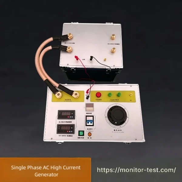
HF-HG-309 Single Phase AC High Current Generator
Single Phase AC High Current Generator provides stepless adjustable high alternating test current. It is widely adopted for temperature rise tests and current load tests of switches, current transformers and other low-voltage electrical apparatus in power industry.
Send your requirements, we will quote for you within 12 hours
This three-phase voltage and current test source is capable of outputting continuously adjustable AC voltage and current. It supports independent voltage output, independent current output and synchronous output of voltage and current. It can simulate phase loss and three-phase unbalance conditions, and is widely applied to characteristic tests of protective relays and related electrical equipment in power systems.
Main Technical Parameters
| Item | Specification |
|---|---|
| Input Power | AC 220 V |
| Output Current | AC 0~1000 A |
| Output Voltage | AC 0~380 V |
Operating Procedures
-
Before switching on power, turn off the Power Control switch, and turn knobs for Phase A Voltage & Current, Phase B Voltage & Current, Phase C Voltage & Current counterclockwise back to zero position.
-
Switch on power. Connect A, B, C, N terminals of Power Input to three-phase four-wire power supply. Link A/B/C Current Output terminals, A/B/C Voltage Output terminals and Active Contact Input terminals to relay contacts using dedicated test leads.
-
Current output test: After wiring, close Power Control switch and press Start button. Adjust Phase A / B / C knobs clockwise to set required test current. Press Stop then Start again to conduct characteristic test on equipment under test.
-
Voltage output test: After wiring, close Power Control switch and press Start button. Adjust Phase A / B / C knobs clockwise to set required test voltage. Press Stop then Start again to conduct characteristic test on equipment under test.
-
Simultaneous voltage & current output: After wiring, close Power Control switch and press Start button. Adjust Phase A / B / C knobs clockwise to set test voltage and test current sequentially. Press Stop then Start again to conduct characteristic test on equipment under test.
-
For phase loss or three-phase unbalance simulation: Disconnect one phase or turn the corresponding knob back to zero.
-
If only 220 V single-phase supply is available: Short-circuit Phase A and Phase B inputs for live wire, connect equipment N terminal to neutral wire. Other operations follow Step 1, 2, 3, 4 above.
-
When used as three-phase voltage & current source: Short-circuit Normally Open contact of switch input before pressing Start button. No output if Normally Closed contact is shorted instead.
Precautions
- Inspect cross-section and length of current output cables before operation; improper wiring will affect actual output current.
- Turn all three-phase current adjustment knobs counterclockwise back to zero after each use.
- Operate strictly in accordance with this manual after purchase.
- Handle with care during transportation; avoid severe vibration.
- Storage environment: Temperature 0~30℃, relative humidity ≤85%. Ambient air must be free from corrosive contaminants.
FAQ | Three-phase Voltage and Current Test Source
Q1: What is this test source mainly used for?
A: It outputs adjustable three-phase AC voltage and current to conduct characteristic tests for protective relays. It can simulate phase loss and three-phase unbalance faults.
Q2: What is the power supply requirement for the device?
A: Standard input power is AC 220 V. It supports single-phase power supply for field use under specific wiring methods.
Q3: Can voltage and current be output at the same time?
A: Yes. It supports independent voltage output, independent current output and synchronous output of voltage and current for comprehensive relay testing.
Q4: How to simulate phase loss or three-phase unbalance conditions?
A: Disconnect one phase circuit or turn the corresponding adjustment knob back to zero to realize phase loss and unbalance simulation.
Q5: Why is the actual output current lower than the set value?
A: It is usually caused by insufficient cross-section or excessive length of output cables. Please use suitable short thick connecting wires.
Q6: What operation should be done after testing?
A: Turn all adjustment knobs counterclockwise back to zero position before cutting off the power supply.
Q7: Can the equipment work as a three-phase current and voltage source directly?
A: Yes. Short-circuit the normally open contact of the switching input; there will be no output if the normally closed contact is shorted.
Q8: What are the requirements for equipment storage?
A: Store in an environment of 0~30℃ with relative humidity ≤85%, and keep away from corrosive gas.

Reviews
There are no reviews yet.