

A megohmmeter is a portable instrument that applies a stabilised direct voltage to insulation and measures the resulting resistance, reported in megohms or gigohms, so that moisture, contamination and cracked insulation become visible long before they turn into a flashover. It is the least glamorous instrument in a maintenance workshop and the one that decides, most often, whether a motor is put back in service or pulled for rewind.
Author: Leon Zhang — Power monitoring and testing equipment team, Baoding Houfeng Trading Co., Ltd., specifying insulation test sets for plants, contractors and service workshops
Technical review: this guide passed editorial review and was checked against IEC 61557-2:2019, IEEE 43-2013 and IEC 61010-2-034:2017 before publication
Last updated: 21 October 2026
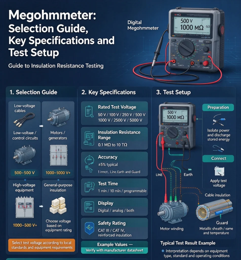
Key takeaways
- A megohmmeter is judged by the stability of its test voltage under load, not by the highest resistance it can print; an instrument that drops voltage on a wet winding reports a number that no standard recognises.
- Four ranges cover almost every job: 250 V for control wiring, 500 V for low voltage machines, 1 kV for medium voltage equipment and 5 kV or 10 kV for large stator windings and long cables.
- Conversion from analog megohmmeter to digital is not cosmetic; the digital types record dielectric absorption ratio, polarisation index and step voltage sequences that a hand-cranked instrument cannot reproduce consistently.
- The reading alone decides nothing. It becomes a diagnosis only after temperature correction, comparison against a recorded baseline and a look at how the value moves between one minute and ten.
- The most common application is condition checking of compressor motors and chiller plant, where a dropped phase-to-ground reading in the megohm range precedes a nuisance trip by weeks.
- Accessories matter as much as the instrument: guarded leads, a discharge path and a calibration certificate decide whether the measurement is defensible.
Introduction
It is treated as a commodity item and specified in a hurry, which is why so many plants end up with an instrument whose readings nobody can defend three years later. On a medium voltage stator the resistance value is quoted in gigohms and the difference between 40 GΩ and 8 GΩ across two annual tests is the whole diagnosis, while the same instrument pointed at a 400 V motor terminal box answers a much simpler question about whether it is safe to energise.
This guide is written for the person who has to choose the instrument and then defend its readings, not for the designer of the measuring circuit. It covers how an insulation tester differs from a multimeter, how the test voltage and resistance range should be matched to the equipment being tested, what the readings actually mean once temperature and time are accounted for, and where the common uses sit in a plant maintenance programme. Selection tables are given in the form a procurement engineer can send to a supplier, and every threshold quoted here is traceable to a published clause rather than to workshop folklore.
What an insulation tester measures that a multimeter cannot
A multimeter measures resistance with a few volts across the probes, which is enough to find an open circuit and useless for finding insulation that is wet, and this is the whole reason a separate instrument exists: the same surface film can read orders of magnitude lower at 9 V than it does at the 500 V a service test applies (IEC 61557-2:2019), Insulation that behaves as a few megohms at 9 V may behave as a few hundred kilohms at 500 V, because the higher stress drives leakage paths through moisture and surface contamination that a low test voltage simply does not excite.
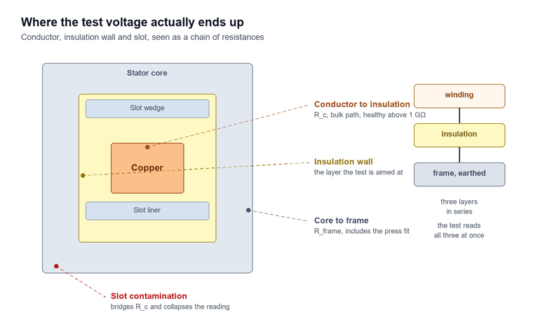
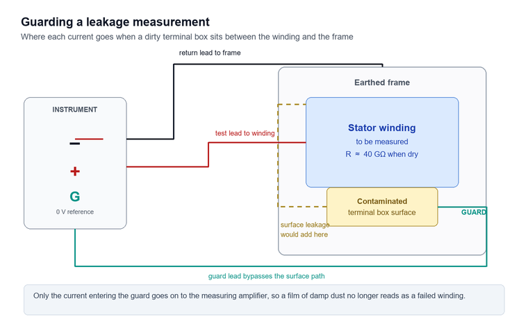
The instrument has to do two things at once. It generates a direct voltage in the hundreds or thousands of volts, and it measures a current in the nanoampere to microampere region while doing so. Resistance follows from Ohm’s law. A reading of 100 MΩ at 500 V corresponds to a leakage current of 5 µA, which is why guarding and shielding are not optional accessories but part of the measurement itself.
There is a second difference that matters more in practice. Insulation is not a resistor. It behaves as a capacitance in parallel with a resistance, and that capacitance absorbs charge for seconds after the voltage is applied. The apparent resistance therefore climbs with time. A multimeter takes a reading in milliseconds and reports the absorption current as if it were resistance. A proper instrument holds the voltage, waits, and reports the value at a defined moment.
The three currents inside one reading
- Capacitive charging current falls to near zero within a few seconds and depends on the physical size of the winding or cable.
- Absorption current decays over tens of seconds as polar molecules inside the insulation align with the field, and its decay rate is the diagnostic signal that dielectric absorption ratio and polarisation index are built on.
- Leakage current is the steady component that moisture, carbon tracking and contamination increase, and it is the part the acceptance thresholds are written against.
Only the third component describes the health of the insulation, but the instrument measures all three together. The same absorption behaviour explains why a partial discharge monitoring programme reads a different signature on the same winding, and the two methods are used together rather than instead of one another. That is why a fifteen-second spot reading and a ten-minute polarisation test can disagree about the same winding without either instrument being wrong.
Test voltage and range: matching instrument to insulation
Test voltage is chosen from the rated voltage of the equipment under test rather than from the convenience of the instrument, and this single rule eliminates most of the arguments that arise when a reading is disputed. IEC 61557-2:2019 sets the requirements for insulation resistance measuring equipment up to 1 000 V AC and 1 500 V DC distribution systems, while IEEE 43-2013 gives the test voltage ladder for rotating machine windings rated 750 W and above.
The logic behind the ladder is that a test voltage far below the operating stress will not reveal the defects that matter, and a test voltage above the insulation’s design stress can leave a weak spot worse than it found it. For a 400 V motor, 500 V DC is the customary choice and 1 000 V DC is acceptable for a clean, dry winding. For a 6.6 kV stator the working range is 2 500 V to 5 000 V DC, and for a long 11 kV cable run a 5 kV instrument is the practical minimum because the capacitance of the cable takes a long time to charge at lower voltage and the reading drifts while it does.
Resistance range matters as much as voltage range, and it is the specification most often misread. A 10 GΩ top range on a hand-held instrument sounds generous until it is used on a dry 6.6 kV stator that reads beyond the top of the scale, at which point the actual value is unknown and the only useful information is that it exceeded the range. Instruments with a 200 GΩ or 2 TΩ top range cost more and are worth it for generators and large machines, where the interesting comparison is between 40 GΩ this year and 8 GΩ last year.
Selection matrix for common duties
| Equipment | Rated voltage | Test voltage | Useful top range | Reading that warrants attention |
|---|---|---|---|---|
| Control and instrument wiring, such as a 24 V solenoid circuit | 24 to 230 V | 250 V | 2 GΩ | Below 1 MΩ |
| Low voltage motor, 400 V | 400 V | 500 V | 5 GΩ | Below 1 MΩ, or below half the baseline |
| Low voltage switchboard busbar | 400 to 690 V | 500 V to 1 kV | 10 GΩ | Below 1 MΩ |
| Medium voltage motor, 3.3 to 6.6 kV | 3.3 to 6.6 kV | 1 kV to 2.5 kV | 100 GΩ | Below kV + 1 in MΩ at 40 °C |
| Large stator winding, 6.6 kV and above | 6.6 to 13.8 kV | 2.5 kV to 5 kV | 1 TΩ | Polarisation index below 1.5 |
| Medium voltage cable, 11 to 33 kV | 11 to 33 kV | 5 kV | 1 TΩ | Falling trend between annual tests |
| Surge arrester and bushing | 11 to 220 kV | 2.5 kV to 5 kV | 1 TΩ | Any step change from the recorded value |
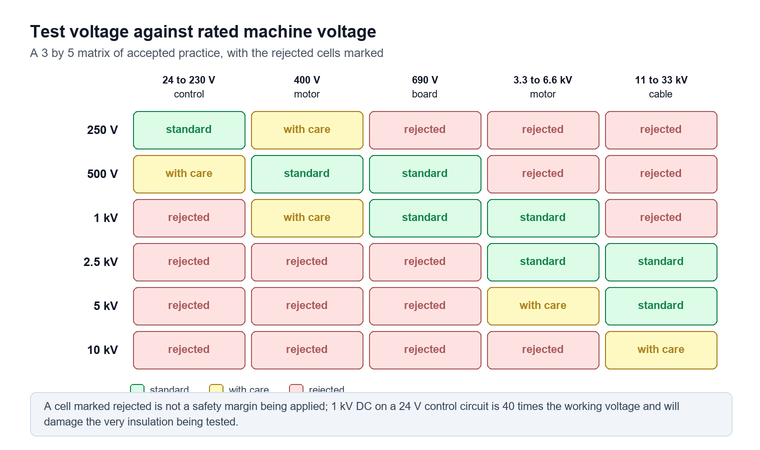
Two entries in that table deserve a note. The kV + 1 figure is the minimum insulation resistance in megohms recommended by IEEE 43-2013 for form-wound stators and DC armatures at a reference temperature of 40 °C, so a 6.6 kV machine is expected to stay above 7.6 MΩ once corrected. The second is that a 250 V range is genuinely useful and not a marketing extra: applying 1 kV to 24 V control wiring is a good way to destroy the very insulation being tested.
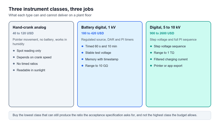
Analog versus digital: what actually changes
An analog megohmmeter shows resistance on a moving-coil movement driven by a hand crank or a small generator, and it survives conditions that kill electronics, which is why it is still specified for field work in humid climates. The instrument is mechanically simple, needs no battery, and its pointer movement gives an immediate sense of how fast the reading is climbing, which is information a digital display hides behind a settling number.
The limitation is repeatability. A hand crank has to be turned at a steady speed to hold the test voltage steady, and the resistance indicated depends on that voltage. Two technicians testing the same winding on the same afternoon can produce readings a factor of two apart without either of them doing anything wrong. For a go or no-go check on a 400 V motor this is acceptable. For a polarisation index, a step voltage test or a trend record that will be compared across five years, it is not.
The digital types removed the crank and added the functions that the standards actually describe. These include a timed one-minute and ten-minute reading for the polarisation index, a fifteen-second and sixty-second reading for the dielectric absorption ratio, and a step voltage sequence. Many models also store the result with a timestamp. Some also apply a filter that suppresses the capacitive charging current, which shortens the settling time on long cable runs from minutes to seconds.
The practical difference shows up in the report. An analog reading gives one number and a technician’s note. A digital instrument gives a sequence. That sequence is what separates absorbed moisture from a genuinely dry winding. Buying analog for a workshop that has to justify its decisions to an insurer or a plant owner is a false economy; buying digital for a crew that only ever checks 400 V motors is an unnecessary one.
Where each type still wins
| Criterion | Analog megohmmeter | Digital insulation tester | Who should care |
|---|---|---|---|
| Test voltage stability | Depends on crank speed | Regulated | Anyone recording trends |
| Battery dependence | None | Rechargeable pack | Remote sites without power |
| Timed readings for polarisation index | Manual stopwatch | Built in | Machine condition monitoring |
| Step voltage sequence | Not available | Standard on most models | Medium voltage acceptance testing |
| Cost of entry | Lowest | Two to four times analog | Contractors doing spot checks |
| Readout under strong sunlight | Pointer, readable | Some LCDs wash out | Outdoor substation work |
| Survives a drop onto concrete | Usually | Depends on the housing | Site crews |
Megohmmeter uses across the maintenance programme
The instrument earns its place in four different routines, and the reading is interpreted differently in each, which is why a single threshold copied from a datasheet causes so much confusion. The first is acceptance testing of new or rewound equipment, where the value has to clear a published minimum before the machine is energised at all. The second is periodic condition monitoring, where the absolute value matters far less than its movement against a baseline recorded under the same conditions.
The third is fault finding after a trip, where the question is not whether the insulation is good but where the fault is, and the answer comes from sectionalising: disconnecting the cable from the motor, testing each half separately and watching which section carries the low reading. The fourth is pre-work safety verification, where a reading near zero is the confirmation that a circuit has been isolated and discharged and is safe to touch, and this is the only routine in which a low reading is the good outcome.
Mixing these four up produces most of the arguments that insulation testing attracts, and the same pattern repeats in oil analysis, where the online DGA monitoring system selection guide makes the identical baseline-versus-threshold distinction. A 400 V motor reading 3 MΩ at 30 °C passes an acceptance test comfortably, and the same 3 MΩ measurement taken six months into a monitoring programme on a machine whose baseline was 800 MΩ is a warning of the first order. The number is identical; the question being asked is not.
Sectionalising a low reading on a motor feeder
- Isolate, lock off and prove dead at the motor terminals rather than at the starter.
- Disconnect the supply cable from the motor and test the cable alone with the far end isolated.
- Test the motor alone, winding to frame, with the cable disconnected so that its capacitance does not distort the settling time.
- On a three-phase winding, test each phase to earth separately and then phase to phase, which distinguishes a single grounded coil from a general damp condition.
- Discharge each winding to earth through the instrument’s discharge path before touching any terminal, and confirm the voltage has gone with a proved detector.
Phase-to-phase readings on a healthy three-phase winding normally sit a little lower than phase-to-earth readings, because the test voltage now stresses two insulation systems in series. A phase pair that reads markedly lower than its neighbours points to damage between adjacent coils in the same slot, which a single phase-to-earth test would never show.
Insulation resistance test: compressor motor and chiller maintenance
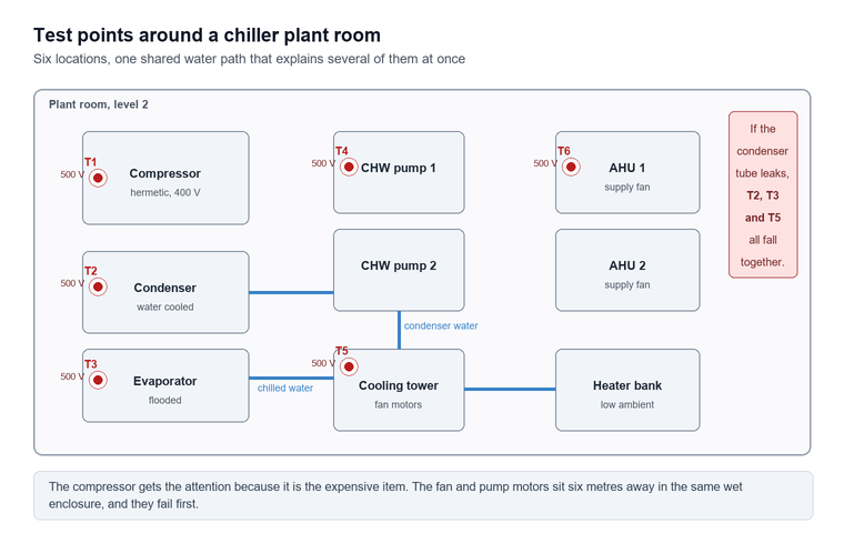
The routine that plant engineers describe as the megohmmeter insulation resistance test compressor motor chiller maintenance job is the highest-value test in most industrial programmes, because refrigerant circuits and cooling water circuits both find ways to put moisture where moisture should never be. Hermetic and semi-hermetic compressors are especially exposed. The motor winding sits inside the refrigerant envelope, so a slow refrigerant leak or a flooded evaporator deposits condensate directly onto it. So does a chiller that has stood idle through a humid shutdown season.
The test is short and the interpretation is where the value lies. Isolate the compressor at the local isolator, lock off, prove dead, and discharge the winding through the instrument before connecting. Then apply 500 V DC from winding to the compressor body, hold for sixty seconds, and record the value together with the winding temperature. A worked example makes the sequence concrete. For example, a 55 kW semi-hermetic compressor that has stood idle since October is tested in March at 18 °C and reads 210 MΩ. Corrected to 40 °C on the thermosetting curve the value is roughly 168 MΩ, well above any acceptance floor, and the ten-minute polarisation index comes out at 3.1. The machine is dry enough to start. Had the index come out at 1.2 with the same corrected resistance, the decision would have been to dry the winding out with gentle heat and test again before anyone closed the isolator.
On a semi-hermetic machine the terminal block should be opened and inspected before the test, because a carbonised terminal cluster produces exactly the same reading as a damp winding and costs nothing to rule out.
Chillers add a second insulation system that is often forgotten. It covers the condenser and evaporator fan motors, the pumps on the chilled water loop and the electric heaters on any low ambient package. Water-cooled condensers are the usual source of trouble, because a tube-to-tube-plate leak puts cooling water onto a terminal box that nobody inspects between annual services. A single low reading on a fan motor in the same enclosure as a leaking condenser is a strong hint that the problem is shared.
Seasonal test schedule for a chiller plant
| Month | What is tested | Test voltage | Why now |
|---|---|---|---|
| Before seasonal start | Compressor winding, terminal block inspection | 500 V | Moisture accumulates during the idle season |
| Before seasonal start | Condenser and evaporator fan motors | 500 V | Same enclosure as the compressor |
| Mid season | Chilled water pump motors | 500 V | Wet rotor and seal leakage show up under load |
| Mid season | Compressor winding on packaged units | 500 V | Refrigerant leak detection window |
| After any leak repair | Repaired circuit and adjacent windings | 500 V | Brazing heat and moisture ingress both affect insulation |
| Shutdown | Full plant, recorded for next year’s baseline | 500 V | Establishes the comparison for the start-up test |
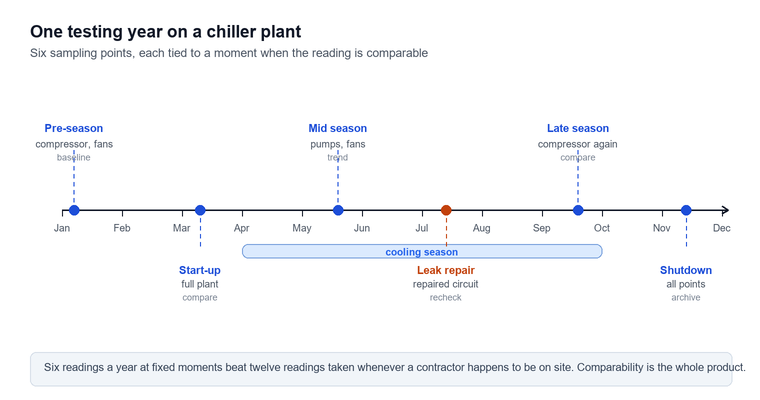
The schedule is deliberately light on test points and heavy on timing. A chiller that is tested at the right moment in its seasonal cycle gives a usable trend after two years; one that is tested opportunistically whenever a contractor happens to be on site gives a scatter of numbers that cannot be compared with anything.
Reading the number: temperature, time and trend
A raw resistance figure means almost nothing until three corrections have been applied, and skipping any one of them is how a sound machine gets pulled from service and a failing one stays in it. The first correction is temperature: insulation resistance falls roughly by half for every 10 °C rise (IEEE 43-2013), which means a winding measured 40 °C below reference can read four times its true corrected value (IEEE 43-2013 Table 2 factors), so a cold Monday morning reading and a Friday afternoon reading of the same machine can differ by a factor of four with no change in condition.
The temperature correction factor is the multiplier that converts a reading taken at winding temperature to the value it would have produced at the 40 °C reference that IEEE 43-2013 adopts. For thermoplastic insulation the factor is the simple halving rule. For modern thermosetting insulation it is a gentler curve, with a factor of 0.7 at 10 °C and 2.3 at 60 °C. Applying the thermoplastic curve to an epoxy winding over-corrects by a wide margin and makes a healthy machine look marginal.
The second correction is time. A reading taken fifteen seconds after the voltage is applied is dominated by charging and absorption current, and a reading at sixty seconds is the conventional spot value that the standards’ minima refer to. The third is the comparison itself: against a published minimum for acceptance, and against a recorded baseline for condition. Both are needed, and neither substitutes for the other.
Absorption ratios and their thresholds
| Ratio | Readings used | Healthy value | What a low value indicates |
|---|---|---|---|
| Dielectric absorption ratio | 60 s divided by 15 s | Above 1.4 for most windings | Surface contamination, moisture film |
| Polarisation index | 10 min divided by 1 min | Above 2.0 for class B and above | Absorbed moisture in the bulk insulation |
| Polarisation index, older windings | 10 min divided by 1 min | Above 1.5 | Acceptable for aged insulation |
| Polarisation index, suspicious high | 10 min divided by 1 min | Above 8 on old asphaltic insulation | Dry and brittle, mechanically at risk |
The polarisation index is the ratio of the ten-minute reading to the one-minute reading, and a value below the threshold with a dielectric absorption ratio that stays acceptable is the classic signature of moisture absorbed into the bulk insulation rather than lying on its surface. The reverse combination, a normal index with a depressed ratio, points to a dirty or contaminated surface path that a guard terminal and a proper cleaning will often resolve without any rewind decision being needed.
Limitations and boundaries
This guide covers portable insulation resistance measurement on de-energised equipment at test voltages from 250 V to 10 kV, and five limitations mark where its advice stops being safe to follow without further reading.
The first limitation is that an insulation resistance test cannot measure dielectric strength. A winding reading 20 GΩ may still break down at twice rated voltage, and a winding reading 200 MΩ may withstand a full overvoltage test without distress. The measurement describes leakage, not the voltage at which the insulation fails, and no amount of resistance reading substitutes for a withstand test where the standard requires one.
The second is that the test cannot locate the defect. A low reading tells you that something is wrong somewhere on the connected circuit, and separating a damp terminal block from a punctured coil requires disconnection, sectionalising and often a surge comparison test. Reading a number and declaring a winding failed is the most common way this instrument is misused.
The third is that below the dew point the measurement is not valid at all. Condensation on a cold winding produces a surface leakage current that has nothing to do with insulation condition, and the temperature correction factors in IEEE 43-2013 do not apply to it, because they were derived on clean dry specimens. Warm the winding above the dew point or record the result as indicative only.
The fourth is that the instrument itself needs a current calibration certificate and a functional check. A lead with a nick in its insulation, a guard terminal left unconnected or an ageing internal high voltage source produces a wrong reading with complete confidence, and neither the instrument nor the operator will show any sign of it. A check against a known high value resistor before each campaign costs a minute.
The fifth is cost against benefit. A 10 kV tester with a 2 TΩ range and full step voltage capability costs several times a 1 kV hand-held unit, and for a contractor whose work is entirely 400 V distribution boards the extra capability is dead weight, while for a generator overhaul shop the cheaper instrument cannot produce the readings the acceptance specification asks for.
Frequently asked questions
The seven questions below are the ones that come up most often when an instrument is being specified or a reading is being disputed, and each answer stands on its own without requiring the rest of the guide.
What test voltage should I use on a 400 V motor?
Use 500 V DC for a routine check and 1 000 V DC only on a winding that is known to be clean and dry. The test voltage is chosen from the machine’s rated voltage rather than from the instrument’s highest setting, and applying several kilovolts to a low voltage winding risks turning a marginal defect into a failure. Record the voltage used alongside the reading, because values taken at different voltages are not directly comparable.
Why does my reading keep climbing while I watch it?
The winding is charging. Insulation behaves as a capacitor in parallel with a resistor, and the absorption current decays over tens of seconds, so the apparent resistance rises until that current becomes negligible. This is normal and is the basis of the dielectric absorption and polarisation ratios. A reading that never settles, or that settles in under two seconds on a large machine, is more suspicious than one that climbs slowly.
Can I test a motor while it is still connected to the drive?
Only if the drive and the supply cable are completely disconnected from the winding, and never with a variable frequency drive left in circuit. The test voltage will be applied to the drive output stage, and the drive’s own filter capacitors will distort the reading even if nothing is damaged. Isolate at the motor terminals, prove dead, discharge the winding, and test the motor alone; test the cable separately if the cable condition is in question.
Is a 1 000 V megohmmeter enough for medium voltage work?
No. A 6.6 kV stator needs 2 500 V to 5 000 V DC to stress the insulation in a way that resembles service conditions, and a 1 kV instrument will report a healthy-looking value on a winding that a proper test would condemn. The correct choice for medium voltage equipment is a 5 kV instrument, with 10 kV reserved for large machines and long cable runs where the specification asks for it.
Do I need a calibration certificate for a megohmmeter?
Yes, if the reading is used to make an engineering decision that anyone else will rely on. An insulation tester that has drifted reads high or low with no outward sign, and a certificate with a traceable chain of comparison is the only defence when a test result is challenged after an equipment failure. Annual calibration is the usual interval, with a functional check against a known resistor before each testing campaign.
What does a reading of zero actually mean?
It means the resistance is below the instrument’s lowest range, which on most testers is somewhere under 100 kΩ, and it almost always means a hard short rather than damp insulation. Test again with the circuit sectionalised before condemning anything, because a shorted capacitor, a closed contactor held in by a control fault or a connected indicator lamp will all produce a zero reading on a perfectly sound winding.
How often should a plant test its equipment?
Set the interval from the consequence of failure and from the observed trend rather than from a fixed calendar. Critical motors and chillers tested annually give a usable baseline after two cycles; standby equipment that only runs during an outage needs a test before each start because it sits idle in the conditions that cause the most moisture ingress. Once a trend exists, lengthen the interval for stable machines and shorten it for any machine whose reading has moved.
Conclusion
The instrument itself is one of the simplest pieces of test gear in a workshop, and almost every dispute about it comes down to three things that have nothing to do with the meter: the test voltage was chosen wrongly, the temperature was not recorded, or the reading was compared against a threshold instead of against a baseline. Get those three right and even a modest 500 V unit produces decisions that hold up years later.
For anyone buying, the practical sequence is to fix the highest rated voltage that will be tested, choose an instrument whose top resistance range is at least two decades above the values expected on that equipment, and insist on timed readings if any machine in the fleet will ever need a polarisation index. Accessories, calibration and a discharge path belong in the same purchase order as the instrument, because a tester without them is a number generator rather than a measuring system.
Baoding Houfeng supplies insulation resistance testers, calibrators and the high voltage test sets that follow an insulation test in an acceptance sequence. For most plants the practical way to buy a megohmmeter is to match the top test voltage to the highest rated machine in the fleet and take the resistance range from there. The full range sits under the high voltage tester category page, with individual instruments listed on the digital insulation resistance meter, insulation resistance tester and insulation resistance tester calibrator pages. Company background and the team behind these guides are on the about us page. For a fleet that mixes low voltage boards with medium voltage machines, contact us with the equipment list and we will tell you which combination of ranges covers it without buying capacity that will never be used.
References and technical sources
- IEC 61557-2:2019, Electrical safety in low voltage distribution systems up to 1 000 V AC and 1 500 V DC — Equipment for testing, measuring or monitoring of protective measures — Part 2: Insulation resistance, edition 3.0, International Electrotechnical Commission, 2019. webstore.iec.ch/en/publication/60892
- IEEE 43-2013, IEEE Recommended Practice for Testing Insulation Resistance of Electric Machinery, IEEE Power and Energy Society, 2014. standards.ieee.org/ieee/43/11045
- IEC 61010-2-034:2017, Safety requirements for electrical equipment for measurement, control, and laboratory use — Part 2-034: Particular requirements for measurement equipment for insulation resistance and test equipment for electric strength, International Electrotechnical Commission, 2017. webstore.iec.ch
- IEC 60034-27-1:2017, Rotating electrical machines — Part 27-1: Off-line partial discharge measurements on the stator winding insulation of rotating electrical machines, International Electrotechnical Commission, 2017. webstore.iec.ch
- DOE Motor System Market Assessment, Improving Motor and Drive System Performance: A Sourcebook for Industry, U.S. Department of Energy, Advanced Manufacturing Office. energy.gov
- ANSI/NETA ATS-2023, Standard for Acceptance Testing Specifications for Electrical Power Equipment and Systems, InterNational Electrical Testing Association, which defers acceptance criteria for rotating machines to IEEE 43-2013. netaworld.org
- IEEE 95-2002, IEEE Recommended Practice for Testing Insulation Resistance of Rotating Machinery, IEEE Standards Association. standards.ieee.org