

What Is a Transformer Partial Discharge Monitoring Device?
A transformer partial discharge monitoring device is a dedicated electrical condition monitoring system designed to detect, quantify, and track partial discharge activity within transformer insulation systems. Unlike general electrical testing tools, it focuses specifically on insulation defect early warning rather than routine electrical parameter measurement.
Compliant with IEC 60270 and IEEE C57.113-2023 industry standards, professional transformer PD monitoring systems convert weak PD signals into analyzable data, suppress field background noise, and output intuitive defect assessment results for engineering judgment .
Core Functions of Transformer PD Monitoring Devices
Field-proven transformer partial discharge detection device performs six core practical functions for substation and industrial transformer operation:
- Real-time PD signal detection: Capture transient discharge signals generated by insulation defects inside transformers
- Precise signal acquisition and amplification: Collect weak high-frequency PD signals that cannot be identified by conventional testing equipment
- Intelligent noise filtering: Eliminate substation electromagnetic interference, switching noise, and environmental clutter
- PD characteristic analysis: Calculate discharge magnitude, pulse repetition rate, phase distribution, and trend changes
- Insulation condition assessment: Track insulation aging trends and judge defect severity
- Early alarm and data recording: Trigger threshold alarms and store historical data for maintenance traceability
Detectable Transformer Insulation Problems
A partial discharge monitoring equipment serves as an early warning tool rather than a precise fault positioning instrument. It effectively identifies typical latent insulation defects in oil-immersed and dry-type transformers:
- Internal insulation voids and delamination defects
- Surface creeping discharge on winding and bushing insulation
- Floating electrode discharge caused by loose metal components
- Partial discharge induced by poor internal connection contact
- Progressive aging and deterioration of transformer main insulation
What Are the Main Components of a Transformer PD Monitoring Device?
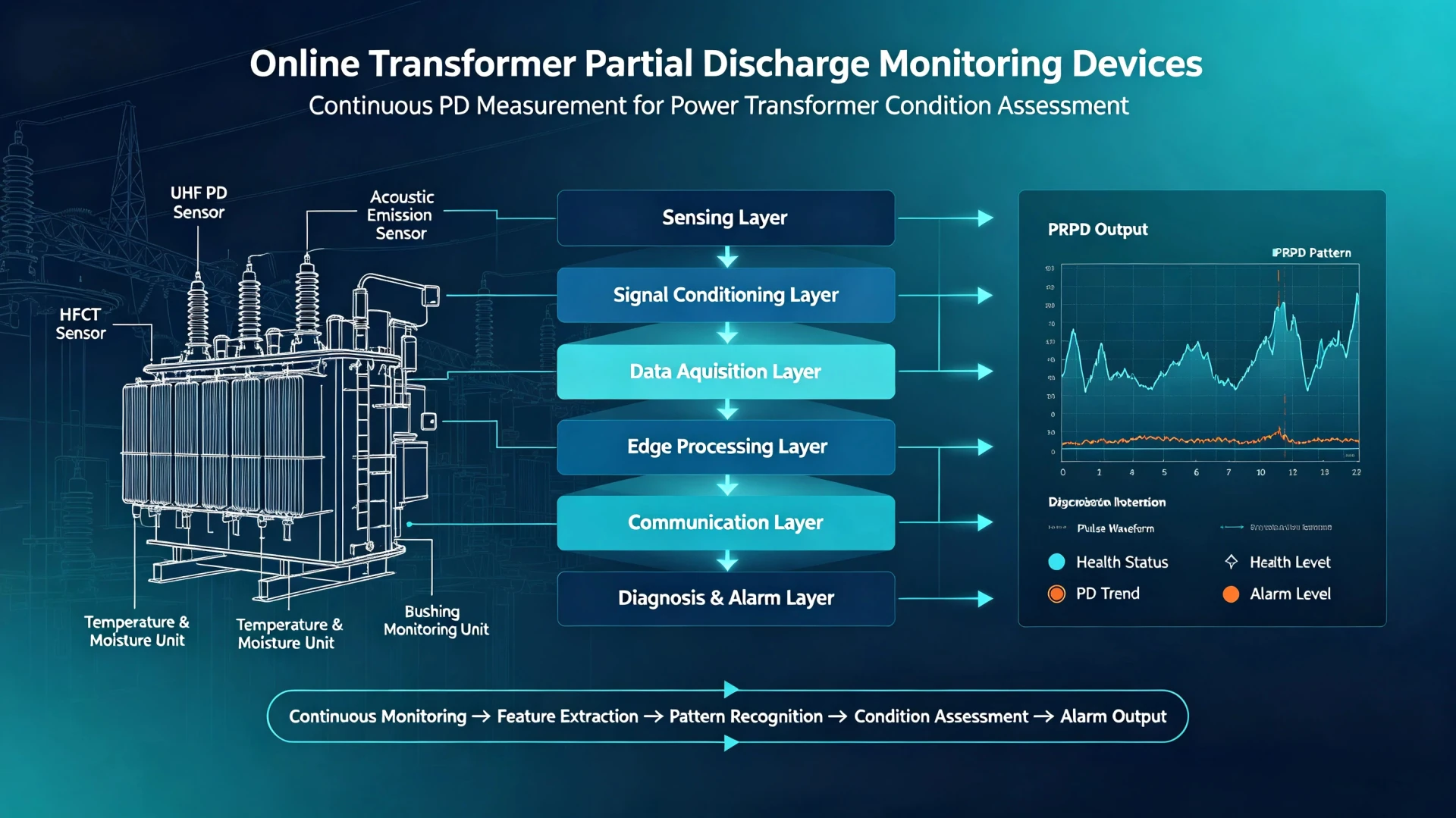
A transformer PD monitoring device is typically built from several functional units that work together to capture, process and present partial discharge data. The exact configuration varies by manufacturer and application, but most systems include the following main components.
1. Partial Discharge Sensors
The sensors are the front end of the monitoring device. They detect PD activity in the transformer insulation and convert it into electrical or acoustic signals for acquisition. Common sensor types used in transformer PD monitoring include:
- HFCT (High-Frequency Current Transformer) — typically clamped around grounding leads or cable shields to pick up high-frequency PD current pulses.
- UHF (Ultra-High-Frequency) sensors — usually installed through inspection ports or drain valves to detect electromagnetic PD emissions in the UHF range.
- AE (Acoustic Emission) sensors — mounted on the transformer tank wall to detect acoustic signals generated by discharge activity.
At the device level, these sensors provide the raw input signals. The question of which sensor type is most suitable for a given transformer belongs to sensor selection and detection strategy, which is covered separately.
2. Signal Acquisition Unit
The signal acquisition unit conditions and digitizes the sensor output. Its main functions include:
- Analog signal acquisition from one or more sensor channels
- Amplification to bring weak PD signals to a measurable level
- Filtering to limit the frequency band and reduce out-of-band interference
- Digitization (A/D conversion) for subsequent digital processing
- Synchronized acquisition, often referenced to the power frequency, so that PD events can be correlated with the AC cycle
This unit determines much of the system’s sensitivity, dynamic range and timing accuracy.
3. Signal Processing Unit
The signal processing unit takes the digitized data and extracts meaningful information. Typical functions include:
- Noise filtering and interference suppression
- Signal classification, for example separating PD pulses from noise or other disturbance sources
- PRPD (Phase-Resolved Partial Discharge) analysis
- Feature extraction, such as pulse amplitude, phase position, repetition rate and pattern characteristics
The output of this unit is the basis for trend analysis and insulation condition assessment.
4. Data Storage and Monitoring Software
This layer manages data, visualization and user interaction. It usually provides:
- Historical data storage for long-term comparison
- Trend curves showing PD activity over time
- PRPD display for pattern-based analysis
- Alarms when preset thresholds or abnormal conditions are met
- Reports for maintenance and engineering records
- Remote access for monitoring and data review
The software is where raw measurements become usable diagnostic information for engineers.
5. Communication Interface
The communication interface connects the monitoring device to substation systems, control centers or cloud platforms. Depending on the actual product configuration, supported protocols may include:
- Ethernet
- Modbus
- IEC 61850
Protocol support should be stated only when the device genuinely provides it. Including protocols that are not implemented would be misleading for both users and search engines.
What Does a Transformer PD Monitoring Device Measure?
| Parameter / Data | Purpose |
|---|---|
| PD signal amplitude | Indicates the relative intensity of detected PD activity |
| PD repetition rate | Shows how frequently discharge events occur |
| PRPD pattern | Shows the phase-related distribution of PD activity |
| PD trend | Tracks changes in discharge activity over time |
| Signal characteristics | Helps analyze detected discharge signals |
| Sensor correlation | Helps distinguish PD signals from interference |
How Does a Transformer PD Monitoring Device Handle Noise?
In a real substation, not every high-frequency signal detected by the sensors is a partial discharge event. Common interference sources include switching operations, radio-frequency interference, corona, grounding noise, vibration and other electrical equipment.
To reduce the influence of these disturbances, a PD monitoring device typically applies several complementary techniques:
- Filtering — limits the frequency band of interest and attenuates out-of-band noise.
- Frequency-domain analysis — separates PD pulses from interference with different spectral characteristics.
- Pattern analysis — uses PRPD patterns to identify phase-correlated PD activity that interference usually does not show.
- Multi-sensor comparison — checks whether a signal appears consistently across channels or only on one, helping identify external interference.
- Signal correlation — verifies whether detected events correlate in time and with the power frequency reference.
Based on these methods, the device applies noise rejection to reduce the influence of interference on measurement results.
The goal is not to completely eliminate noise, but to reduce its influence so that PD data remains reliable enough for trend analysis and insulation condition assessment. Effective noise handling depends on sensor design, acquisition settings, signal processing algorithms and engineering experience, and no single method works in every situation.
What Sensors Can Be Used With a Transformer PD Monitoring Device?
A transformer PD monitoring device can work with different sensor types, depending on the transformer construction, installation conditions and monitoring objectives.
| Sensor | Signal Type | Typical Use |
|---|---|---|
| HFCT | High-frequency current pulse | Detect PD-related current pulses through grounding paths |
| UHF Sensor | Electromagnetic signal | Detect UHF emissions associated with PD inside suitable transformer structures |
| AE Sensor | Acoustic signal | Detect acoustic emissions and support PD source localization |
Different sensors provide complementary information. Sensor selection depends on transformer construction, installation conditions, noise environment and monitoring objectives.
For more on how these sensors are applied in practice, see Transformer Partial Discharge Detection.
Transformer PD Monitoring Device vs Monitoring System
These two terms are related but not identical. A device is the core measurement unit, while a monitoring system is the complete architecture built around it.
| Device | Monitoring System |
|---|---|
| Core measurement / acquisition unit | Complete monitoring architecture |
| Sensors + acquisition + processing | Sensors + acquisition + software + communication + integration |
| Focuses on measurement | Focuses on complete monitoring and data management |
| Can be part of a larger system | Designed for complete application |
A transformer PD monitoring device can be one core component of a complete transformer partial discharge monitoring system.
For the full architecture and system-level view, see Transformer Partial Discharge Monitoring System.
Where Are Transformer PD Monitoring Devices Used?
Transformer PD monitoring devices are used where insulation condition is critical and early detection of PD activity can support better maintenance decisions. Typical applications include:
- Power Transformers — key assets in transmission and distribution networks
- Generator Step-Up Transformers — where failures can directly affect generation availability
- High-Voltage Transformers — operating at voltage levels where insulation stress is significant
- Critical Substation Transformers — where an outage would have major operational consequences
- Aging Transformer Assets — where insulation degradation becomes more likely over time
- Transformers Requiring Continuous Insulation Monitoring — where trend data is needed for ongoing condition assessment
PD monitoring devices are particularly useful where transformer criticality, insulation condition or outage consequences justify additional diagnostic monitoring. They are not automatically required for every high-voltage transformer, but they provide valuable information when the risk profile and maintenance strategy call for it.
How Is a Transformer PD Monitoring Device Installed?
Installation typically follows a structured process, from sensor mounting to final commissioning. The exact procedure depends on the transformer type, sensor configuration and site conditions, but most projects follow these general steps.
Step 1 — Sensor Installation
Sensors are installed according to the selected monitoring scheme. This may include:
- HFCT — clamped around grounding leads or cable shields
- UHF — mounted through inspection ports, drain valves or dedicated openings
- AE — mounted on the transformer tank wall at selected positions
Sensor placement should follow the manufacturer’s instructions and the project’s monitoring objectives.
Step 2 — Signal Connection
Each sensor is connected to the signal acquisition unit using the specified cables and connectors. Cable routing, shielding and grounding should be handled carefully to avoid introducing additional noise.
Step 3 — System Configuration
After connection, the device is configured for the specific application. This typically includes:
- Acquisition parameters
- Active channels
- Alarm thresholds
- Data storage settings
Step 4 — Communication
The device is connected to the local workstation, monitoring platform or SCADA / control system, depending on the actual supported interfaces and protocols.
Step 5 — Commissioning
Commissioning verifies that the system works as intended. Typical checks include:
- Sensor signal response
- Background noise level
- Communication link
- Data acquisition
- Alarm functions
Proper commissioning helps confirm that the device is capturing reliable data and is ready for long-term monitoring.
Key Technical Specifications of a Transformer PD Monitoring Device
| Specification | What It Indicates |
|---|---|
| Sensor Type | Supported sensor types, such as HFCT, UHF or AE |
| Number of Channels | How many sensors or measurement points can be handled simultaneously |
| Frequency Range | The band in which PD signals can be detected |
| Sampling Capability | Sampling rate and resolution for capturing PD pulse waveforms |
| Signal Processing | Noise filtering, signal classification, PRPD analysis and feature extraction |
| Communication Interface | How the device connects to monitoring platforms or control systems |
| Data Storage | Capacity and management for historical data and trend review |
| Alarm Function | How the device notifies users when PD activity exceeds thresholds or becomes abnormal |
These specifications provide a technical basis for understanding device capability. For guidance on matching a device to a specific transformer application, see How to Choose a PD Monitoring Device for a Power Transformer.
FAQs About Transformer Partial Discharge Monitoring Devices
What is a transformer partial discharge monitoring device?
A transformer partial discharge monitoring device is a system that detects, acquires, analyzes and monitors partial discharge activity in transformer insulation. It provides diagnostic information for insulation condition assessment.
What does a transformer PD monitoring device measure?
It typically measures PD signals, apparent charge or signal amplitude, repetition rate, PRPD patterns, trend data and sensor-related information.
Can a PD monitoring device be used while the transformer is energized?
Yes. PD monitoring devices are generally designed for online operation, allowing PD activity to be monitored while the transformer remains in service.
What sensors are used for transformer PD monitoring?
Common sensor types include HFCT, UHF and AE sensors. Different sensors provide complementary information depending on the transformer and application.
What is the difference between a PD monitoring device and a PD monitoring system?
A device is the core measurement and acquisition unit. A monitoring system is the complete architecture, including sensors, acquisition, software, communication and integration.
Can a transformer PD monitoring device connect to a remote monitoring system?
Yes, depending on the supported communication interfaces and protocols, the device can connect to a local workstation, monitoring platform or control system.
How is a transformer PD monitoring device installed?
Installation typically includes sensor installation, signal connection, system configuration, communication setup and commissioning.
Conclusion
A transformer partial discharge monitoring device combines PD signal acquisition, signal processing, noise rejection and diagnostic data analysis to provide information about partial discharge activity in transformer insulation.
For applications requiring continuous monitoring, the device can be integrated with sensors, communication interfaces and monitoring software as part of a complete transformer PD monitoring system.
View Transformer Partial Discharge Online Monitoring Device
Technical Reference & Data Sources
- IEEE C57.113-2023, Recommended Practice for Partial Discharge Measurement in Liquid-Filled Power Transformers and Shunt Reactors
- IEEE C57.143, Guide for the Application of Monitoring Equipment to Liquid-Immersed Transformers and Components
- IEEE C57.160-2023, Guide for Electrical Measurement of Partial Discharges in High Voltage Bushings and Instrument Transformers
- IEC 60270, High-voltage test techniques – Partial discharge measurements
- IEEE C57.12.00-2021, Standard General Requirements for Liquid-Immersed Distribution, Power, and Regulating Transformers