Leave your message

-
Leon Zhang sales consultant
-
Email: zxl635973785@gmail.com
-
Phone/WhatsApp/Wechat: +86 13655813266

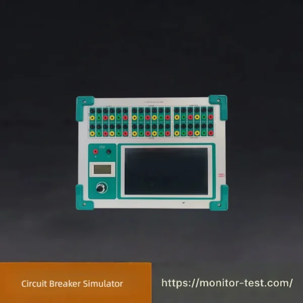
HF-WC-615 Circuit Breaker Simulator
This professional Circuit Breaker Simulator is specially designed for relay protection commissioning in substations and power plants. It can fully simulate closing and opening actions of high-voltage breakers with adjustable time parameters, replacing physical circuit breakers to complete secondary loop tests safely and efficiently.
Send your requirements, we will quote for you within 12 hours
The HF-WC-615 Circuit Breaker Simulator is mainly applied to the overall group testing of relay protection devices. It serves as a substitute for actual circuit breakers during linkage commissioning tests for relay protection and automatic control systems across various test projects.
It delivers accurate and reliable operations with unlimited actuation cycles. The equipment greatly improves the accuracy and integrity of tests, reduces the switching times of physical high-voltage breakers, and extends their service life.
This simulator can be used together with relay protection testers or operated independently. Especially when newly built power plants and substations have unfinished high-voltage breaker commissioning or no DC power supply available, it enables unaffected relay protection testing, shortens debugging periods and boosts work efficiency. It brings remarkably higher productivity for electrical manufacturers and research institutes, and can be adapted for other customized application scenarios.
It delivers accurate and reliable operations with unlimited actuation cycles. The equipment greatly improves the accuracy and integrity of tests, reduces the switching times of physical high-voltage breakers, and extends their service life.
This simulator can be used together with relay protection testers or operated independently. Especially when newly built power plants and substations have unfinished high-voltage breaker commissioning or no DC power supply available, it enables unaffected relay protection testing, shortens debugging periods and boosts work efficiency. It brings remarkably higher productivity for electrical manufacturers and research institutes, and can be adapted for other customized application scenarios.
Main Features
- Equipped with one group of isolated adjustable DC power supply, with a meter to display closing voltage value
- Comes with three groups of closing & tripping coils simultaneously
- Built-in manual closing and tripping functions
- Multi-stage adjustable resistance values for closing/tripping coils
- Multiple optional time ranges for closing and tripping output
- Multiple pairs of idle contacts for breaker position signal output
- Multiple pairs of idle contacts for closing & tripping pulse output
- Adopts single-chip microcomputer control system, supporting intelligent upgrading to meet diverse testing demands
- High-performance hardware platform: all main components comply with industrial standards, and core parts adopt military-grade components to guarantee superior product quality
Main Technical Parameters
- Operating Power Supply: AC220V±10%, 50Hz; Operating Current: < 0.5A
- Position Output Contacts: 6 pairs of mutually independent breaker position contacts, divided into two groups matching breaker trip coils; additional 3 pairs for closing pulses and 3 pairs for tripping pulses
- Operating Voltage for Closing & Tripping: Adjustable DC 40V ~ 250V
- Closing / Tripping Time: Freely settable from 10ms to 1000ms, tolerance ≤ ±5ms
- Closing / Tripping Current (Coil Resistance): Infinite Ω, 880Ω, 440Ω, 220Ω, 110Ω, 44Ω
- Manual Closing & Tripping: Operated via touchscreen buttons for manual close/trip; no current flows through coils during manual operation
- Contact Capacity: DC220V/0.5A, AC220V/5A
- Closing & Tripping Pulse Output: 3 groups of 500ms switching quantity contacts
- Standard Closing/Tripping Current: 0A, 0.25A, 0.5A, 1A, 2A, 5A
- When the trip/closing pulse voltage is 110V, the corresponding currents are: 0A, 0.125A, 0.25A, 0.5A, 1A, 2.5A
Packing List
| Serial No. | Item Name & Description | Quantity | Unit |
|---|---|---|---|
| 1 | Main Control Host (HZMN-III Circuit Breaker Simulator with touch screen) | 1 | Set |
| 2 | Output Signal Connection Cables (for trip & close contacts) | 1 | Set |
| 3 | Power Input Cable AC220V | 1 | Piece |
| 4 | Jumper Wires & Terminal Test Leads | 1 | Set |
| 5 | English & Chinese User Operation Manual | 1 | Copy |
| 6 | Factory Calibration Certificate | 1 | Copy |
| 7 | Factory Inspection Test Report (FAT Report) | 1 | Copy |
| 8 | Spare Fuses & Small Consumable Parts | 1 | Set |
| 9 | Portable Shockproof Aluminum Alloy Carrying Case | 1 | Set |
FAQ | Circuit Breaker Simulator
Q1: What is the main purpose of this circuit breaker simulator?
A1: It replaces real high-voltage circuit breakers to conduct overall linkage tests for relay protection devices. It cuts wear on actual breakers and improves the accuracy & efficiency of power system secondary circuit commissioning.
Q2: Can this simulator work alone, or does it have to match a relay protection tester?
A2: It supports two usage modes: independent operation, or matched use together with various relay protection test instruments for complete transmission tests.
Q3: Why is this device widely used for newly-built substations?
A3: For new stations without finished breaker debugging or available DC operating power, it can finish relay tests without external limitations and greatly shorten the whole debugging cycle.
Q4: How many groups of closing and tripping coils does the equipment have?
A4: It is equipped with 3 groups of closing & tripping coils to satisfy multi-loop protection system testing requirements.
Q5: Is the closing/tripping time adjustable? What is the adjustment range?
A5: Yes. The action time can be arbitrarily set between 10ms ~ 1000ms, with a time error no more than ±5ms.
Q6: Can we adjust the coil resistance and operating current?
A6: Multiple coil resistance gears (∞, 880Ω, 440Ω, 220Ω, 110Ω, 44Ω) are selectable, corresponding to different tripping/closing current levels to simulate various actual breakers.
Q7: What range does the DC operating voltage support?
A7: The closing and tripping DC voltage is continuously adjustable from 40V to 250V, compatible with common operating voltages of power system breakers.
Q8: What kinds of auxiliary contacts does the device provide?
A8: It has 6 pairs of breaker position contacts, plus 3 pairs of closing pulse contacts and 3 pairs of tripping pulse contacts, all isolated idle contacts for signal transmission.
Q9: Does it have manual closing and tripping functions?
A9: Yes. You can trigger manual open/close via touchscreen buttons; no current passes through coils under manual operation.
Q10: What power supply does the simulator need for operation?
A10: Standard input power is AC 220V±10%, 50Hz, and the total working current is less than 0.5A, energy-saving and safe for field use.
Q11: Can the device be upgraded with more functions later?
A11: It adopts single-chip microcomputer intelligent control hardware platform, which supports software upgrading to expand new testing functions as needed.
Q12: What packaging and documents will be delivered together with the machine?
A12: Packaged in a shockproof portable aluminum case. Delivered items include operation manual, factory inspection report, calibration certificate, connecting wires and spare fuses.
Q13: What is the service life advantage compared with using real breakers for testing?
A13: The simulator has unlimited operation times. Frequent testing will not cause mechanical fatigue, effectively extending the service life of expensive on-site high voltage circuit breakers.
Reviews
There are no reviews yet.