Leave your message

-
Leon Zhang sales consultant
-
Email: zxl635973785@gmail.com
-
Phone/WhatsApp/Wechat: +86 13655813266

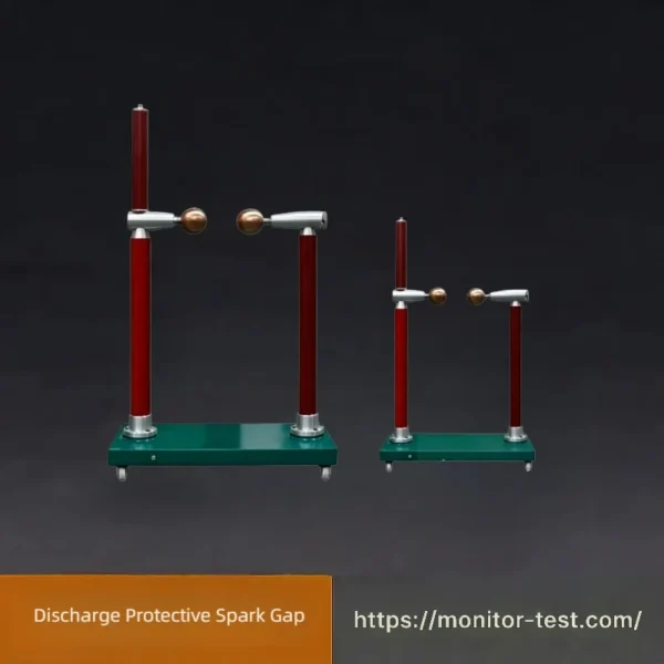
HF-ET-806 Discharge Protective Spark Gap
Protective Spark Gap provides reliable overvoltage protection for power‑grid equipment. It rapidly discharges lightning and switching surge energy, limiting over‑voltage amplitude to protect insulators and other key electrical components from damage.
Send your requirements, we will quote for you within 12 hours
Discharge Protective Spark Gap Overview
This discharge protective spark‑gap is a high‑voltage overvoltage protection device. It adopts adjustable ball‑gap structure to trigger breakdown under lightning or switching overvoltage, diverting surge current to ground. It effectively limits overvoltage level and protects power‑system insulators and electrical equipment from flashover and damage, widely used for high‑voltage test and power‑grid protection scenarios.
Technical Parameters
During test, connect the sphere‑gap discharger in parallel with the test object. The sphere‑gap itself is fitted with a protective resistor of 1 Ω per volt. Adjust the sphere gap to 60 % of test voltage (sphere gap distance can be checked from Table 1 & Table 2). Meanwhile, connect the test sample for measurement. When sphere gap discharges, take 3‑4 readings from the low‑voltage side voltmeter of test transformer. Repeat the procedure for 70 % and 80 % test‑voltage to obtain voltmeter readings. Plot the three‑point calibration curve (mostly a straight line). Extend the curve (mostly linear extrapolation) to target test‑voltage value and get the corresponding low‑side voltmeter reading. Set the sphere‑gap distance 10‑15 % higher than test‑voltage value, to provide over‑voltage discharge protection during withstand‑voltage test.
Table 1: Earthed‑sphere gap for AC voltage, negative lightning‑impulse voltage, long‑tail impulse and two‑polarity DC voltage (kV, peak value)
| Sphere‑gap Distance (cm) | Sphere Diameter 5 cm | Sphere Diameter 10 cm | Sphere Diameter 15 cm | Sphere Diameter 25 cm |
|---|---|---|---|---|
| 0.20 | ||||
| 0.25 | ||||
| 0.30 | ||||
| 0.40 | ||||
| 0.50 | 16.8 | |||
| 0.60 | 19.9 | |||
| 0.70 | 8.0 | 16.8 | 23.0 | |
| 0.80 | 9.6 | 19.9 | 26.0 | |
| 0.90 | 11.2 | 23.0 | 28.9 | 31.7 |
| 1.0 | 14.3 | 26.0 | 31.7 | 37.4 |
| 1.2 | 17.4 | 28.9 | 37.4 | 42.9 |
| 1.4 | 20.4 | 31.9 | 42.9 | 42.9 |
| 1.5 | 23.4 | 37.4 | 45.5 | 45.5 |
| 1.6 | 26.3 | 42.9 | 48.1 | 48.1 |
| 1.8 | 29.2 | 45.5 | 53.5 | 53.5 |
| 2.0 | 32.0 | 48.1 | 59.0 | 59.0 |
| 2.2 | 37.6 | 53.5 | 64.5 | 64.5 |
| 2.4 | 42.9 | 59.0 | 70.0 | 70.0 |
| 2.6 | 45.5 | 64.5 | 75.5 | 75.5 |
| 2.8 | 48.1 | 69.5 | 80.5 | 81.0 |
| 3.0 | 53.3 | 74.5 | 85.5 | 86.0 |
| 3.5 | 57.5 | 79.5 | 98.0 | 99.0 |
| 4.0 | 61.5 | 84.0 | 110 | 112 |
| 4.5 | 65.5 | 95.5 | 122 | 125 |
| 5.0 | (69.0) | 105 | 133 | 137 |
| 5.5 | (72.5) | 115 | 143 | 149 |
| 6.0 | (75.5) | 123 | 152 | 161 |
| 6.5 | (82.5) | (131) | 161 | 173 |
| 7.0 | (88.5) | (138) | 169 | 184 |
| 7.5 | (144) | 177 | 195 | |
| 8.0 | (150) | (185) | 206 | |
| 9.0 | (155) | (198) | 226 | |
| 10 | (209) | 244 | ||
| 11 | (219) | 261 | ||
| 12 | (229) | 275 |
Table 2: Earthed‑sphere gap for positive‑polarity lightning‑impulse voltage & long‑tail impulse voltage (kV, peak value)
| Sphere‑gap Distance (cm) | Sphere Diameter 5 cm | Sphere Diameter 10 cm | Sphere Diameter 15 cm | Sphere Diameter 25 cm |
|---|---|---|---|---|
| 0.30 | ||||
| 0.40 | ||||
| 0.50 | 16.8 | |||
| 0.60 | 19.9 | |||
| 0.70 | 23.0 | |||
| 0.80 | 16.8 | 26.0 | ||
| 0.90 | 11.2 | 19.9 | 28.9 | 31.7 |
| 1.0 | 14.3 | 23.0 | 31.7 | 31.7 |
| 1.2 | 17.4 | 26.0 | 37.4 | 37.4 |
| 1.4 | 20.4 | 28.9 | 42.9 | 42.9 |
| 1.5 | 23.4 | 31.7 | 45.5 | 45.5 |
| 1.6 | 26.3 | 37.4 | 48.1 | 48.1 |
| 1.8 | 29.2 | 42.9 | 53.5 | 53.5 |
| 2.0 | 32.0 | 45.5 | 59.0 | 59.0 |
| 2.2 | 37.8 | 48.1 | 64.5 | 64.5 |
| 2.4 | 43.3 | 53.5 | 70.0 | 70.0 |
| 2.6 | 46.2 | 59.0 | 75.5 | 75.5 |
| 2.8 | 49.0 | 64.5 | 80.5 | 80.5 |
| 3.0 | 54.5 | 70.0 | 85.5 | 85.5 |
| 3.5 | 59.5 | 75.5 | 98 | 99.0 |
| 4.0 | 64.5 | 80.5 | 111 | 112 |
| 4.5 | 69.0 | 85.5 | 124 | 125 |
| 5.0 | (73.0) | 97.5 | 136 | 138 |
| 5.5 | (77.0) | 109 | 147 | 151 |
| 6.0 | (81.0) | 120 | 158 | 163 |
| 6.5 | (90.0) | 130 | 168 | 175 |
| 7.0 | (97.5) | 139 | 178 | 187 |
| 7.5 | 148 | 187 | 199 | |
| 8.0 | 156 | 196 | 211 | |
| 9.0 | 163 | 212 | 233 | |
| 10 | 170 | 226 | 254 | |
| 11 | 238 | 273 | ||
| 12 | 249 | 291 |
Authority Identification
Manufactured strictly in accordance with international standards, national standards and industry specifications. Tested by national, provincial & municipal electric‑power research institutes, metrology centers and power‑sector authorities. Fully certified by ISO9001 international quality‑management‑system.
FAQ‑Discharge Protective Spark Gap
Q1: What is Discharge Protective Spark Gap used for?
A: It is an adjustable high‑voltage sphere‑gap device. Mainly used in high‑voltage withstand‑voltage tests, it provides over‑voltage discharge protection to prevent test samples from damage caused by unexpected over‑voltage.
Q2: What voltage types can this spark gap handle?
A: Suitable for AC voltage, positive/negative polarity lightning impulse, long‑tail impulse and bipolar DC voltage. Breakdown voltage depends on sphere diameter and sphere‑gap distance.
Q3: How to adjust its protective action voltage?
A: Refer to standard sphere‑gap breakdown voltage tables. Set the gap distance 10‑15 % higher than the target test voltage to realize over‑voltage triggering protection.
Q4: What is the function of the built‑in protective resistor?
A: Equipped with 1 Ω per‑volt protective resistor. It limits discharge current and protects the sphere electrodes and test transformer during spark‑gap breakdown.
Q5: How to perform voltage calibration before test?
A: Take readings at 60 %,70 %,80 % of nominal test voltage, plot calibration curve and extrapolate to get corresponding low‑voltage‑side reading for high‑voltage value.
Q6: What sphere diameters are available?
A: Common sphere diameters: 5 cm,10 cm,15 cm,25 cm. Different diameters correspond to different breakdown voltage ranges.
Q7: Spark gap discharges far below expected test voltage
A: Check for surface dirt, moisture or damage on sphere electrodes. Re‑check gap distance setting; ensure electrodes are well‑aligned and parallel.
Q8: No discharge occurs when over‑voltage appears
A: Confirm gap distance is not set excessively large. Inspect electrode surface for oxidation; verify protective resistor is intact without open‑circuit fault.
Q9: Why sphere‑gap breakdown data are in parentheses in tables?
A: Values in parentheses are reference data for limited‑use conditions, not for high‑precision measurement.
Q10: What are typical application scenarios?
A: Widely deployed in high‑voltage test laboratories, power‑equipment withstand‑voltage tests, insulation performance verification for transformers, insulators and other HV apparatus.
Reviews
There are no reviews yet.