Leave your message

-
Leon Zhang sales consultant
-
Email: zxl635973785@gmail.com
-
Phone/WhatsApp/Wechat: +86 13655813266

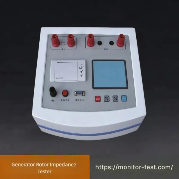
HF-ET-802 Generator Rotor Impedance Tester
Generator Rotor Impedance Tester is a dedicated test instrument for power industry. It precisely measures generator rotor impedance to identify inter-turn short circuits and winding aging faults, widely used in power plant routine inspection and equipment overhaul.
Send your requirements, we will quote for you within 12 hours
Product Overview
Generator Rotor Impedance Tester is a special testing instrument for power plants. It accurately measures the AC impedance, voltage and current of generator rotors to judge winding inter-turn short circuit, aging and hidden faults. Widely applied in generator routine inspection, overhaul and preventive maintenance of power generation equipment.
Technical Parameters
| Item | Specification | Accuracy Class |
|---|---|---|
| AC Impedance | 0 ~ 999.9Ω | 0.5 |
| AC Voltage | 0 ~ 600V | 0.5 |
| AC Current | 0 ~ 120A | 0.5 |
| Active Power | 0 ~ 72kW | 1.0 |
| Frequency | 45 ~ 75Hz | 0.2 |
| Working Power Supply | AC 220V±10%, 50Hz | ‑ |
| Dimensions | 415×225×200mm | ‑ |
| Weight | 5kg | ‑ |
Product Features
- Measure rotor AC impedance and characteristic curves of synchronous generators and asynchronous motor windings under static condition.
- Equipped with rotary mouse for convenient operation.
- Support two measurement modes: fast automatic measurement and manual selective measurement.
- Large‑screen Chinese menu interface, real‑time display of test data and curves.
- Data storage, built‑in mini‑printer for instant printing of test data & characteristic curves.
- Automatically adjust protection threshold according to test parameters to guarantee equipment safety.
- Capable of no‑load & short‑circuit test for single‑phase transformers, as well as volt‑ampere characteristic test for voltage/current transformers and arc‑suppression coils.
Operation Procedure of Generator Rotor Impedance Tester
- Confirm the generator rotor is fully power-off and safely grounded to eliminate residual electricity.
- Connect the tester’s measuring clamps to the rotor winding terminals correctly according to wiring diagram.
- Switch on the tester, set corresponding test parameters including voltage range and frequency.
- Choose automatic quick test or manual selective test mode and start measurement.
- Observe real-time impedance, voltage, current data and characteristic curves on screen.
- Save test records or print reports via the built-in printer after measurement finishes.
- Cut off output power of the tester, remove test wires and complete the whole test.
FAQ for Generator Rotor Impedance Tester
Q1: What is the main purpose of the generator rotor impedance tester?
A: It measures the AC impedance, DC resistance and inductance of generator rotor windings. It identifies rotor inter‑turn short‑circuit faults, evaluates winding insulation status, and supports factory acceptance, overhaul inspection and regular preventive maintenance for turbo‑generators and hydro‑generators.
Q2: What types of generators are applicable for this tester?
A: It fits most turbo‑generators, hydro‑generators and synchronous motor rotors. Applicable unit capacity covers small‑medium to large‑scale generators. Please confirm rotor rated voltage, current and winding parameters before field testing.
Q3: What pre‑work shall be completed before rotor impedance test?
- The generator shall be fully shut‑down, locked‑out and tagged; rotor shall be fully de‑energized and discharged.
- Disconnect slip‑ring external excitation cables; remove any parallel‑connected devices.
- Clean carbon brushes and slip‑ring surfaces to eliminate poor‑contact interference.
- Confirm rotor temperature is stable; record ambient temperature and rotor body temperature for data correction.
Q4: Why test AC impedance instead of only measuring DC resistance?
A: DC resistance mainly reflects direct winding conductor breakage or serious contact issues. Rotor inter‑turn short‑circuits with few shorted turns barely change DC resistance, but will cause obvious drop of AC impedance and inductance under AC excitation. AC impedance test is sensitive to minor inter‑turn short‑circuit defects.
Q5: How to judge whether rotor has inter‑turn short‑circuit fault via test data?
A: Compare measured impedance / inductance values with:
- Factory original test data
- Historical overhaul test records
- Homologous unit reference data
A remarkable drop of AC impedance (typically ≥5‑10%) under identical test frequency & temperature indicates high risk of rotor inter‑turn short‑circuit. Temperature correction shall be applied before comparison.
Q6: What factors will affect test accuracy?
- Poor contact on slip‑rings or test clips
- Residual magnetism on rotor core
- Rotor temperature deviation (winding resistance varies with temperature)
- Near‑by strong electromagnetic interference
- Improper test wiring or loose terminals
Q7: Can the test be performed with rotor rotating?
A: Standard rotor impedance test is performed under static rotor status. Rotating‑state test requires additional professional auxiliary equipment and safety measures; it is not recommended for conventional field maintenance.
Reviews
There are no reviews yet.