Leave your message

-
Leon Zhang sales consultant
-
Email: zxl635973785@gmail.com
-
Phone/WhatsApp/Wechat: +86 13655813266

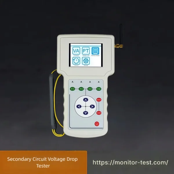
HF-MT-501 Secondary Circuit Voltage Drop Tester
The Secondary Circuit Voltage Drop Tester accurately detects voltage attenuation of current and voltage transformer secondary circuits. It judges circuit connection faults, ensures metering precision and safe operation of power measurement systems.
Send your requirements, we will quote for you within 12 hours
Model HF-MT-501 Wireless Secondary Circuit Voltage Drop Tester is also named secondary voltage drop on-site tester and transformer secondary voltage drop field tester. The device consists of two handheld measuring terminals, which can synchronously measure six channels of voltage amplitude and phase wirelessly, and can be independently used as a three-phase volt-ampere phase meter. Equipped with keypad operation, automatic range switching, large-capacity data storage and vector diagram display functions, it is ideal for on-site work including energy metering inspection, power inspection, substation maintenance, differential testing and startup tests for relay protection. It can also serve as wiring judgment training equipment and teaching instruments for power engineering colleges, and is applicable to large power-consuming enterprises in chemical industry, metallurgy, mining, railway and other sectors.
Product Features
- Distributed wireless synchronous measurement of volt-ampere phase electrical parameters; synchronous detection of six-channel voltage amplitude and phase, single-phase or three-phase secondary voltage drop measurement, with automatic ratio error and phase error calculation.
- Operates independently as a three-phase volt-ampere phase meter.
- No GPS module required, eliminating prolonged satellite searching caused by bad weather or high-rise shielding.
- No temporary cables needed between the watt-hour meter and PT terminal, preventing PT secondary short-circuit faults resulting from cable insulation defects or improper operation.
- Adopts wireless communication to avoid interference to secondary measurement loops caused by carrier communication, which may compromise energy metering accuracy.
- Supports both single-phase and three-phase measurement modes.
- Optional wireless repeater available to resolve wireless communication failure in basements and heavily shielded indoor environments.
- Minimum measurable current amplitude and phase reaches 1mA, perfectly suited for main transformer load tests in substations and current measurement for newly built substations or low-load substations.
- Automatic measurement range switching function.
- Fully isolated voltage and current sampling circuits.
- Firmware upgrade via SD card; measurement data can be exported to an SD card.
- Equipped with a 3.5-inch color LCD display.
- Built-in high-capacity lithium battery: continuous working time reaches 6 hours with LCD backlight on; longer standby time is available by enabling the backlight auto-off function.
- Wide operating temperature range: -20℃ to 50℃.
Technical Specifications
| Item | Parameter |
|---|---|
| Model | HF-MT-501 |
| Test Application | CT/PT secondary voltage drop measurement |
| Operating Power Supply | AC 185V~250V |
| Frequency | 50/60Hz |
| Input Power | 40VA |
| Connector | Standard DC plug |
| Ratio Error Measuring Range Measurement Accuracy Resolution |
0.001~99.9% X=±(1%×reading+1%×Y±0.02%) 0.001% |
| Phase Error Measuring Range Measurement Accuracy Resolution |
0.01~999.9 angular minutes Y=±(1%×X+1%×Y±0.5 angular minutes) 0.01 angular minutes |
| Voltage Measuring Range Measurement Accuracy Resolution |
5~600V 0.5%×reading±5 digits 0.1V |
| Current Measuring Range Measurement Accuracy Resolution |
0.001~6A (expandable) 0.5%×reading±5 digits 0.0001A |
| Active Power Measuring Range Measurement Accuracy Resolution |
0.005~3600W 0.5%×reading (PF=1) 0.1W |
| Reactive Power Measuring Range Measurement Accuracy Resolution |
0.005~3600Var 0.5%×reading (PF=0) 0.1Var |
| Frequency Measuring Range Measurement Accuracy Resolution |
45~65Hz ±0.02Hz 0.01Hz |
| Phase Angle Measuring Range Measurement Accuracy Resolution |
0~360° ±0.1° 0.1° |
| Ambient Conditions Operating Temperature Storage Temperature Humidity |
-20℃~+50℃ -20℃~+50℃ 5%~95% RH, non-condensing |
| Physical Dimensions Handheld Terminal (2 sets) Outer Packaging Case (2 sets) |
135×240×55mm 390×290×105mm |
| Weight Single Handheld Terminal (2 sets, excluding accessories) Total Weight (2 sets, with accessories) |
1kg 2.5kg |
FAQ – Secondary Circuit Voltage Drop Tester
Q1: What is a Secondary Circuit Voltage Drop Tester?
A: A live test device for PT secondary circuit, measuring voltage drop, secondary load, ratio & phase error and total metering error. It identifies wiring resistance-induced metering deviation to support circuit overhaul, loss analysis and fault diagnosis.
Q2: Typical application scenarios
A: Periodic substation PT loop inspection, new metering cabinet acceptance, abnormal power consumption troubleshooting, poor contact/cable aging inspection, PT load capacity verification.
Q3: Permissible voltage drop threshold (per DL/T 448)
A: Class I metering: ≤0.2% rated secondary voltage; Class II–IV: ≤0.5%. Excess drop leads to power revenue loss.
Q4: Supported wiring modes
A: 3P3L, 3P4L and single-phase PT circuits; wired and wireless synchronous master-slave versions available.
Q5: Live circuit testing allowed?
A: Yes for energized PT secondary circuits. Mandatory safety rules: use insulated tools, never short PT secondary terminals (will damage voltage transformer).
Q6: Preheating requirement
A: Warm up for 5 mins to stabilize internal circuit and minimize temperature drift error for millivolt-level voltage drop measurement.
Q7: Test cable requirements
A: Use shielded dedicated test cables. Check insulation with a 500V megohmmeter before use. Isolate spare cores to prevent shorting.
Q8: Measuring point layout
A: Master unit connects to PT secondary outlet (reference voltage); slave unit connects to energy meter inlet to calculate loop voltage difference.
Q9: No power-on display
A: Recharge battery or connect external power; check power switch and cable. Do not disassemble the device; contact after-sales service for repair.
Q10: Unstable fluctuating readings
A: Tighten oxidized test clips/terminals; keep test cables away from high-current busbars for anti-interference; test under stable grid load; re-pair wireless master-slave units.
Reviews
There are no reviews yet.