Leave your message

-
Leon Zhang sales consultant
-
Email: zxl635973785@gmail.com
-
Phone/WhatsApp/Wechat: +86 13655813266

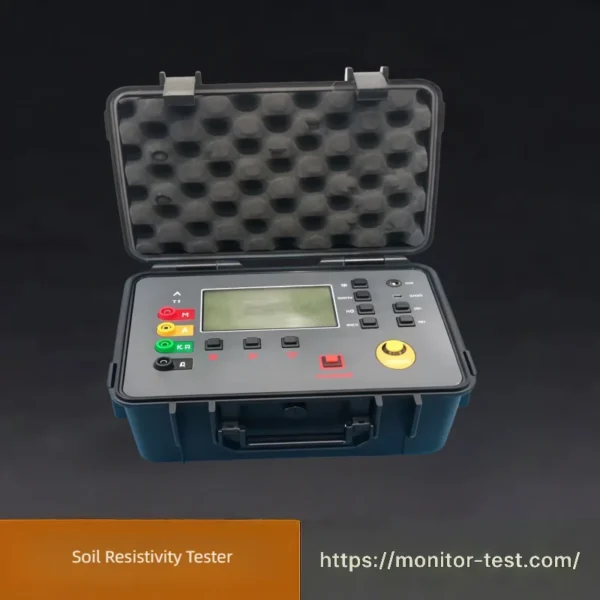
HF-GT-218 Soil Resistivity Tester
Soil Resistivity Tester adopts the classic Wenner four-electrode method to accurately measure soil resistivity and earth resistance on site. Equipped with strong anti-interference performance and digital display, it provides reliable data for grounding system design, lightning protection engineering and power infrastructure construction.
Send your requirements, we will quote for you within 12 hours
Overview
Soil Resistivity Tester is a professional field measuring instrument mainly applied to test soil resistivity, grounding resistance and ground stray voltage. It applies microprocessor digital technology and the standard four-pole Wenner measurement principle, effectively eliminating the interference of lead wire resistance and earth surface stray current to guarantee high test precision.
It supports 2/3/4-wire multiple testing modes, with built-in data storage function. Featuring compact portable structure, dustproof and waterproof casing, excellent anti-interference capability, it is widely adopted in power substations, communication stations, oil fields, construction lightning protection projects, meteorological facilities and industrial electrical grounding acceptance inspection. Accurate soil resistivity readings are essential to design qualified grounding grids, prevent electric shock hazards and ensure safe operation of all electrical equipment.
Applications of Soil Resistivity Tester
- Design and construction of power station, substation grounding grids, calculating proper grounding electrode layout according to soil resistivity data
- Lightning protection engineering inspection for buildings, communication base stations, oil depots and meteorological facilities
- Grounding resistance testing for industrial factories, chemical plants, petroleum and mining field electrical systems
- Geological prospecting, geophysical survey and underground pipeline laying preliminary site investigation
- Acceptance testing and regular maintenance of earthing systems to prevent electric leakage and lightning hazards
- Railway, highway traffic engineering grounding safety detection and civil construction electrical safety assessment
Technical Parameters of Soil Resistivity Tester
| Parameter Item | Specification |
|---|---|
| Measurement Modes | 2-wire, 3-wire, 4-wire measurement (Wenner four-electrode method for soil resistivity testing) |
| Measuring Range – Ground Resistance | 0.01Ω ~ 20kΩ |
| Measuring Range – Soil Resistivity | 0.01Ω·m ~ 20000Ω·m |
| Measuring Range – AC Stray Voltage | 0 ~ 40V |
| Measurement Accuracy – Ground Resistance | ±(2% reading + 0.05Ω) |
| Measurement Accuracy – Soil Resistivity | ±3% |
| Measurement Accuracy – Stray Voltage | ±1% |
| Test Current | Adjustable low-frequency AC test current, avoids soil polarization errors |
| Display | Large LCD digital screen, clear numerical display |
| Data Function | Built-in storage for 200 groups of test data; data can be viewed and exported |
| Anti-interference Design | Filters power frequency interference, adapts to complex field construction environments |
| Operating Conditions – Temperature | -10℃ ~ +50℃ |
| Operating Conditions – Humidity | ≤85%RH, no condensation |
| Power Supply | Built-in rechargeable lithium battery / AA dry batteries |
| Overall Size & Weight | Portable handheld design, lightweight, easy to carry for outdoor field surveys |
Packing List of Soil Resistivity Tester
|
No.
|
Item Name
|
Quantity
|
Remark
|
|---|---|---|---|
|
1
|
Soil Resistivity Tester Host
|
1 Set
|
Main unit
|
|
2
|
Test Electrodes (4 pcs)
|
4 Pcs
|
For 4-wire measurement
|
|
3
|
Test Connection Wires
|
4 Pcs
|
Red, yellow, green, black
|
|
4
|
Rechargeable Lithium Battery
|
1 Pc
|
Built-in type
|
|
5
|
Charging Adapter
|
1 Pc
|
For battery charging
|
|
6
|
User Manual
|
1 Copy
|
English version
|
|
7
|
Calibration Certificate
|
1 Copy
|
Optional
|
|
8
|
Portable Carry Case
|
1 Pc
|
For storage and carrying
|
FAQ for Soil Resistivity Tester
Q1: What is a Soil Resistivity Tester used for?
A1: It measures soil volume resistivity (ρ) via 4-pole Wenner method mainly. Test data is the core basis for designing grounding grids for substations, power plants, solar/wind farms, buildings and lightning protection systems, to calculate grounding resistance, select grounding electrodes and backfill materials.
Q2: What is the difference between soil resistivity tester and ordinary earth resistance tester?
A2: Soil resistivity tester adopts 4-terminal measurement exclusively for bulk soil resistivity. Common earth testers mostly measure finished grounding electrode resistance. Four-pole structure eliminates probe contact resistance interference for higher accuracy in layered soil detection.
Q3: Which testing method is adopted by your device?
A3: Standard Wenner 4-point method (most widely used per IEEE 81). Schlumberger array is also supported for deep soil layer exploration by adjusting probe spacing flexibly.
Q4: How to set probe spacing correctly? What does spacing determine?
A4: Four probes are arranged in a straight line with equal interval (a). The effective detection depth roughly equals interval a. Larger spacing = deeper soil layer measured. Multiple groups of spacing tests are required to judge layered soil structure.
Q5: How deep should I drive the metal probes into soil?
A5: Insert depth ≤ 1/20 of probe interval a. Too deep will distort horizontal layout and cause large measurement errors. Hard ground can pour a little water around probes to improve contact.
Q6: Why are readings unstable, flickering or jumping constantly?
A6: Main causes:
- Poor contact between probes and soil, loose wiring terminals, cracked test leads;
- Strong electromagnetic interference near high-voltage overhead lines, underground power cables;
- Buried metal pipes, steel bars, grounding conductors under test area;
- Low battery voltage of the host.Solutions: Re-plug wires, reinsert probes, stay away from electrified facilities, replace fully charged batteries.
Q7: Why do I get extremely low or false zero resistivity values?
A7: Conductive metal objects buried underground form shortcut loops, bypassing soil resistance. Move the test area at least 10m away from metal pipelines, steel structures and existing grounding networks to retest.
Q8: Negative resistivity values appear on display, is the instrument broken?
A8: Rarely device failure. Triggers: severely high contact resistance of electrodes, damaged cables, reversed wiring sequence, insufficient battery power. Check wire connection, polish rusty probes and recharge battery first before after-sales application.
Q9: What factors affect soil resistivity measurement results most?
A9: 1. Soil moisture: wet soil has much lower resistivity than dry soil;
2. Soil composition: clay < loam < sand < rock;
3. Temperature: low temperature increases resistivity obviously;
4. Seasonal variation: rainy season vs dry season data differs greatly.
Grounding design shall adopt dry season maximum resistivity as standard value.
2. Soil composition: clay < loam < sand < rock;
3. Temperature: low temperature increases resistivity obviously;
4. Seasonal variation: rainy season vs dry season data differs greatly.
Grounding design shall adopt dry season maximum resistivity as standard value.
Q10: Can I test on rocky, gravel or hardened ground?
A10: Yes. Drill small holes to place probes, fill holes with conductive clay or salt water to reduce contact resistance. Multiple repeated measurements are needed to get average valid data.

Reviews
There are no reviews yet.