Leave your message

-
Leon Zhang sales consultant
-
Email: zxl635973785@gmail.com
-
Phone/WhatsApp/Wechat: +86 13655813266

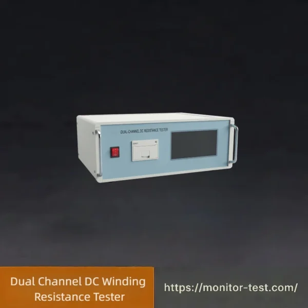
HF-TC-607 Dual Channel DC Winding Resistance Tester
This Dual Channel DC Winding Resistance Tester is tailor-made for temperature rise tests of large three-core five-limb transformers. It features rapid charging, dual synchronous measurement, real-time sampling and print output, with multiple current gears and high precision for transformer factory heat-run inspection.
Send your requirements, we will quote for you within 12 hours
This instrument complies with DL/T 845.3-2019 General Specifications for Resistance Measuring Devices — Part 3: DC Resistance Testers.
DC resistance testing is a mandatory procedure for semi-finished and finished factory inspection, site installation & handover tests, and routine preventive maintenance of transformers. It effectively detects manufacturing defects including improper coil material selection, defective welding, loose connections, strand breakage and wire fractures, as well as hidden faults generated during long-term operation.
To fulfill demands for fast transformer DC resistance measurement, this tester adopts innovative power supply technology with compact size, light weight and large output current. Controlled by single-chip microcomputer, it automatically completes self-check, data processing and display. It also features automatic discharge with clear discharge indication. With high measuring precision and user-friendly operation, it realizes ultra-fast DC resistance testing for transformers.
The HF-TC-607 Dual Channel DC Resistance Tester is purpose-built for temperature rise tests of large three-phase five-limb transformers. Its rapid charging and high-speed measurement fully satisfy time constraints of heat run tests. Dual-channel simultaneous measurement, real-time sampling and printable test reports eliminate difficulties in transformer temperature rise experiments.
Product Features
- High output current and high output voltage.
- Dual-channel measurement to capture two resistance values simultaneously.
- Unique proprietary protection circuit ensures outstanding reliability.
- Horizontal cabinet design for convenient operation inside transformer manufacturing workshops.
- Audible discharge alarm with clear discharge indication to avoid operational errors.
Product Parameters
- HV Side Output Current: <15mA, 40mA, 200mA, 1A, 5A, 10A
- LV Side Output Current: 2A, 5A, 10A, 20A
- Measuring Ranges
High Voltage Side
- 10A: 0.5mΩ ~ 0.8Ω
- 5A: 1mΩ ~ 2Ω
- 1A: 5mΩ ~ 10Ω
- 200mA: 100mΩ ~ 50Ω
- 40mA: 1Ω ~ 250Ω
- <15mA: 10Ω ~ 20kΩ
Low Voltage Side
- 20A: 100μΩ ~ 500mΩ
- 10A: 200μΩ ~ 1Ω
- 5A: 1mΩ ~ 1.6Ω
- 2A: 5mΩ ~ 4Ω
- Accuracy: ±(0.2% of reading + 2 digits)
- Resolution: 0.1μΩ
- Operating Temperature: 0℃ ~ 40℃
- Ambient Humidity: ≤90%RH, non-condensing
- Operating Power Supply: AC220V±10%, 50Hz±1Hz
- Overall Dimensions: 441mm × 450mm × 177mm
- Net Weight: 17.6KG
- Standard Test Lead Length: 10 meters; customized lengths available on request
Configuration List
| No. | Item Name | Qty | Unit |
|---|---|---|---|
| 1 | Main Tester Unit | 1 | Set |
| 2 | Test Lead Kit | 1 | Set |
| 3 | Power Cord | 1 | Piece |
| 4 | Operation Manual | 1 | Copy |
| 5 | Product Certificate | 1 | Piece |
| 6 | Fuse Tube | 2 | Pieces |
| 7 | Thermal Printing Paper Roll | 1 | Roll |
| 8 | Packing List | 1 | Copy |
| 9 | Ground Wire | 1 | Piece |
| 10 | Serial Communication Cable | 1 | Piece |
| 11 | Test Sample | 1 | Piece |
After-Sales Service Commitment
- We strictly supply qualified products fully compliant with design standards as specified in the signed contract.
- Rigorous inspection and quality control are implemented for all incoming raw materials, electronic components and auxiliary parts.
- All equipment undergoes complete processing and full testing before delivery, with zero defective units shipped from factory.
- If missing parts or damaged components are found after unpacking, we will supply free replacements promptly.
- Response Mechanism: We will reply immediately upon receiving quality feedback; our service engineers will arrive on-site within 24 hours. Service support will not stop until customers are fully satisfied with the solution.
- Warranty Policy: One-year full warranty for manufacturing defects under normal operation, three-year extended repair service, and lifelong technical maintenance support.
Applications of Dual Channel DC Winding Resistance Tester
This dual channel tester is specially developed for temperature rise tests of large three-core five-limb transformers, realizing two groups of windings measured simultaneously. It also performs routine DC resistance tests for distribution transformers, CT and reactors, identifying broken strands, loose connections and welding faults during factory inspection and substation handover tests.
Our Advantages
Our Dual Channel DC Winding Resistance Tester is specially optimized for temperature rise tests of large three-core five-limb transformers, overcoming the inefficiency of traditional single-channel testing. Featuring a high-power dedicated power supply, it delivers large output current and stable high voltage with fast magnetization and rapid measurement, fully meeting the strict time requirements of transformer heat-run tests.
It supports true dual-channel synchronous measurement to acquire two sets of winding resistance data in real time, greatly boosting testing efficiency while ensuring accurate and consistent test results. Built with a full independent protection circuit, the tester effectively withstands back EMF impact from inductive loads, preventing damage and guaranteeing stable long-term operation.
Adopting a practical horizontal structure, it is highly adaptable to continuous workshop operation in transformer factories. The built-in audible discharge alarm avoids operational errors and ensures testing safety. It also supports customized long test leads and integrated print output, enabling convenient on-site data recording and report generation.
FAQ
Q1: What is a dual channel DC winding resistance tester used for?
A1: A professional tester for DC resistance measurement of transformer, motor and generator windings. Its core dual-channel synchronous measurement feature improves testing efficiency significantly, supports three-phase winding resistance testing and unbalance rate calculation, and is widely used in power maintenance, electrical manufacturing and project acceptance.
Q2: What is the working principle of the device?
A2: It works on high-precision constant current source and Ohm’s law. The instrument outputs stable DC current to the tested winding, samples voltage drop via high-precision circuits, and calculates resistance value accurately. Dual-channel independent sampling guarantees synchronous and consistent dual-group test data.
Q3: What resistance range is the device applicable to?
A3: It covers micro-ohm to kilo-ohm range, suitable for low-resistance large power transformer windings and high-resistance small motor windings. The device automatically matches constant current gears to ensure testing accuracy and stability.
Q4: What are the advantages of dual-channel measurement over single-channel?
A4: ① Higher efficiency: Tests two windings simultaneously, eliminating repeated wiring and long charging waiting of single-channel devices; ② Better consistency: Synchronous current excitation and sampling avoid time difference and temperature drift errors; ③ Intelligent calculation: Automatically computes three-phase resistance unbalance rate to save manual work.
Q5: How to switch and view CH1 and CH2 channel data?
A5: Press the [Channel] key to switch CH1 and CH2 data display. The screen shows real-time resistance values of two channels separately. All data supports synchronous storage, one-key comparison and export.
Q6: Can I use single channel independently if only one winding needs testing?
A6: Yes. It supports both dual-channel synchronous test and single-channel independent test. Only connect the target channel wiring for single-winding testing; the instrument auto-identifies valid data without test result deviation.
Q7: Why is the measured data unstable and fluctuating greatly?
A7: ① Poor contact: Polish oxidized terminals and fasten test clamps tightly; ② Electromagnetic interference: Stay away from high-voltage and frequency-conversion equipment, enable anti-interference mode; ③ Unstable charging: Wait for current and voltage stabilization before recording data.
Q8: What to do if the three-phase winding resistance unbalance rate exceeds the standard?
A8: First check correct wiring and firm connection to exclude external errors. Standard-over unbalance rate indicates potential winding faults such as turn-to-turn short circuit, poor welding or loose turns, requiring further equipment inspection.
Q9: Why does the instrument prompt “Test line not connected”?
A9: This prompt means open circuit or poor loop connection. Check firm connection of current and voltage lines and good contact of test clamps. Eliminate virtual connection, press [Reset] and restart the test.
Q10: Why is the test value inaccurate with large error?
A10: ① Check damaged or high-resistance test lines; ② Match correct test gear (out-of-range resistance causes deviation); ③ Calibrate temperature impact by testing in stable environment and converting to standard temperature; ④ Conduct regular instrument calibration.
Reviews
There are no reviews yet.