Leave your message

-
Leon Zhang sales consultant
-
Email: zxl635973785@gmail.com
-
Phone/WhatsApp/Wechat: +86 13655813266

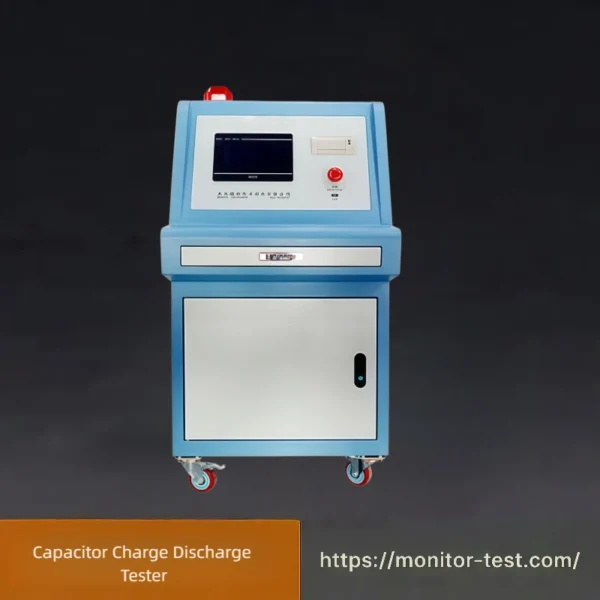
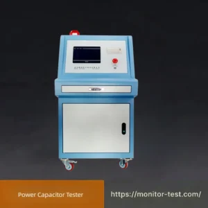
HF-PC-202 Capacitor Charge Discharge Tester
This capacitor charge discharge tester complies with GB/T 14472-2005 standard. It supports four synchronous test stations with adjustable DC voltage, built-in overvoltage and overcurrent protection to complete cyclic charge-discharge tests accurately for power capacitors.
Send your requirements, we will quote for you within 12 hours
This capacitor charge-discharge test bench is dedicated equipment for charging tests on safety capacitors, capable of measuring the dV/dt characteristics of capacitors with an oscilloscope. It adopts a constant voltage & constant current DC power supply to charge sample capacitors, while electronic switches are deployed for discharging control. A 7-inch true-color touchscreen is used for parameter display and operation control, and a PLC serves as the lower computer to realize automatic system control in strict accordance with test standard requirements.
Its charging power supply adopts a high-voltage DC power supply based on Zero-Voltage Switching full-bridge/half-bridge circuit topology combined with advanced PWM control technology. It features fast dynamic response of output voltage and current, as well as high precision of voltage and current output.
Product Features
● Ultra-fast output voltage response: Response time reaches millisecond level;
● Adjustable charging current: Built-in constant voltage and constant current functions;
● High display precision: Minimum resolution up to 0.1V;
● Ultra-low ripple factor: Less than 1% FS (Full Scale);
● Excellent stability: 1V display resolution with precision up to 0.2%;
● Automatic overvoltage and overcurrent protection function equipped;
● Compact size: Only 2U in height.
● Adjustable charging current: Built-in constant voltage and constant current functions;
● High display precision: Minimum resolution up to 0.1V;
● Ultra-low ripple factor: Less than 1% FS (Full Scale);
● Excellent stability: 1V display resolution with precision up to 0.2%;
● Automatic overvoltage and overcurrent protection function equipped;
● Compact size: Only 2U in height.
Compliant Standards
Clause 4.15 Charge and Discharge Test specified in GB/T 6346.14-2015 (identical to IEC 60384-14:2016)
Technical Specifications
| Parameter Item | Specification |
|---|---|
| Test Type | Capacitor charge-discharge test (dV/dt test) |
| Test Stations | 3 synchronous stations |
| DC Voltage Range | 0V ~ 1000V |
| Display Resolution | 1V |
| Display Accuracy | ±1% ± 2 digits |
| Maximum Test Capacitance | ≤1μF |
| Charging Resistance | 389Ω / 438Ω, external resistor configurable; support optional short-circuit |
| Discharging Resistance | 5Ω / 50Ω, external resistor configurable; support optional short-circuit |
| Charging Time Range | 0.1s ~ 999s |
| Discharging Time Range | 0.1s ~ 999s |
| Time Accuracy | ±1% |
| Maximum Test Cycles | 99999 times |
| Cycle Count Accuracy | ±1 count |
| Test Chamber | Integrated built-in chamber, equipped with safety door interlock protection |
| Optional Accessories | Oscilloscope + Voltage Probe |
| Input Power | AC220V±10%, 50Hz |
| Overall Cabinet Size | 650mm (Width) × 850mm (Depth) × 1650mm (Height) |
Capacitor Charge-Discharge Tester Operation Steps
1. Pre-Test Preparation
Check equipment power (AC220V±10%, 50Hz) and safety interlock function. Fully discharge the test capacitor before connection. Wear insulating gloves for high-voltage operation.
2. Sample Installation
Open the test chamber, install the capacitor correctly with positive and negative polarity. Close the safety door tightly to activate high-voltage enable.
3. Parameter Setting
Set test parameters on the control panel:
-
Test mode: Charge-discharge (dV/dt) test
-
DC voltage: 0V ~ 1000V
-
Charging resistance: 389Ω / 438Ω or external resistor
-
Discharging resistance: 5Ω / 50Ω or external resistor
-
Charging / discharging time: 0.1s ~ 999s
-
Test cycles: 1 ~ 99999
Connect oscilloscope and voltage probe if waveform recording is required.
4. Start Test
Confirm all parameters, then press START. The machine performs automatic cyclic charging and discharging. Three test stations work synchronously and record dV/dt voltage change data in real time.
5. Test Completion
The tester stops automatically after completing preset cycles. Save test data, cycle records and voltage waveforms.
6. Post-Test Operation
Press STOP to cut off high voltage. Keep the capacitor in discharge state to release residual voltage. Take out the sample, turn off the power and tidy up the test accessories.
7. Safety Instructions
-
Do not open the safety door during testing.
-
Strictly discharge residual voltage before wiring and disassembling.
-
Stop the test immediately if overvoltage or abnormal alarm occurs.
Capacitor Charge Discharge Tester FAQ
Q1: What is a Capacitor Charge Discharge Tester used for?
A: A professional device for testing capacitor electrical performance. It simulates real charge-discharge working conditions to test key parameters including capacitance, charge/discharge time, leakage current, ESR and residual voltage. It is widely used for R&D verification, quality inspection and aging test of electrolytic, ceramic, film capacitors and supercapacitors.
Q2: What types of capacitors can this tester test?
A: It supports mainstream capacitors: aluminum electrolytic, tantalum, ceramic, film capacitors and supercapacitors. It covers small chip capacitors to high-power industrial capacitors, suitable for civil, automotive, industrial and new energy scenarios.
Q3: What are the core test parameters of the instrument?
A: Core test parameters: charge/discharge time, steady-state voltage, residual voltage, charge/discharge current, leakage current, capacitance accuracy, ESR and cycle failure times. Advanced models support temperature rise and overvoltage protection tests.
Q4: Why does the tester show “test failure” immediately after starting the test?
A: Main causes and solutions: 1) Loose connection or open circuit: re-clamp terminals firmly. 2) Damaged capacitor (short/open circuit): replace the sample. 3) Overrated test voltage/current: reset parameters within capacitor nominal range. 4) Oxidized probe: clean probes with alcohol.
Q5: How to set the charging and discharging cycle test correctly?
A: 1) Confirm the capacitor’s rated voltage and current to avoid over-parameter damage. 2) Set charge/discharge time and cycle times (single manual / automatic cyclic test). 3) Select constant voltage charging / constant current discharging mode as required and start the test. Follow IEC/GB standards for batch testing.
Q6: Does the instrument need regular calibration? How often?
A: Regular calibration is required for accuracy. Standard cycle: 12 months for daily laboratory/factory use. 6 months for high-frequency use or harsh high-temperature/humidity environments. Emergency calibration is needed after transportation, impact or obvious data deviation.
Q7: Can I test capacitors with different specifications continuously?
A: Continuous testing is allowed, but reset voltage/current/time parameters when switching capacitor specs. Never test low-voltage small capacitors with high-voltage/high-current parameters to avoid breakdown or device damage. Cool down the tester after high-power capacitor tests before testing small samples.
Q8: Why are the tested capacitance values inconsistent with the nominal values?
A: Minor deviation from nominal value is normal (tolerance: ±5%/±10%/±20%). Main deviation causes: capacitor aging, ambient temperature change, mismatched test parameters and poor contact. Test at standard room temperature (25℃±2℃) and ensure firm connection for accurate data.
Q9: What is leakage current of capacitor? Is large leakage current unqualified?
A: Leakage current is the tiny internal dielectric current of a fully charged capacitor under constant voltage. Slight leakage is normal for electrolytic capacitors, while excessive leakage indicates aging or internal defects (unqualified). Film and ceramic capacitors have negligible leakage; any obvious leakage means abnormality.
Q10: Why does the residual voltage not drop to zero after discharge?
A: Slight residual voltage is a normal physical property of capacitors. Obvious residual voltage is mainly caused by insufficient discharge time or mismatched instrument discharge resistance. Residual voltage beyond industry standards indicates unqualified capacitor performance.
Reviews
There are no reviews yet.