Leave your message

-
Leon Zhang sales consultant
-
Email: zxl635973785@gmail.com
-
Phone/WhatsApp/Wechat: +86 13655813266

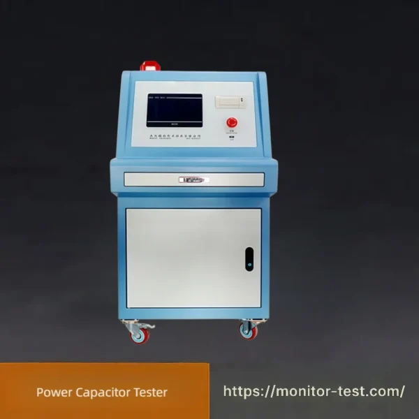
HF-PC-201 Power Capacitor Tester
This professional power capacitor tester performs standard charge and discharge tests for power capacitors. With four synchronous test channels and overvoltage & overcurrent protection, it precisely measures parameters to evaluate capacitor stability and service life.
Send your requirements, we will quote for you within 12 hours
This device applies DC power supply to perform charge and discharge tests on test capacitors. Designed and manufactured in compliance with Clause 4.15 of GB/T14472—2005 (Fixed capacitors for use in electronic equipment Part 14: Sectional specification – Fixed capacitors for electromagnetic interference suppression). It adopts Matsushita Electric timers and counters, features an output terminal for oscilloscope monitoring, built-in overcurrent & overvoltage protection circuits, and is equipped with a test box fitted with safety switches.
Main Technical Parameters
- Output DC voltage: 0 ~ 400V, continuously adjustable
- Digital display accuracy: ±3% ± 3 digits
- Test stations: 4 stations working synchronously
- 4 independent channels, charging current per channel: ≤ 1A
- Maximum capacitance of each tested capacitor: 1μF
- Maximum discharge rate: 100V/μs
- Tolerance: ±15%
- Timer range (charging & discharging duration): 0.1 ~ 999.9 seconds
- Timer accuracy: ±3%
- Counter range: 0 ~ 999999 times
- Counter accuracy: ±1 count
- Overcurrent & overvoltage protection: Protection thresholds can be continuously adjusted inside the device
- Reserved output port for oscilloscope monitoring
- Equipped with test box with safety switches
- Overall dimensions: approx. 600mm(L) × 600mm(D) × 1700mm(H)
- Operating power supply: AC220V±1%, 50Hz
Device Features
Identical to the product overview above: It is a DC-powered unit for capacitor charge-discharge testing, fully compliant with GB/T14472-2005 standards, equipped with Panasonic timing/counting modules, oscilloscope monitoring port, multi-layer safety protection circuits and safety-interlocked test box.
| Applicable Standard | Application Scope | Standard Accessories |
|---|---|---|
| GB/T 14472-2005 (IEC 60384-14:2001) | Fixed capacitors for EMI suppression, ceramic capacitors and related products | 1. 4-position test box ×1 2. Test lead set ×1 3. Power cord ×1 4. Operation manual ×1 5. Warranty card ×1 (1-year warranty) |
Operating Instructions for Power Capacitor Tester
Step 1: Pre-operation Preparation
- Place the device on a flat, well-ventilated indoor site; confirm ambient temperature and humidity meet the specified working conditions.
- Connect the power cord to AC220V mains power supply, check all circuits for no short circuit or loose wiring.
- Mount the 4-position test box, connect test leads between the tester and test box firmly.
Step 2: Parameter Setting
- Switch on the main power supply of the device, the display screen lights up to enter standby mode.
- Set target DC output voltage (0~400V adjustable), charging & discharging time (0.1~999.9s) via the control panel.
- Configure overcurrent and overvoltage protection thresholds according to tested capacitor specifications to avoid component damage.
- Set test cycle counting times as required.
Step 3: Install Test Samples & Start Test
- Open the safety switch cover of the test box, install capacitors to be tested on each of the 4 stations, close the safety cover tightly.
- Press the start button; four channels run synchronously to automatically complete charging and discharging cycles.
- Real-time voltage, time and cycle counts are displayed on the digital screen; you can connect an oscilloscope to the reserved port to observe waveform changes.
Step 4: Test Completion & Shutdown
- When the preset test cycles finish, the device stops running automatically and saves test data.
- Cut off the output voltage first, open the safety test box after complete capacitor discharge, then take down tested capacitors.
- Turn off the main power switch, unplug the power cord, tidy up test wires and accessories.
Safety Notes
- Never touch capacitor terminals during charging/discharging to prevent electric shock.
- Stop the test immediately once overvoltage/overcurrent alarm triggers.
- Do not test capacitors exceeding the maximum 1μF capacity limit.
FAQ for Power Capacitor Charge-Discharge Tester
Q1: Which standard does this capacitor tester comply with?
A1: It fully conforms to GB/T 14472-2005 (IEC 60384-14:2001), designed following Clause 4.15 for EMI suppression fixed capacitors.
Q2: How many capacitors can be tested at the same time?
A2: Equipped with 4 synchronous test channels. Four capacitors can undergo charge-discharge cycling tests simultaneously to improve testing efficiency.
Q3: What is the adjustable range of output DC voltage?
A3: The DC output voltage is continuously adjustable from 0V to 400V, which can meet the test requirements of most ceramic and EMI suppression capacitors.
Q4: What protection functions does the device have?
A4: It supports adjustable overcurrent and overvoltage protection thresholds. It will automatically cut off the circuit to protect both the device and test samples once abnormal conditions occur.
Q5: Can I observe the voltage waveform during testing?
A5: Yes. An exclusive output port is reserved for oscilloscope connection, allowing real-time monitoring of charge and discharge waveforms on screen.
Q6: What are the limits of timer and counter?
A6: Timer range: 0.1~999.9 seconds with ±3% accuracy; counter can record up to 999999 test cycles accurately.
Q7: What is the maximum capacitance available for testing?
A7: The maximum capacitance of a single tested capacitor shall not exceed 1μF.
Q8: What accessories are delivered together with the machine?
A8: 4-position test box, a set of test cables, power cord, user manual and warranty card with one-year free maintenance service.
Q9: What is the required working power supply?
A9: Rated input power is AC 220V ±1%, 50Hz, which fits common industrial workshop power supply conditions.
Q10: Why is the safety switch installed on the test box?
A10: For electric shock prevention. The test loop will be disconnected automatically once the box is opened during operation, ensuring operator personal safety.
Reviews
There are no reviews yet.